
D10.5 Intermediate Training Documentation
(M18) April 2007
Project number
IST-027635
Project acronym
Open_TC
Project title
Open Trusted Computing
Deliverable Type
Report
Reference number
IST-027635 /D10.5/V1.0 Final
Title
D10.5 Intermediate Training Documentation
WPs contributing
WP10
Due date
April 2007 (M18)
Actual submission date
June 14, 2007
Responsible Organisation
PORT
Authors
PORT (Bora Güngören, Burak Oğuz), RHUL
(Chris Mitchell, Stephane Lo Presti, Eimear
Gallery), IAIK (Peter Lipp, Thomas Winkler,
Martin Pirker), HP (Graeme Proudler), CUCL
(Steve Hand)
Abstract
This document includes a summary of each
partner's training work, divided in relevant
sections describing initiation of courses,
development of material, licensing issues,
and the material themselves, compared to
the learning objectives set in D10.4. Lecture
notes and supplementary material developed
by each partner is at the end of this
document.
Keywords
OpenTC, Training, Virtualization, Trusted
Computing, Strategy
Dissemination level
Public
Revision
V1.0 Final
Instrument
IP
Start date of the
project
1
st
November 2005
Thematic Priority
IST
Duration
42 months

Intermediate Training Documentation
1.0
If you need further information, please visit our website
www.opentc.net
or contact
the coordinator:
Technikon Forschungs-und Planungsgesellschaft mbH
Richard-Wagner-Strasse 7, 9500 Villach, AUSTRIA
Tel.+43 4242 23355 –0
Fax. +43 4242 23355 –77
Email
coordination@opentc.net
The information in this document is provided “as is”, and no guarantee
or warranty is given that the information is fit for any particular purpose.
The user thereof uses the information at its sole risk and liability.
Open_TC Deliverable 10.5
1/12

Intermediate Training Documentation
1.0
Table of Contents
1 Introduction .............................................................................................................. .3
2 Initiation of Courses...................................................................................................4
2.1 University Courses.................................................................................................4
2.1.1 RHUL.......................................................................................................... ........4
2.1.2 IAIK....................................................................................................................4
2.1.3 Other Partners...................................................................................................5
2.2 Professional Courses..............................................................................................5
2.2.1 PORT............................................................................................. .....................5
2.3 Other Training Activities.........................................................................................6
2.3.1 PORT............................................................................................. .....................6
2.3.2 TEC....................................................................................................................6
3 Training Materials Produced.......................................................................................8
3.1 Objectives Set Previously.......................................................................................8
3.2 Licensing of the Material........................................................................................8
3.3 Training Materials Submitted by Each Partner........................................................8
3.3.1 RHUL.......................................................................................................... ........8
3.3.2 IAIK..................................................................................................................10
3.3.3 PORT........................................................................................... .....................10
4 List of Abbreviations ...............................................................................................11
5 Submitted Training Material.....................................................................................12
Open_TC Deliverable 10.5
2/12

Intermediate Training Documentation
1.0
1
Introduction
The Open Trusted Computing project aims to create an open source trusted platform
for software developers worldwide to use. This platform will also be interest to
academic world to analyze, test and improve the state of the art in security and
trusted platforms. Therefore it is crucial that correct and unbiased information on both
trusted computing and the developments of Open TC project be disseminated well.
A significant part of this dissemination involves public training material that can be
accessed without any restrictions. It was previously decided that training material
produced in the Open TC project should be delivered timely and in parallel to the
project deliverables. This document with its large appendices is the initial and yet to
be completed output of many Open TC partners.
As stated in the previous deliverable D10.4 Training Concepts and Training Plans
(M12), Open TC training will cover mainly two aspects.
●
The first aspect will be to assist existing professional developers and in
particular FOSS developers. As Europe has a significant share in the open source
software developer pool, this objective will contribute towards high quality
European projects making use of both trusted computing and the open source
trusted platform produced by Open TC.
●
The second aspect will be assist European universities and research institutes in
organizing lectures and courses on the same subject. However, citing D10.4,
“Academic training deals with a rather different audience than that for
professional training. Moreover, the nature of teaching in an academic
environment is very different to the short-term focused training typically
available in a commercial environment. Therefore it needs to fulfill rather
different goals.”
The 6 month period between the delivery of D10.4 and the submission of D10.5 has
been a busy period for all partners involved. Three university and research partners
(RHUL, IAIK and TUB) have started delivering university lectures related to the Open
TC project. Two industrial partners (TEC and PORT) have started work on public
material addressing practitioners. In summary, Open TC partners have delivered a
significant amount of high quality material in a very short time while working on
research tasks at the same time.
This document includes a summary of each partner's work, divided in relevant
sections describing initiation of courses, development of material, licensing issues, and
the material themselves, compared to the learning objectives set in D10.4. Lecture
notes and supplementary material developed by each partner is at the end of this
document.
Open_TC Deliverable 10.5
3/12

Intermediate Training Documentation
1.0
2
Initiation of Courses
2.1 University Courses
Three Open TC partners have initiated university courses related to Open TC project.
In the time of writing of this document,
●
RHUL had almost completed the academic semester for their course and hence
has the most complete documentation set in this deliverable. RHUL's
documentation also constitutes the major part of D10.5.
●
IAIK semester started later, so they prepared more limited material covering
more basic subjects. However they will be adding more material as their course
advances.
●
TUB is currently delivering an undergraduate security course that touches
slightly to Open TC project. The students taking this course will most likely take
a follow-up course dedicated to trusted computing, again presented by TUB
next semester. So their material was not submitted to this document but will be
publicized as the more advanced course is delivered.
As a non-academic partner, PORT is still working with a number of Turkish universities
to deliver a security course devoted to trusted computing. As regulations dictate, as
soon as a draft set of lecture notes are completed, faculty boards will discuss the
approval of the course delivered by a person external to the faculty.
2.1.1 RHUL
Royal Holloway has been a leader in security related graduate studies through their
Msc in Information Security program. In the current semester, they have offered a
course entitled “Trusted Computing”, devoted to enable the student to understand and
describe the theory behind trusted computing and use this fundamental knowledge to
design systems making use of trusted computing in order to increase overall system
and user security.
The course is divided in eleven 3-hour lectures, and intends to attract 30 graduate
students each year. This amount to almost 3.000 person-hours of training delivered to
future specialists in the European Information security area, during the Open TC
project schedule only.
One additional point on the course is that RHUL has collaborated with HP and CUCL,
with one expert from each organization delivering lectures as well as Stephane Lo
Presti and Eimear Gallery from RHUL. Prof. Chris Mitchell has, naturally, co-ordinated
the course and material development efforts.
As their semester is almost complete, RHUL has already started updating material on
the first set of lectures. It can be expected that, in the following months, RHUL will also
have improved their instructional methodology and will assist other partners by
transferring their experience.
2.1.2 IAIK
IAIK has started their summer term class on trusted computing (with official name “AK
IT-Sicherheit 1”) in March 2007. The course is coordinated by Peter Lipp and lectures
are so far delivered by Martin Pirker and Thomas Winkler.
Open_TC Deliverable 10.5
4/12

Intermediate Training Documentation
1.0
The course will introduce the students to understand the capabilities of TC-enabled
hardware and software, enable them to use several TPM features including more
advanced subjects such as TPM migration, and also explain use of virtualization in
security domain. The IAIK course also involves actual programming assignments with
computers equipped with TPMs or vTPMs.
2.1.3 Other Partners
PORT and TUB have also submitted their intention to deliver a complete course in a
number of Turkish universities. However, it is required that at least draft lecture notes
be presented prior to approval. Further requirements exist, but these can be handled
rather easily. This has delayed the delivery of both courses.
●
PORT has opted to wait until a draft for most of the lectures appear. As PORT
courseware are more practice oriented, this is also connected to delivery of
some OpenTC API's and infrastructures. If delays are experiences, the initial
course will have to make use of other resources for practical sessions.
●
TUB has opted to deliver a more introductory course at undergraduate level this
semester. The students taking this course are very interested in trusted
computing, some have even applied to summer practice in security related
organizations. TUB will be delivering a follow-up course, dedicated to trusted
computing and it is expected that most of these students will take that course
as well.
2.2 Professional Courses
Professional courses are often delivered to institutions and companies with their
employees already working on several projects. It is therefore very important that the
time spent is used economically; and the attendants are not expected to spend much
time on researching. A typical professional course is 30-hours long and is delivered in
5 consecutive days. This requires that the methodology of instruction and the
techniques used be very different from those in university courses.
2.2.1 PORT
As PORT has experience in delivering customized professional courses to many
software firms in Turkey, the approach for the public professional course has been
different. The course has been planned to include 7 modules and some of these
modules can be omitted for the needs of the attendants. Previous deliverable D10.4,
specified more than two hundred learning objectives to describe this course.
PORT submits one of the first three modules of this course together with D10.5. Initial
plan was to have these parts ready by March/April 2007 for peer review, however the
plan was delayed due to problems in recruiting the foreseen instructional technologist
and an extended sick leave by PORT's OpenTC manager Bora Güngören. Some lower
level deliverables were also delivered late, therefore delaying some modules .
Observing these delays, PORT research team has instead experimented on the PET
Demonstrator Prototype and particularly gained much experience in Xen virtualization.
They have also delivered many presentations and had a number of articles at national
level on these subjects. This will also be useful for PET related material development.
Following recovery of Bora Güngören and submission of the lower level deliverables,
Open_TC Deliverable 10.5
5/12

Intermediate Training Documentation
1.0
PORT has started working on the professional courseware again. Additionally WP06
efforts of PORT have also matured so some part of the workforce could be redirected
towards WP10 as well. PORT has thus submitted some limited material and that will be
revised and updated within short term.
2.3 Other Training Activities
Following formal university courses and commercial type professional courses, Open
TC partners are working on to initiate other opportunities for training as well.
2.3.1 PORT
PORT is planning to deliver free of charge, a 4 day special course on trusted computing
during a number of academic and industrial events including
●
3
rd
National Software Engineering Symposium (Bilkent University, Ankara,
September 2007)
●
12
th
National Congress on Electrical Electronics Computer and Biomedical
Engineering (Osman Gazi University, Eskişehir, November 2007)
●
10
th
Academic Computing Conference (Uludağ University, Bursa - tentative,
February 2008)
●
2
nd
Linux and Open Source Conference (Middle East Technical University,
Ankara, May 2008)
This course will be a stripped down, 16 hour version of the actual professional course
and include 2 days of theoretical presentation followed by 2 days of practice
(activating TPM, taking ownership, AIKs, use of TPM/TSS in C/C++, use of jTSS wrapper
developed by OpenTC partner IAIK, OpenTC PET demonstration.) The course notes will
be in English but the course will be delivered in Turkish. It is not foreseen that a Turkish
translation be prepared within the scope of Open TC.
PORT will also collaborate with many Open TC partners (including, TEC, HP, POL, SuSe
and TUB to name a few) to develop a training material for the PET Demonstrator
Prototype, SuSe LiveCD integration version. This material can also be used at a one
day course to show the current capabilities of Open TC trusted platform. However,
there is currently no plan for delivering such a one-day course.
2.3.2 TEC
Technikon is planning to deliver a three day special course on trusted computing with
collaboration with selected Austrian universities. The basic course plan for this special
course has already been submitted in previous deliverable D10.4 – Training Concepts
and Training Plans. The course plan can be summarized by the four headlines below.
●
Concepts and security technologies of Trusted Computing
●
State-of-the-art developments
●
Practical exercises
●
Final exam
As TEC participates in many European projects and contributes often to many national
and European level events, they have very good connections to European academic
community. So it may be expected that this course be delivered more than once in the
following period.
TEC will also contribute towards the PET Demonstrator Prototype documentation and
Open_TC Deliverable 10.5
6/12

Intermediate Training Documentation
1.0
training material. They will also be working on the next demonstrator prototype, CCAH
as well. Their experience in preparing professional quality technical documentation will
be very useful for this important material.
Open_TC Deliverable 10.5
7/12

Intermediate Training Documentation
1.0
3
Training Materials Produced
3.1 Objectives Set Previously
Open TC official deliverable D10.4 Training Concepts and Training Plans, has been very
useful to state the content of courseware and similar material to be produced within
Open TC project. Of course, if opportunities arise, and resources permit, all Open TC
project partners will develop additional material not stated earlier.
However, D10.4 can be used to analyze the material used to submit this deliverable
and further training related deliverables. The document can be and should be used to
track changes in courseware with respect to objectives, and then inquire and find the
reason for such changes and improve the methodology.
3.2 Licensing of the Material
As Open TC is an “open source” project, all deliverables are generally defined as
public. However, the exact license of many non-source deliverables and/or their
modules are not specified. It is thus necessary that each partner declare their choice
on the license.
Partners working in WP10, with valuable assistance from Project Coordination, IBM and
POLITO have already discussed this issue in e-mail lists. It was generally agreed that
the word public includes an unrestricted access to use for individual or corporate
learning. However, the notion of re-use, meaning using Open TC deliverables to
prepare new learning material is critical.
This discussion has provided the following rough guideline, but there is still no formal
rule on WP10 deliverables.
●
In general, a “public” deliverable does not mean re-use, it means that the public
can read and cite the document.
●
All partners are suggested to choose and announce an open source license
(GNU FDL, CC, etc). This will remove confusions on documents with no explicit
license.
●
When a document has no explicit license, it will be assumed that re-use is not
permitted.
●
All partners should notify other partners when making use of each other's
documents.
●
For fair use, any third party should always acknowledge that they have made re-
use of Open TC deliverables, and there is no exception for the training material
or slides in presentations.
Meanwhile, as the license issue has not been formally settled, most lecture notes have
been published in PDF, that allows the reader to read and print the documents.
Therefore the deliverable D10.5 is only partially in Open Office / MS Office format but
the complete document is only available as a PDF file.
3.3 Training Materials Submitted by Each Partner
3.3.1 RHUL
RHUL has submitted 10 sets of slides (exceeding 600 slides in total) and
Open_TC Deliverable 10.5
8/12

Intermediate Training Documentation
1.0
supplementary material given as homework to MSc students in the Information
Security program.
●
Set 1, presented by invited lecturer Graeme Proudler (HP) discuss platform
endorsment and identity and then describe a trusted platform sub system in
detail. Following this discussion, the use of TPM is presented including subjects
like endorsment keys, platform certificates, platform attestation, DAA, secure
booting by extending the TPM registers, protected storage, etc. Apart from pure
technical aspects, Proudler also presents cost and management aspects as well.
●
Set 2, presented by Eimear Gallery discusses the the root of trust for
measurement (RTM) in detail. The presentation discusses the current, near
future and further architectures of trusted platforms, and the need for
measurement for trust in software. Concepts like static and dynamic RTMs are
explained, and the basic TPM features (i.e. TPM initialization) are explained.
●
Set 3, presented by Eimear Gallery discusses further features and uses of the
TPM such as clearing the TPM, AIKs, authenticated booting, platform attestation,
DAA, protected storage hierachy for objects, migratable and non-migratable
objects, TPM keys and key hierarchy.
●
Set 4, presented by Eimear Gallery discusses TPM migration first and moves on
to advanced topics such as delegation, locality, audit and maintenance. Then
the activities of TCG Infrastructure Working Group (i.e. TNC) are discussed.
●
Set 5, presented by invited lecturer, Steve Hand of CUCL discusses virtualization
and Xen. The discusion starts with a description of access control mechanisms,
SELinux, Xen and virtualization basics, details of para-virtualization, Xen I/O
architecture, hardware virtualization, and then moves on to practical cases in
virtualization. Finally XenSE with sHype is discussed.
●
Set 6, presented by Stephane Lo Presti, discusses hardware security and next
generation hardware. The discussion starts with attacks targeting hardware and
then moves on to detailed description of platform enhancements from Intel and
AMD.
●
Set 7, presented by Stephane Lo Presti, discusses the operating system-level
changes foreseen by trusted computing paradigm. Following a brief description
of TSS, the NGSCB initiative by Microsoft and the current state of the art in Vista
are discussed. UNIX and Linux initiatives with the word “trusted”, but not
implementing trusted computing are seperated from trusted computing
support. Open TC and EMSCB project architectures are shown as reference Linux
based implementations.
●
Set 8, presented by Stephane Lo Presti, discusses the application-level changes
foreseen by trusted computing paradigm. The discussion includes the TCG TSS
itself, Windows Vista Bitlocker Drive Encryption, secure banking, DRM and many
more applications.
●
Set 9, presented by Stephane Lo Presti includes other technologies related to
security and trusted computing but not within the exact scope of TC paradigm.
These include XOM, AEGIS, Perseus, Terra and the IBM 4758 cryptographic co-
processor.
●
Set 10, presented by Stephane Lo Presti discusses the future of trusted
computing, i.e. when the technology is fully implemented and becomes
available.Topics covered include trust management systems, policy
enforcement and arguments against the use of trusted computing.
●
The two homeworks require the students to describe the basic features of TPM,
Intel and AMD extensions, Windows Vista and also evaluate more complicated
usage scenarios, and also conduct what-if analysis.
Open_TC Deliverable 10.5
9/12

Intermediate Training Documentation
1.0
3.3.2 IAIK
IAIK has submitted three sets of slides (exceeeding 100 slides in total) for this
deliverable. These slides include the following topics
●
Design goals behind trusted computing
●
Fundamental TC functionalities (i.e. monitoring the boot process, secure
storage)
●
Understanding the TPM specifications
●
TPM internals (i.e. I/O, execution, TRNG, use of SHA-1 feature, use of RSA
feature, PCR'S)
●
Taking ownership (and clearing) of TPM
●
TPM key types and key hierarchy (i.e, EK, SRK, binding and unbinding of keys)
●
Creating, loading and unloading TPM keys
●
Roots of trust (i.e. RTM)
●
AIKs and attestation (i.e. obtaining AIK's)
●
Low level TPM use (i.e. TPM commands, TPM protocols, nonces)
●
TPM key migration
●
TSS Architecture (i.e. TSP, TCS)
●
Accessing the TPM in Linux and Windows
●
TSS Device Drivers
●
TSP Interface
●
Using Java to issue TPM commands
●
How a trusted platform is designed and deployed
●
Authentication (i.e. authentication models, X509, EK credentials, AIK
credentials)
●
Privacy CA
●
PKI basics
It is worth noting that these slides constitute only a portion of IAIK's current material
development.
3.3.3 PORT
As stated before PORT has submitted only partial material, covering TPM properties
and TSS implementations within 108 slides. This material includes:
●
TCG usage scenarios and architecture
●
Trusted platform architecture and roots of trust
●
TPM key types (EK, AIK, etc)
●
Endorsement, Conformance, Platform and Attestation Identity credentials
●
Key generation, storage and migration
●
Components of a TPM and basic TCG capabilities
●
Remote Attesttion with a Privacy CA
●
New TCG 1.2 capabilities
●
Direct Anonymous Attestation (DAA)
●
Roles on TPM
●
TCG Operational Model and TPM states
●
TSS layered hierarchy (TPM, TDDL, etc)
●
TPM protocols
●
Setting up TPM/TSS in Linux
●
Using existing TPM tools
●
Basics of TPM/TSS development in C/C++
●
TrustedGRUB
Open_TC Deliverable 10.5
10/12

Intermediate Training Documentation
1.0
4
List of Abbreviations
AIK
Attestation Identity Key
CA
Certificate Authority
CCAH
Corporate Computing At Home
DAA
Direct Anonymous Attestation
EK
Endorsment Key
FOSS
Free/Open Source Software
jTSS
Java Trusted Software Stack
NGSCB
Next Generation Secure Computing Base
PET
Private Electronic Transaction
PCR
Platform Configuration Register
PKI
Public Key Infrastructure
RTM
Root of Trust for Measurement
RSA
Rivest-Shamir-Adleman
SELinux
Security Enhanced Linux
SHA
Secure Hash Algorithm
SRK
Storage Root Key
TC
Trusted Computing
TCG
Trusted Computing Group
TCS
TSS Core Services
TNC
Trusted Network Connection
TPM
Trusted Platform Module
TRNG
True Random Number Generator
TSP
TSS Service Provider
TSS
Trusted Software Stack
vTPM
Virtual Trusted Platform Module
XOM
Execute Only Memory
Open_TC Deliverable 10.5
11/12

Intermediate Training Documentation
1.0
5
Submitted Training Material
Open_TC Deliverable 10.5
12/12

© 2006 Hewlett-Packard Development Company, L.P.
The information contained herein is subject to change without notice
TCG Trusted Computing
Technology
Royal Holloway MSc in
Information Security
January 2007, Egham, UK
Graeme Proudler
Trusted Systems Laboratory, HP Labs, Bristol
UK

3
30 March, 2007
Basic functions
•
Provide evidence that the platform can measure
and record integrity metrics, report integrity
metrics, and protect keys and other small data
−
Platform Endorsement
−
Platform identity
•
Measure and record integrity metrics
•
Report integrity metrics
•
Protect keys and other small data

4
30 March, 2007
There are multiple Roots of Trust
•
A Root of Trust for Measurement – The
component that can be trusted to reliably
measure and report to the Root of Trust for
Reporting (the TPM) what software executes at
the start of platform boot
•
A Root of Trust for Reporting and a Root of Trust
for Storage (the TPM) – The component that can
be trusted to store and report reliable information
about the platform
•
It is necessary to trust these Roots of Trust in
order for TCG mechanisms to be relied upon
(hence requirement for Conformance and
Certification)
5
30 March, 2007
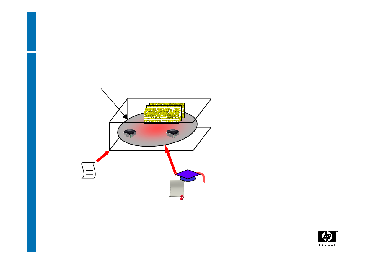
Trusted Building Block
CRTM
TCPA Specification
TSS
Software
TSS
Software
T
rusted
P
latform
(TP)
Specifies correct
operation
Certifies TP, TP Design,
Identities, Components
Certification
Authority
CA
CA
T
rusted
P
latform
S
ubsystem =
(T
rusted
P
latform
M
odule +
C
ore
R
oot of
T
rust for
M
easurement +
T
rusted platform
S
upport
S
ervice)
T
rusted
P
latform
S
ubsystem =
(T
rusted
P
latform
M
odule +
C
ore
R
oot of
T
rust for
M
easurement +
T
rusted platform
S
upport
S
ervice)
TPM

6
30 March, 2007
Static and Dynamic Roots of Trust for
Measurement
RTM is a function that executes on the platform
when the previous history of the platform can’t
affect the future of the platform
−
trusted to properly report to the TPM the first
software/firmware that executes after some sort
of reset
−
Static RTM is CPU after platform reset
−
Dynamic RTM is CPU after partition reset

7
30 March, 2007
The Core Root of Trust for
Measurement
- CRTM -
• The CRTM is the first piece of code that executes
on a platform at boot time. (eg. BIOS or BIOS
Boot Block in existing platform, or CPU program
on next generation platforms)
−
It must be trusted to properly report to the TPM
what is the first software/firmware that executes
after it
−
Only entities trusted by those who certify
behaviour can reflash the CRTM
8
30 March, 2007
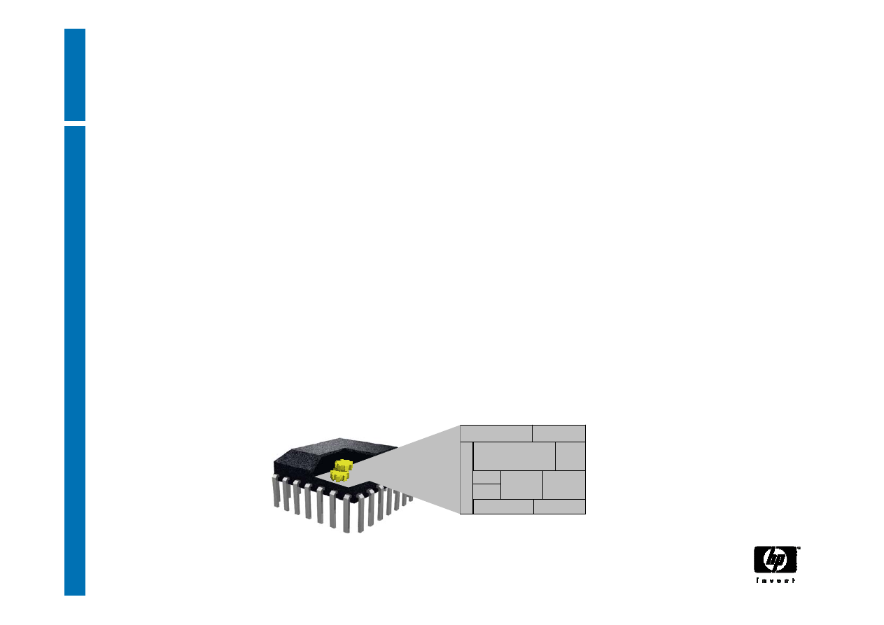
The Trusted Platform Module
- TPM -
• The TPM is the Root of Trust for Reporting. Think:
smartcard-like security capability embedded into
the platform
• The TPM is trusted to operate as expected
(conforms to the TCG spec)
−
The TPM is uniquely bound to a single platform
−
TPM functions and storage are isolated from all
other components of the platform (e.g., the CPU)
random number
generation
Non-volatile
Memory
Processor
Memory
asymmetric
key
generation
signing and
encryption
power detection
clock/timer
I/O
HMAC
hash

9
30 March, 2007
Trusted Platform Module
−
Protects keys in a platform, even when the
platform is switched off
−
Used indirectly to provide evidence that the
platform can provide isolated environments
10
30 March, 2007
TPM functions
hash
processor
NV memory
RNG
Asymmetric
key generation
memory
Power detection
Signing and
encryption
I/O
MAC
PCR
command
and command
source

11
30 March, 2007
TPM lifecycle
1. Set:
−
disable==FALSE
−
ownership==TRUE (redundant flag)
−
deactivated==TRUE
2. Execute TPM_takeOwnership to insert Owner’s
Auth value and create Storage Root Key SRK)
3. Set deactivated==FALSE
4. Use the TPM
5. Erase Owner’s Auth value via cryptographic use
of Owner’s Auth or Physical Presence
12
30 March, 2007
Creating random numbers
Internal
entropy source
mixer
one-way function
TPM_StirRandom
(entropy)
TPM_GetRandom

13
30 March, 2007
Endorsement Key
•One EK per TPM
• EK is a decrypting key, not a signing key
• used to recognise a platform (can’t be used to
identify a platform)
• Used to
• Assert ownership of a TPM
• Deliver pseudonymous identities to a TPM
14
30 March, 2007
Erasable Endorsement Keys
No EK
installed
EK
installed
erase=
{0:1}
TPM_CreateRevocableEK
(if erase==1)
TPM_RevokeTrust
Physical Presence
+ EKreset passwd
• RevokeTrust clears old TPM “personality” from TPM and
enables generation of new EK that is guaranteed to be private.
• Disadvantage: implicitly invalidates all existing attestation
15
30 March, 2007
TPM Endorsement certificate
String
"TCPA Trusted Platform Module Endorsement"
public Endorsement key
TPM type + TPM security properties
TPME reference
16
30 March, 2007
Platform Certificate
String
"TCPA Trusted Platform Endorsement"
Reference to endorsement credential
Platform type + platform security properties
PE reference
Reference to conformance credential

17
30 March, 2007
Platform Attestation
• TCG provides for a TPM to control “multiple
pseudononymous attestation identities”
• TPM attestation identity does not contain any owner/user
related information
−
It is a platform identity, to attest to platform properties
• A TPM uses attestation identities when proving that it is a
genuine (conformant to TCG) TPM, without identifying a
particular TPM
• Identity creation protocol allows choice of any (different)
Certification Authorities (Privacy-CA) to certify each TPM
identity, or use of DAA protocol
−
This prevents correlation

18
30 March, 2007
Attestation entities
•
Trusted Platform Module Entity (TPME) vouches that the
Trusted Platform Module (TPM) is genuine by attesting for
the Endorsement key inside the TPM
•
Validation Entity (VE) certifies the values of integrity
measurements that are to be expected when a particular
part of the platform is working properly
•
Conformance Entity (CE) vouches that the design of the
TCPA Subsystem in a class (type) of platform meets the
requirements of the TCPA specification
•
Platform Entity (PE) vouches for a platform containing a
specific TPM
•
Privacy Certification Authority (Privacy-CA; P-CA) attests
that an ID belongs to a TP
•
DAA issuer provides DAA credentials for a TPM
19
30 March, 2007
Platform Identity Certificate
String
"TCPA TPM Identity"
TPM identity chosen name
Platform type + platform security properties
Privacy-CA reference
String
TPM type + TPM security properties
TPM identity public key
20
30 March, 2007
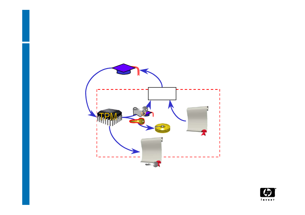
TPM Identity creation: Privacy-CA (1)
Certificates
Under Owner’s
control for Privacy
Identity
Certificate
Identity-binding
Identity
Certification Authority
Owner
Owner
CA
ABC
ABC
21
30 March, 2007
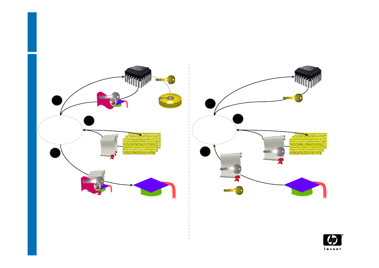
TPM Identity creation: Privacy CA (2)
TPM
TSS
Owner
3
TPM_MakeIdentity
TPM_ActivateIdentity
TSS_CollateIdentityRequest
Contact
Privacy-CA
1
5
4
2
Owner
TPM
TSS
TSS_Recover_TPM_identity
CA
Privacy CA
CA
Privacy CA
ID Binding
ID Key
ABC
ABC
Credentials
Encrypted
ID Proof
Session Key
TPMID
Encrypted
TPM_identity_credentials
TPM_identity_credentials
3
TPMID
1 – Request ID Certificate
2 – Retrieve ID Certificate

22
30 March, 2007
TPM Identity creation: DAA (1)
•
Direct Anonymous Attestation - DAA
•
A zero-knowledge method to prove that a platform
has attestation without revealing attestation
information
•
Introduced because of concerns about privacy,
and viability and trustworthiness of Privacy-CA
•
Provides a spectrum of pseudonymity because
need to audit and revoke rogue platforms
•
Allows revocation of compromised TPM keys

23
30 March, 2007
TPM Identity creation: DAA (2)
•
A verifier doesn’t see specific attestation
information issued to a platform, but believes the
platform has attestation and (optionally) can tell
whether the platform has previously communicated
with the verifier
24
30 March, 2007
DAA: infrastructure
Arbitrary number of DAA issuers:
any credible entity (almost certainly
including the platform OEM)
issuer
TPM_DAAjoin
TPM
verifier
Arbitrary number of
DAA verifiers
TPM_DAAsign
DAA issuer credentials
25
30 March, 2007
DAA: audit and privacy
1
Audit
trail
nonce ID
long-term ID
0
mid-term ID
Audit capabilities depend on selected DAA “name”
parameter
•Even long-term IDs provide (some) privacy
26
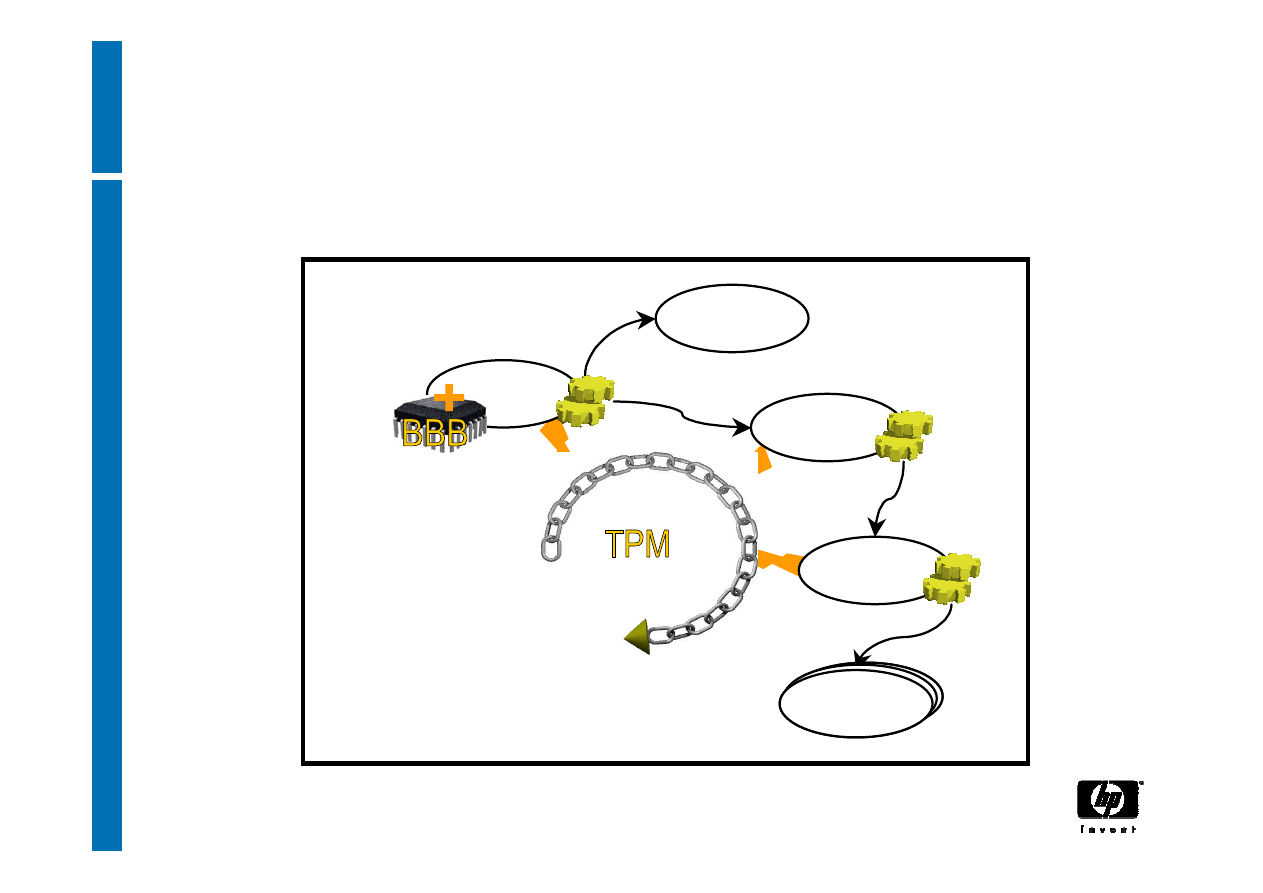
30 March, 2007
Authenticated Boot
BIOS
Measures
ROMs
Measures
Measures
Measures
Sends Value
Sends Value
Sends Value
Trusted PC Components
OS Loader
OS
Other Software
Components
Other Software
Components
OS Components
Other Software
Components
Other Software
Components
OS Components
Execution Order
Building Chain of Trust
27
30 March, 2007
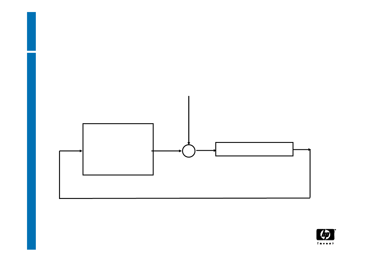
TPM Extend
input
+
Platform
Configuration
Register
Hash algorithm
append

28
30 March, 2007
Reporting integrity
• Measurements reported to the TPM during (and
after) the boot process cannot be removed or
deleted until reboot
• The TPM will use an attestation identity to sign
the integrity report
• The recipient of integrity information can evaluate
trustworthiness of the information based on the
certificate of attestation identity
Trust that the TPM is a genuine TPM on a
genuine Trusted Platform

29
30 March, 2007
Using integrity reports
• The recipient of reported information needs
“signed certificates” that prove that a given
measurement represents a known piece of code
−
Cert(BIOS v1.2 has hash value of H)
−
Cert(CorpIT config, combined hash value)
• The recipient can verify these Integrity Metrics
Certificates and compare certified metrics to
reported metrics
Trust that the reported metrics correspond to
certified software
Trusting the reported software is sole responsibility
of the recipient’s policy, for his application context

30
30 March, 2007
Protected Storage
• Not a generic bulk encryption device – no export
control problem
• Cryptographic keys can be created and protected
by the TPM
• Data/keys can be encrypted such that they can
only be decrypted using this TPM
• A specific software configuration can also be
specified, that will be required for the TPM to
allow data to be decrypted, or keys to be used
This is called “sealing”: parameters define the
Integrity Metrics to which the data should be
sealed
31
30 March, 2007
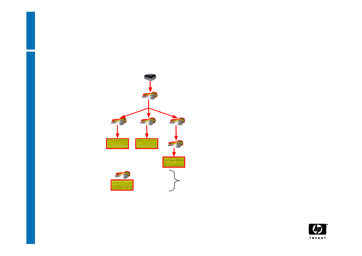
Storage Keys
TPM
Protects (Stored Internally)
Protects (Using encryption)
S
torage
R
oot
K
ey (Asym m etric key)
Signature
key
Signature
key
Protects (using encryption)
Protects (using encryption)
Storage key
Sym m etric key
Asym m etric
key
(signs data)
Authorization
secret
Secret
Data
Secret
Data
Secret
Data
Secret
Data
Asym m etric Keys
Arbitrary data
TPM Protected O bjects
Protected Storage Hierarchy
32
30 March, 2007
Creating keys
TPM_CreateWrapKey
RNG
asymm key generation
structure generation
Parent, key type,
authValue, releasePCRs
Public parameters
(plain text)
private parameters
(encrypted)
33
30 March, 2007
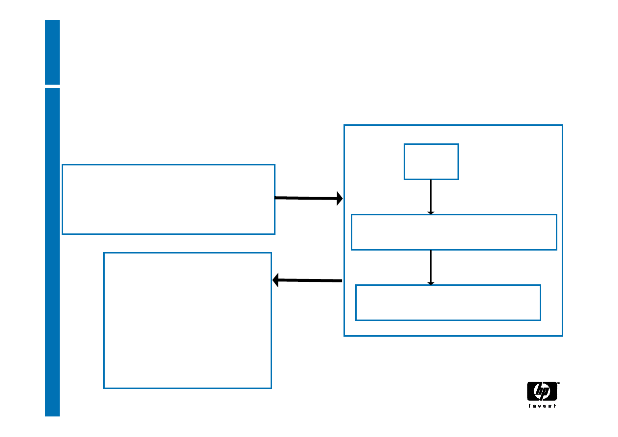
Encrypting data
TPM_Seal states the password and PCR values that must
be used to recover the data with TPM_Unseal
keyHandle
encAuth
pcrInfo
inData
sealedData
PCRsAtCreation
PCRsAtRelease
input
output
34
30 March, 2007
Decrypting sealed data
TPM_Unseal
keyHandle
BLOB
Check that PCR values
in BLOB match current
PCR values
data
PCRsAtCreation
35
30 March, 2007
Decrypting normal encrypted data
TPM_UnBind
keyHandle
BLOB
data
36
30 March, 2007
signing data
TPM_sign
keyHandle
Data
Signature scheme
signature value

© 2006 Hewlett-Packard Development Company, L.P.
The information contained herein is subject to change without notice
General Concepts of
Trusted Computing
Royal Holloway MSc in
Information Security
January 2007, Egham, UK
Graeme Proudler
Trusted Systems Laboratory, HP Labs, Bristol
UK

3
29 March, 2007
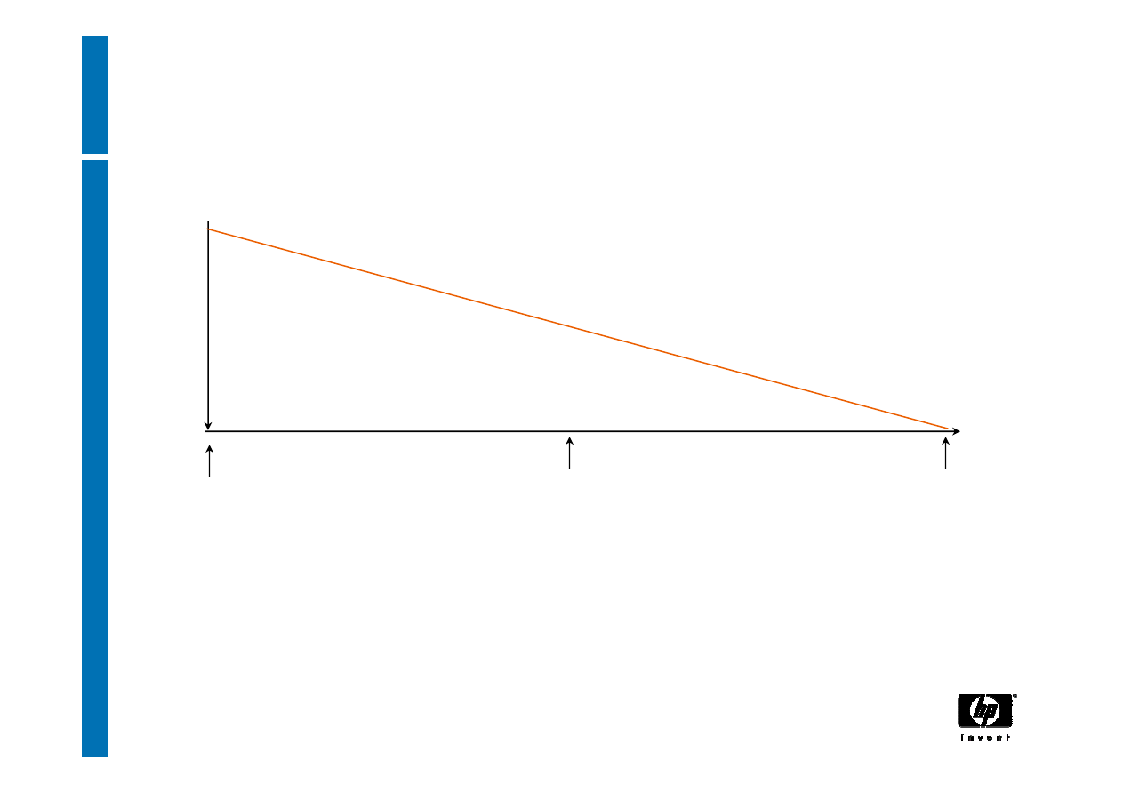
Time to change the Security horizon
•
Protect the soft core as well as the hard
perimeter
•
Build security in rather than bolt it on
•
Deploy a new model for trusted infrastructures
– platforms, operating systems, and
applications

4
29 March, 2007
Some of the reasons are:
• a “Catch-22”
•Cost
•Manageability
•Backwards compatibility
•Performance
•Migration
•Government import/export regulations
Why isn’t advanced security already
ubiquitous ?

5
29 March, 2007
Catch-22
•Many customers don’t know how they can
benefit from increased security
• Advanced security isn’t widely used because
it isn’t mainstream
• Advanced security isn’t mainstream because
isn’t widely used

6
29 March, 2007
Cost
•There’s corporate financial risk and personal
risk for employees in endorsing a new
technology
•Customers won’t buy unless the price is right
•Manufacturers won’t manufacture unless
there’s a return on the investment
•Mainstream computing platforms often have thin
profit margins

7
29 March, 2007
New technologies have new control surfaces,
which increase the cost and complexity of
owning that technology
•Customers want to be convinced that
advanced security technologies aren’t more
trouble than they are worth
•Manufacturers have to make it possible for the
IT department to manage the security
technologies in 50,000 unattended platforms at
03:00 hrs
Manageability

8
29 March, 2007
Existing applications must continue to work in
the presence of advanced security
mechanisms
•Customers can’t throw away their existing
investments
•New applications can’t be developed overnight
Backwards compatibility

9
29 March, 2007
Users will do everything they can to subvert
security mechanisms if the mechanisms get in
the way
•The security mechanisms must be simple to
use
•OSs must not load noticeably slower
•Applications must not execute noticeably
slower
Preferably advanced security mechanisms
make life simpler
•Less worry about losing data
•Less passwords to remember
•Greater privacy
Performance

10
29 March, 2007
What does “Secure” mean
“Secure” means that a platform has undergone a
security assessment
• It’s too expensive
• It’s too sensitive to changes
• It’s excessive for most commercial purposes

11
29 March, 2007
Why “Trusted Computing”?
•
We can’t (yet) do secure computing, but we still need to
protect data in critical information systems, to maintain and
improve confidence in use of the Internet
•
Trusted Platforms are computers optimised for the
protection and processing of private and secret data
•
Trusted Platforms have isolated environments that restrict
access to the data in those environments
•
Data in an environment are not necessarily safe and
secure, but only the applications in the same environment
can touch the data
Trusted Computing is a fundamental change to computers
and computing.

12
29 March, 2007
Trusted
“Trusted” means that a particular entity has decided
that a platform is "fit for some purpose"
• no need for security assessments of
applications
• Amortises the cost of the protection
mechanisms across all applications
• relies upon a Trusted Platform architecture
• uses small ubiquitous functions (Roots-of-
Trust plus kernel) that have undergone a
security assessment

13
29 March, 2007
Trusted Computing
•Brings aspects of High-Grade Security to
Commercial Mass-Market IT Systems at very low-
cost
•Provides a foundation for enforceable, owner-
controlled, security policies
•Provides a foundation for strengthened identity,
while protecting privacy
•Enables software integrity protection/detection
•Provides hardware protection for encryption key
storage

14
29 March, 2007
What’s the plan?
A Trusted Platform provides Separated Processing
Environments for critical functions
−
because we don’t know how to ensure that software
operates as implemented, unless it is separated
from possible interference (from other software
processes)
15
29 March, 2007
Trusted Platforms
Data-0
Application-a
Application-b
Data-1
Application-c
Application-d
Roots-of-Trust, VMM
Platform enforces policies using compartments and
• measurement and reporting of compartments
• protection of stored data outside compartments
• evidence that the platform has this architecture

16
29 March, 2007
Effects of Trusted Computing
• Fundamental changes to computers and
computing infrastructure resulting from the
distribution of trust
• Trusted Networking
• new methods of system authentication
• new uses of trusted resources
• protection for the GRID
•
You might not care where your data resides or
where it is executed.
17
29 March, 2007
Basic questions
Do I have
confidence in
interacting with this
platform?
Can I trust you to
be what you say
you are?
Can I trust you to
behave in an
expected manner?

18
29 March, 2007
What Trusted Platforms do
(1) Trusted Platforms provide data protection
mechanisms that enforce policies with hardware
(and software)
(2) An Owner controls the data protection
mechanisms and delegates their use
(3) Anyone with access to plaintext data and the data
protection mechanisms can dictate the
environment that must exist when that plaintext
data is processed
There’s no back-doors in the TCG design, and
TCG specifications explicitly prohibit back-doors

19
29 March, 2007
Why is it called “Trusted” Computing?
• Trusted Platforms contain technological
implementations of the factors that permit us, in
everyday life, to trust the behaviour of other
entities
• They enable you to verify that computers are able
to protect your private and secret data
• They help you prove that you comply with
(privacy) policies
−
You can provide information about a computer as a
means of demonstrating compliance to
individual/company policies

Trust is ….
Something can be trusted if it behaves in an expected manner
in given circumstances
All trust is ultimately derived from people (and hence
organisations)

21
29 March, 2007
Trust is an expectation of behaviour
•
Trusted Platforms use technological
implementations of the methods and factors that
we use, in everyday life, to trust the behaviour of
others
−
we use those methods and factors instinctively, and
most of us have never consciously thought about them

22
29 March, 2007
What’s necessary for trust?
It is safe to trust something when
•
(it can be unambiguously identified)
•
&
(it operates unhindered)
•
&
([the user has first hand experience of
consistent, good, behaviour]
or
[the user trusts
someone who has provided references for
consistent, good, behaviour])

23
29 March, 2007
Unambiguous identification
•People need to recognise things in order to be
able to trust them (we recognise a person’s looks,
voice and walk, for example)
•Trusted platforms identify themselves (via
cryptography) and the software in use (via
measurements)

24
29 March, 2007
Unhindered operation
•A person might not behave normally if the
environment is adversely affecting him (we check
that people don’t have guns pointed at them, for
example)
•Trusted Platforms isolate processes, because
we don’t know how to ensure that a process
operates as implemented unless it is isolated
from other processes

25
29 March, 2007
References
•In the absence of personal experience, people
need references in order to be able to trust
something
•Trusted platforms include references
(attestation) for the platform and for the software
that executes on the platform

26
29 March, 2007
Trusted Platforms use Roots-of-Trust
•
A Root-of-Trust is a component that must behave
as expected, because its misbehaviour cannot be
detected
•
A Trusted Platform Module (TPM) is an
implementation (normally a single chip) of (some)
roots-of-trust
•
The Trusted Computing Group has created
specifications for V1.1 and V1.2 TPMs

27
29 March, 2007
Trusted Platforms provide separation of
privileges
•
Trusted Platforms provide data protection
mechanisms that enforce policies
• The platform owner controls the data protection
mechanisms and delegates their use
• A data owner can use the data protection mechanisms
to dictate the environment that must exist when
plaintext data is processed

28
29 March, 2007
Trusted Platforms use standard crypto
•
Security chip (TPM) provides asymmetric encrypt/decrypt
function-calls
−
TPM uses 2048bit-RSA for TCG system operations
−
TPM may use additional asymmetric crypto algorithms
but mandated RSA guarantees interoperability
•
TPM uses symmetric-encryption for TCG system
operations but not required to provide symmetric
encrypt/decrypt function-calls
•
All bulk (symmetric) encryption is done on the host
platform (the main CPU)
−
Enables vendor/user /country choice of algorithm
−
Provides best performance when encrypting files and
messages

29
29 March, 2007
Ordinary Trusted Platforms won’t be
designed to protect “nuclear launch
codes”
TCG’s standard algorithms are intended for
commercial use: they may not be suitable
when processing information affecting national
security

30
29 March, 2007
No BORE
•
It’s impossible to stop a sophisticated attacker
from breaking a particular trusted platform and
accessing the secret and private data on that
platform
•
But TCG trusted platforms don’t have global
secrets and hence prevent break-once/read-
everywhere attacks

31
29 March, 2007
Trusted Platforms are privacy-positive
• There’s no privacy without strong data protection!
• The technology has peculiar features that exist only to
support privacy
−
Security mechanisms delivered “turned-off” (or “turned
on”, as customer wishes)
• complex controls to permit mutually incompatible
settings
• features to mitigate that complexity
−
Platform Identification requires explicit permission of
platform owner
• multiple pseudonymous identities limit correlation of
transactions

32
29 March, 2007
Trusted Platforms are Owner controlled
• The platform Owner controls the data protection
mechanisms, although these controls can be
delegated to other people, to wizards, and to
trusted software
• No one else controls the data protection
mechanisms
−
not the platform manufacturer
−
not software vendors
−
not TCG
−
not the government
−
not the …

33
29 March, 2007
Trusted Computing is an open design
TCG technology:
• is platform independent (PCs, servers, PDAs,
mobile ‘phones …)
• is OS independent
• can be implemented in many different ways
• doesn't prevent execution of any software
• doesn't use software or data signed by TCG
−
there's no "TCG master key”

34
29 March, 2007
TCG specifications are open
•
The Trusted Computing Group’s specifications
can be inspected by any (knowledgeable and
competent) person
•
Independent labs can inspect and certify a
manufacturer’s Trusted Platform design

35
29 March, 2007
Customer benefits
• greater confidence in computer services
−
First generation Trusted Platforms (now): hardware
based crypto API, protected store for secrets
−
First generation Trusted Platforms (future): hardware
based crypto API, protected store for secrets, safe
recognition of platforms
−
Second generation Trusted Platforms (future):
hardware based crypto API, protected store for secrets,
safe recognition of platforms, hardware enforced
isolated execution environments for applications

36
29 March, 2007
It’s too much of change to get there in a single
step
•Advanced security technologies (like any new
technology) have to be introduced in steps
•Each step has to introduce its own benefits, or
customers won’t buy it
Migrating the market place

37
29 March, 2007
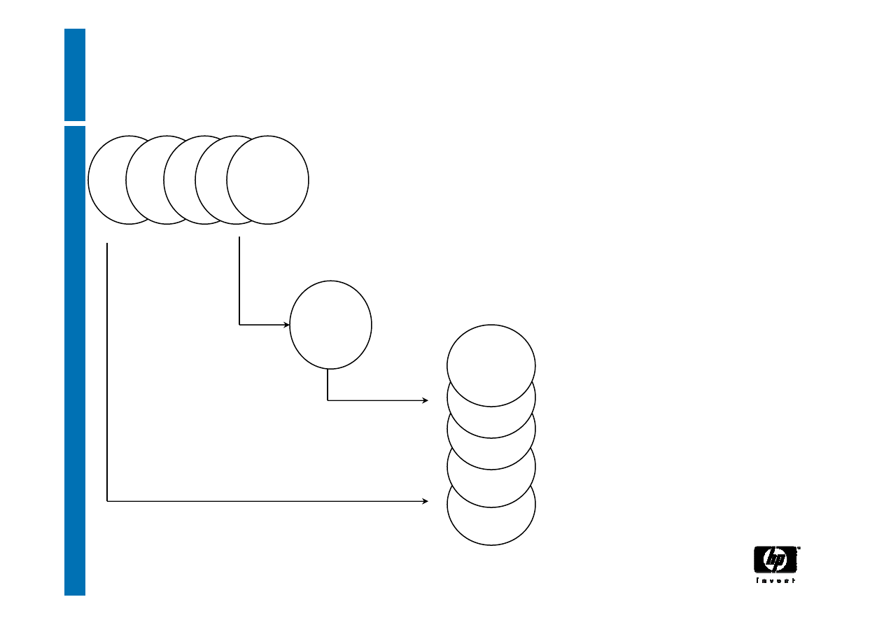
Trusted Computing road map
Tier 3
TPM Hardware
availability
Tier 0
HW Platform
Root-of-Trust
TC Operating
Environment -
Chain-of-Trust
Tier 1
TC Apps –
Enterprise,
Biz. Critical,
Other
Tier 2
Trusted
Ecosystems
Inc
rea
sed
in
teg
rat
ion
,
Inc
rea
sin
g v
alu
e pr
op
os
ition

38
29 March, 2007
Short term benefits – protected storage
−
Customers can encrypt the data on their hard disks in a way that is
much more secure than software solutions
−
standard crypto-API access to an embedded hardware
chip (TPM) for existing applications that do not speak
“TCG”
• (True) Random Number Generator
• Portal to (unlimited amounts) of encrypted storage
−
No master key stored on disk
−
No password derivatives stored in plain text
−
digital signature keys (includes identity keys) can be
protected and used within the embedded hardware chip

39
29 March, 2007
Middle term benefits – integrity
checking
•
Automatic prevention of access to information if
undesirable programs are executing
• TCG technology enables measurement of the
software environment on a platform. Hence:
• Enhanced data confidentiality through
confirmation of platform integrity prior to
decryption (only decrypt or permit access to
secrets if the software environment is what
was intended)

40
29 March, 2007
Long term benefits – e-commerce
•
Customers and their partners/suppliers/customers
can connect their IT systems and expose only the
data that is intended to be exposed
• platform identities and integrity metrics can be
proven reliably to previously unknown parties
• Secure online discovery of platforms and
services: confidence in information about the
software environment and identity of a remote
party, enabling higher levels of trust when
interacting with this party

41
29 March, 2007
Commercial Constraints on Trusted
Computing
•
(cost) the technology must be low cost in order to be
included in common forms of computing platform
•
(backwards compatibility) existing applications must
execute on trusted platforms without modification
•
(government import/export regulations) cryptographic
hardware mustn’t do bulk encryption
•
(maintain performance) make as much use of the main
platform CPU as possible, because people will not use a
service that is slow
•
(incremental advantages) the full benefits of trusted
computing cannot be delivered all at once because too
many changes are required, so a staged evolution is
necessary, yet each stage must deliver its own value or
customers will not purchase it.

42
29 March, 2007
Generally, government have relaxed their
regulations on the import and export of
cryptographic equipment
It’s still commercially prudent to be flexible in
choice of bulk encryption algorithm
Government import/export regulations

43
29 March, 2007
Rebuttal to published concerns
• A TPM is passive
−
It doesn’t enforce policy decisions
−
it doesn’t stop the execution of software
• Applications don’t require TCG certification to run
on trusted platforms
• TCG technology isn’t DRM (although it could be a
component in a DRM system)

44
29 March, 2007
Real social concerns
•
If you have a platform that protects information,
should a third party be able to use that
mechanism in your computer to protect the third
party’s information from you?
•
How will open-source self-certify software
distributions, to say that these distributions will
“do the right thing”?
•
Will owners of commercial data trust open-source
software distributions?
•
What if Trusted Platforms are used merely to
restrict choice, in circumstances where no data
protection is really required?

45
29 March, 2007
Acceptance of Trusted Platforms
TCG specifications have been studied by
• Various governments’ privacy commissions
• The EU
• The EFF
−
they are happier with some features than with
others

46
29 March, 2007
•Ubiquitous platform security mechanisms
•More capable management mechanisms
•New platform architectures and network
properties
•Increased use of virtualisation
•Increased resistance to attack
•Greater privacy
•We might not care where our data is stored or
where it is executed
•The GRID
•Software Agents
Summary-1

47
29 March, 2007
Summary-2
•
TCG Trusted Computing enables you to trust a
computer using the same methods that you use
in everyday life, when deciding whether to trust
something.
•
All trust, even that in a Trusted Platform, is still
ultimately derived from people
Trusted Computing IY5608:
The Roots of Trust - The RTM and the
TPM
Eimear Gallery
Royal Holloway, University of London
e.m.gallery@rhul.ac.uk
www.opentc.net
26th January 2007
2
Current platforms with
integrated TPMs
Hardware
Operating system
Applications
Data
TPM
www.opentc.net
26th January 2007
3
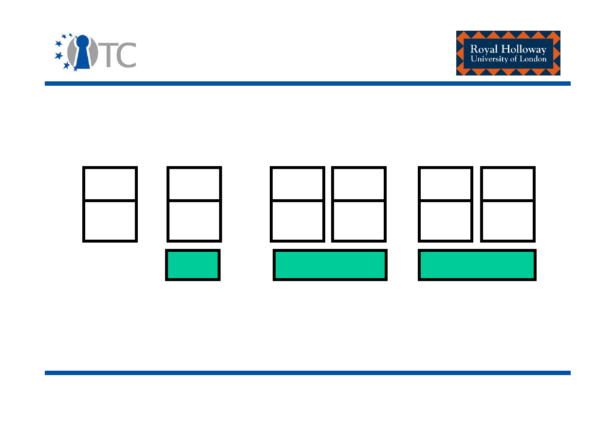
Envisaged trusted platforms
(stage 1)
Hardware
Operating system
Applications
Data
TPM
CRTM
www.opentc.net
26th January 2007
4
Envisaged trusted platforms
(stage 2)
Hardware
Virtual machine monitor/ Hypervisor/ Isolation layer
Data-1
Application-a
Application-b
Guest OS
TPM
CRTM
Data-2
Application-c
Application-d
Guest OS
www.opentc.net
26th January 2007
5
Envisaged trusted platforms
(stage 3)
Hardware (including hardware support for isolation –
CPU, chipset, keyboard, mouse, video graphics card
extensions)
Virtual machine monitor/ Hypervisor/ Isolation layer
Data-1
Application-a
Application-b
Guest OS
TPM
Data-2
Application-c
Application-d
Guest OS
CRTM and DRTM

www.opentc.net
26th January 2007
6
Fundamental security services
provided by a future trusted
computing framework
• Attestation – provides remote assurance of the state of
the hardware and software environment running on a
computing platform.
• Isolation – execution environments/ domains/
compartments.
• Secure storage:
– Encryption;
– Sealing.
• Secure I/O.
www.opentc.net
26th January 2007
7
Focus of lecture 2 and 3
Hardware
TPM
RTM

www.opentc.net
26th January 2007
8
The TCG main specifications
and other reference material
• Siani Pearson (editor), Trusted Computing Platforms: TCPA
Technology in Context, Hewlett-Packard Company, 2003.
• TCG Specification Architecture Overview, Revision 1.2.
• TCG TPM Main Specification (General Platform Specification)
Version 1.2:
– Design principles;
– Structures of the TPM;
– TPM commands.
• TCG PC Client Specific Implementation for Conventional BIOS,
Version 1.2.
www.trustedcomputinggroup.org

www.opentc.net
26th January 2007
9
Trust (re-visited)
• Trust is an expectation of behaviour.
• Trusted platforms use technological implementations of
the methods and factors that we use, in everyday life, to
trust the behaviour of others.
– We use those methods and factors instinctively, and most
of us have never consciously thought about them.

www.opentc.net
26th January 2007
10
What is necessary for trust?
(Graeme Proudler, HP)
It is safe to trust something when:
• (it can be unambiguously identified);
•
&
(it operates unhindered);
•
&
([the user has first hand experience of consistent,
good, behaviour]
or
[the user trusts someone who
has provided evidence/references for consistent,
good, behaviour]).

www.opentc.net
26th January 2007
11
Unambiguous identification
• People need to recognise things in order to be able to
trust them (we recognise a person’s looks, voice and
walk, for example).
• Trusted platforms identify:
1. Themselves (via cryptography); and
2. The software in use (via measurements).

www.opentc.net
26th January 2007
12
Unhindered operation
• A person might not behave normally if the environment
is adversely affecting him (we check that people don’t
have guns pointed at them, for example).
• On a trusted platform:
1. TPM – physically tamper evident; and update of TPM or
CRTM code or data must only be permitted by authorised
entities in a controlled manner.
2. Processes can be isolated – because we don’t know how
to ensure that a process operates as implemented unless
it is isolated from other processes.

www.opentc.net
26th January 2007
13
First hand experience; or
Evidence/references
• In the absence of personal experience, people need
references in order to be able to trust something.
• Trusted platforms:
1. Include references for the platform hardware; and
2. Generate evidence/references for the software that
executes on the platform.
(Both can be to a challenger of the platform – someone who
wishes to make a decision about whether to trust the
platform for a particular purpose – platform attestation.)

www.opentc.net
26th January 2007
14
Trusted platform foundation-
The roots of trust
• A
Root-of-trust
is a component that must behave as
expected, because its misbehaviour cannot be detected.
• Roots of trust enable the gathering, storage and
reporting of evidence/references about the
trustworthiness of software environment running on the
platform.
• They represent the components of a TP which must be
implicitly trusted if the evidence/references are to be
trusted.

www.opentc.net
26th January 2007
15
The roots of trust
• A
Root of Trust for Measurement (RTM)
– The
component that can be trusted to reliably measure the
software/firmware which executes after some sort of
reset (either platform or partition).
• A
Root of Trust for Reporting (RTR)
and a
Root of
Trust for Storage (RTS)
– The components that can
be trusted to store and report reliable information about
the platform.

www.opentc.net
26th January 2007
16
Roots of trust - Implementation
• The Core Root of Trust for Measurement (
CRTM
) and
the Dynamic Root of Trust for Measurement (
DRTM
) are
the roots of trust for measurement.
• The
TPM
is the root of trust for reporting and the root of
trust for storage.

www.opentc.net
26th January 2007
17
The CRTM
• The
CRTM
is the static root of trust for measurement.
• For the foreseeable future, it is envisaged that the
static-RTM will be integrated into the normal computing
engine of the platform, where the provision of additional
BIOS boot block or BIOS instructions (the CRTM) cause
the main platform processor to function as the RTM.
• Static RTM is CPU after platform reset.

www.opentc.net
26th January 2007
18
The DRTM
• A RTM is a function that executes on the platform when
the previous history of the platform cannot affect the
future of the platform.
• Trusted to properly measure the first software/firmware
that executes after some sort of reset and report this
integrity measurement to the TPM.
• In a traditional system architecture – this function
executes after a platform reset.
• With the advent of system partitioning/compartment
isolation – boot process is no longer linear.

www.opentc.net
26th January 2007
19
The DRTM
• Isolated execution environments/system partitions may
be brought up and taken down:
– The history of a the platform prior to launch of the isolation
layer cannot effect the future of the isolation layer; or,
indeed,
– Any previous compartment/ isolated execution
environment cannot effect the future of any isolated
compartments/ execution environments.
• With this, the concept of a dynamic RTM was
introduced.
• Dynamic RTM is CPU after partition reset.
www.opentc.net
26th January 2007
20
The DRTM
For example – Intel DRTM
(described: David Grawrock, The Intel Safer Computing Initiative:
Building Blocks for Trusted Computing, Intel Press, 2006)
OS
Apps
OS
Apps
OS
Apps
OS
Apps
OS
Apps
VMM
VMM
VMM
DRTM – Measures the VMM prior to its launch.
Events occurring prior to the VMM launch do not effect the launch.

www.opentc.net
26th January 2007
21
The TPM
• The
TPM
is the root of trust for storage and the root of
trust for reporting.
• Normally implemented as a single chip.
• Specifications exist for both v1.1 and v1.2 TPMs:
– We will focus on v1.2 TPMs.
• TPM functions and storage are isolated from all other
components of the platform (e.g. the CPU).
• Each TPM is bound to a single platform.
www.opentc.net
26th January 2007
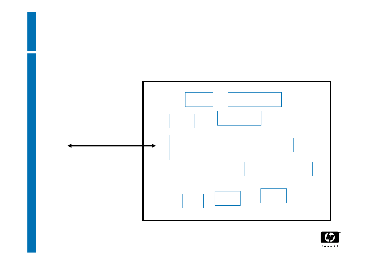
22
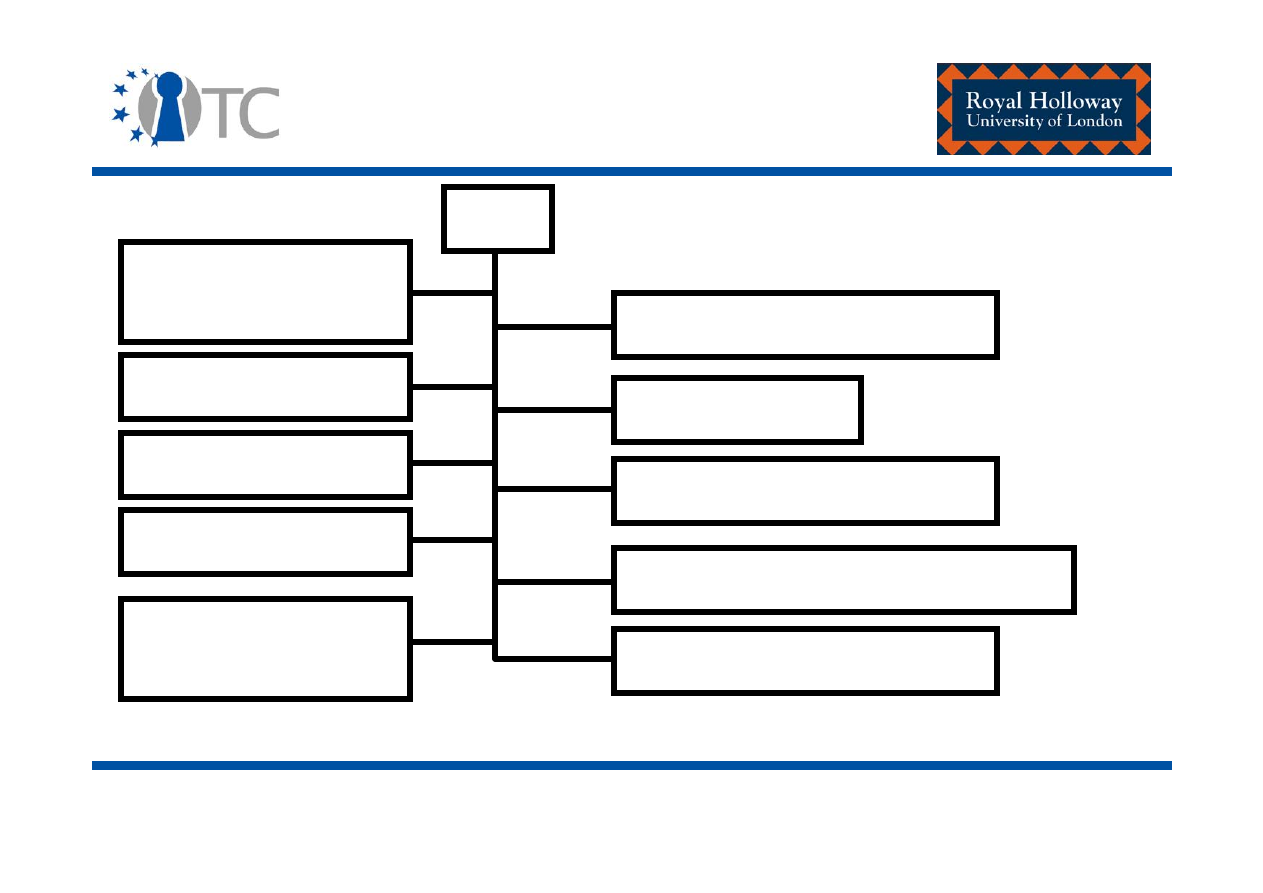
The TPM components
I/O
HMAC engine
Cryptographic
co-processor
Key generation
RNG
Power detection
Execution environment
Volatile memory
SHA-1 engine
Opt-in
Non-volatile
memory

www.opentc.net
26th January 2007
23
TPM – Input and output
• Manages flow of information over the communications
bus.
• It performs encoding/decoding suitable for internal and
external buses.
• It routes messages to the appropriate components
within the TPM.
• The I/O component enforces access control associated
with TPM functions requiring access control.

www.opentc.net
26th January 2007
24
TPM – Cryptographic co-processor
• Asymmetric encryption/decryption
– The TPM must support RSA;
– The TPM must use RSA for encryption/decryption;
– The TPM may implement other asymmetric algorithms for
asymmetric encryption/decryption, such as elliptic curve.

www.opentc.net
26th January 2007
25
TPM – Cryptographic co-processor
• Symmetric encryption/decryption engine
– Symmetric encryption is used by the TPM to:
• Provide confidentiality of newly created authorisation data
being sent to the TPM;
• Provide confidentiality during transport sessions;
• Provide internal encryption of blobs stored off the TPM.
– For authentication and transport sessions:
• Stream cipher - XOR is used;
• Key generation process is also specified in both cases (re-
visited later).

www.opentc.net
26th January 2007
26
TPM – Cryptographic co-processor
– For internal encryption of blobs stored off the TPM:
• The TPM designer may choose any symmetric algorithm.
– Symmetric encryption is not exposed for general message
encryption.

www.opentc.net
26th January 2007
27
TPM – Cryptographic co-processor
• Signature operations
– The TPM must support the RSA algorithm for signature
operations, where signed data must be verified by entities
other than the TPM which performed the sign operation.
– The TPM may use other algorithms for signature
generation, e.g. DSA, but there is no requirement that
other TPM devices either accept or verify those signatures.

www.opentc.net
26th January 2007
28
TPM – Key generation
• The TPM must generate RSA key pairs.
– The TPM must support key sizes of 512, 768, 1024 and
2048 bits (minimum recommended = 2048 bits);
– It is mandated that certain keys (the storage root key and
attestation identity keys, for example) must be at least
2048 bits.
• The implementation must be in accordance with P1363-
Standard specifications for public-key cryptography:
http://grouper.ieee.org/groups/1363/

www.opentc.net
26th January 2007
29
TPM – HMAC engine
• The HMAC engine is also used in the authorisation
mechanism:
– Allows a TPM to verify that a caller knows the required
authorisation data to complete a particular action – for
example, to utilise a particular command or to access a
particular key or piece of data.
– It also enables the TPM to verify that no unauthorised
modifications have been made to an incoming command in
transit.

www.opentc.net
26th January 2007
30
TPM – RNG
• Comprised of three components:
– Entropy source and collector;
– State register; and
– A mixing function.
• Entropy source and collector
– Entropy source: is the process or processes which provide
entropy.
• Sources include noise, clock variations, for example.
– The collector: is the process that collects the entropy,
removes the bias and smoothes the output.
• For example, if the raw entropy data has a bias of 60% 1s
and 40% 0s then the collector takes this information into
account before sending data to the state register.

www.opentc.net
26th January 2007
31
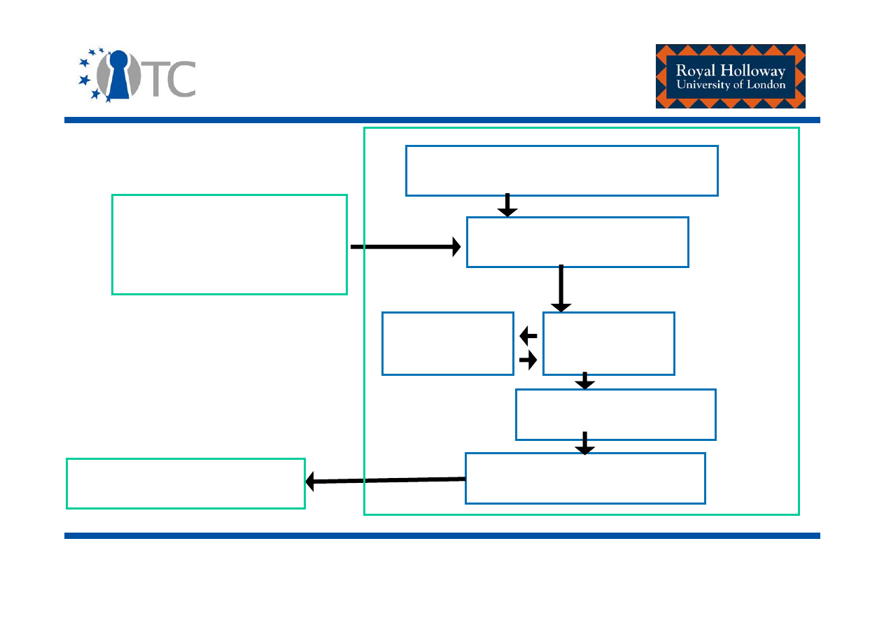
TPM – RNG
• State register
– Where the output from the entropy collector is stored.
– The implementation may use 2 registers – a non-volatile
and a volatile:
• The state of non-volatile register is stored to the volatile
register on start-up.
• Changes to the state of the state register from either the
entropy source or mixing function affect the volatile register.
• The state of the volatile register is stored to the non-volatile
register at power down.
• Avoids overuse of flash.
• Mixing function
– Takes the state register and produces the RNG output.
www.opentc.net
26th January 2007
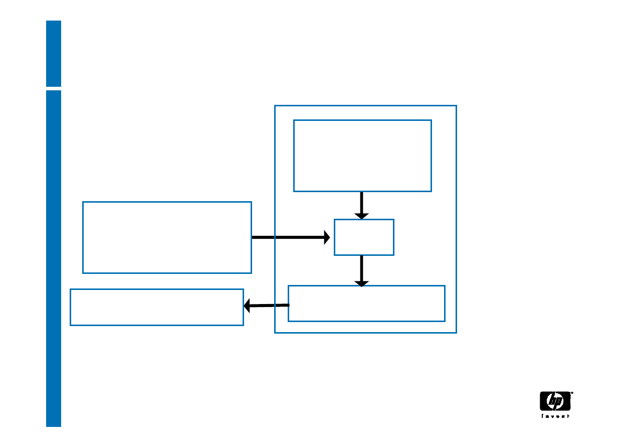
32
TPM – RNG
Internal entropy source
Entropy collector
One-way function)
TPM_StirRandom
(entropy)
TPM_GetRandom
Volatile state
register
Mixing function
Non-volatile
state register

www.opentc.net
26th January 2007
33
TPM – SHA-1 engine
• The TPM must implement the SHA-1 hash algorithm as
defined in FIP-180-1.
• The output of SHA-1 is 160 bits and all areas that expect
a hash value must support the full 160 bits.
• Security issue – significant weaknesses have been
discovered in SHA-1.
– (Future version of the TPM specifications – SHA-256, SHA-
384, and SHA-512 – TPM v1.3??).

www.opentc.net
26th January 2007
34
TPM – Opt in
• The opt-in component provides mechanisms to allow the
TPM to be turned on/off, enabled/disabled,
activated/deactivated.
• This component also maintains the state of persistent
and non-volatile flags and enforces the semantics
associated with these flags.
– Example (permanent flags):
• TPM_PF_DISABLE – default value of TRUE – TPM is
disabled.
• TPM_PF_OWNERSHIP – default value of TRUE – an
(unowned) TPM is ready to accept an owner.

www.opentc.net
26th January 2007
35
TPM – Execution engine
• Runs the program code to execute TPM commands
received from the I/O port.

www.opentc.net
26th January 2007
36
TPM – Non-volatile memory
• Non-volatile memory is used to store persistent identity
and state information associated with the TPM.
– Sample data stored – the endorsement key.
• Must also support the functionality of a Data Integrity
Register (DIR):
– The TPM must provide one 20-byte non-volatile register
called a DIR.
– The TPM may support more that one DIR.
(The potential use of such a register is discussed later).

www.opentc.net
26th January 2007
37
TPM – Platform Configuration
Registers (PCRs)
• A PCR is a 160-bit/20-byte storage location which is
used to store integrity measurements.
• A TPM must support a minimum of 16 PCRs.
• Whether a PCR must be used to store a specific
measurement (e.g. the CRTM, BIOS…Option ROM
code…), or, whether it is available for general use, is
specified in platform specific specifications.

www.opentc.net
26th January 2007
38
The endorsement key
• An 2048-bit RSA asymmetric key pair located in a TPM’s non-
volatile memory.
• A TPM has one such endorsement key pair.
• The private key from this key pair is used for decryption;
never for signature operations.
– It is never exposed outside of the TPM.
• The public key from this pair may be exported outside the
TPM to be used by external entities.
– Used to assert ownership over a TPM;
– Also used to deliver pseudonymous identities/attestation
identities to a TPM.

www.opentc.net
26th January 2007
39
Endorsement key - Creation
• The manufacturer can “squirt” an endorsement key pair
into a TPM.
– Generated using an external key generator.
• Alternatively, the TPM_CreateEndorsementKeyPair may
be used.
– This causes the TPM to generate a TPM endorsement key
pair.
– This command returns a failure code if an endorsement
key already exists.
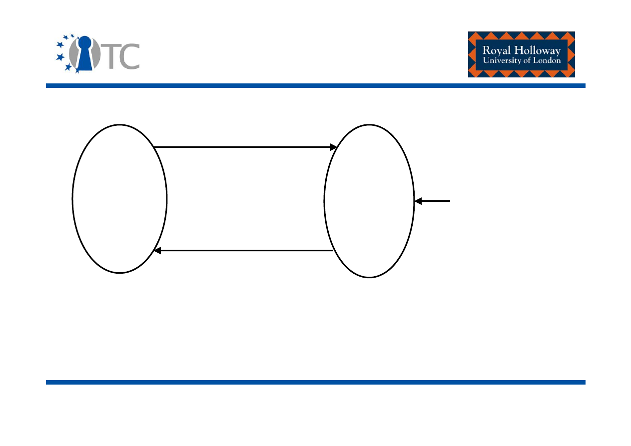
www.opentc.net
26th January 2007
40
Endorsement key – Creation –
Erasable endorsement keys
No EK
installed
EK
installed
erase=
{0:1}
TPM_CreateRevocableEK
(if erase==1)
TPM_RevokeTrust
Physical Presence
+ EKreset passwd
• RevokeTrust clears old TPM endorsement key from TPM and
enables generation of new EK that is guaranteed to be private.
• Disadvantage: implicitly invalidates all existing attestation.

www.opentc.net
26th January 2007
41
Attestation entities
1. A Trusted Platform Module Entity (TPME) attests to the fact
that the TPM is genuine:
•
Digitally signs an endorsement credential containing the public
endorsement key belonging to a particular TPM.
•
The TPME is likely to be the TPM manufacturer.
2. A Conformance Entity (CE) vouches that the design of the
TCG Subsystem in a class (type) of platform meets the
requirements of the TCG specification.
3. A Platform Entity (PE) offers assurance in the form of a
platform credential that a particular platform is an
instantiation of a TP design, as described in conformance
credentials, and that the platform's TPM is indeed genuine.
www.opentc.net
26th January 2007
42
Endorsement credential
• Certifies that a public endorsement key belongs to a genuine
TPM.
• Constructed by: TPME.
String
"TCPA Trusted Platform Module Endorsement"
public endorsement key
TPM type + TPM security properties
TPME reference

www.opentc.net
26th January 2007
43
Conformance credentials
• Certify that the design of the TCG Subsystem in a class
(type) of platform meets the requirements of the TCG
specification.
• Multiple conformance credentials may be issued for a
single platform - one for the TPM and others for the
CRTM, connection of the CRTM storage to the
motherboard and the connection of the TPM to the
motherboard, for example.
www.opentc.net
26th January 2007
44
Platform credential
• Certifies
that a particular platform is an instantiation of a TP
design, as described in conformance credentials, and that the
platform's TPM is indeed genuine
:
– Certifies that a particular trusted platform is genuine;
– Constructed by: Platform entity.
String
"TCPA Trusted Platform Endorsement"
Reference to endorsement credential
Platform type + platform security properties
PE reference
Reference to conformance credentials

www.opentc.net
26th January 2007
45
Initialising the TPM
• TPM_Init transitions the TPM from a power-off state to
one where the TPM begins an initialisation process.
• TPM_Init could be the result of power being applied to
the platform or a hard reset.

www.opentc.net
26th January 2007
46
Limited self testing
• After initialisation the TPM performs a limited set of self
tests on a minimal set of TPM commands to ensure that
they are working properly.
• Commands include:
– TPM_SHA1xxx: The TPM SHA1 commands
– TPM_Extend
– TPM_Startup
– TPM_ContinueSelfTest
– TPM_SelfTestFull
– TPM_GetCapability

www.opentc.net
26th January 2007
47
Starting-up the TPM
• TPM_Startup transfers the TPM from an initialisation state to a
limited operational state.
– (always preceded by TPM_Init)
• The platform informs the TPM of the required platform
operation state by inputting one of the following values into
the ‘startupType’ parameter of the TPM_Startup command.
– ‘Clear’ results in the TPM values being set to a default or non-
volatile operational state.
– ‘Save’ causes the TPM to recover state, including PCR values,
saved to non-volatile memory following the successful execution
of the TPM_SaveState command.
– ‘Deactivated’ informs a TPM that any further operations should
not be allowed. The TPM turns itself off and can only be reset by
performing another TPM_Init command.

www.opentc.net
26th January 2007
48
Complete self testing
• Finally, the TPM is transformed to a fully operational
state, after the successful completion of all remaining
self-tests.
– The TPM_ContinueSelfTest command is issued during
platform initialisation.
• It causes the TPM to test all the TPM internal functions that
were not tested at start-up.
• If the TPM is running in compliance with FIPS-140 evaluation
criteria, then the TPM_ContinueSelfTest command will request
that the TPM perform a complete self-test.
– Another complete self-test of the TPM capabilities can be
explicitly requested, using the TPM_SelfTestFull command.

www.opentc.net
26th January 2007
49
Fully operational
• Following initialisation, start-up and self-testing the TPM
is transformed into a fully operational state.
• However, not all TPM functions are available until the
TPM acquires an owner.

www.opentc.net
26th January 2007
50
Enabling the TPM
• A TPM must be enabled so that the process by which a
prospective owner takes ownership of the TPM can be
completed.
• A single non-volatile TPM flag, pFlags.tpmDisabled, is used
to represent the enablement status.
• This flag cannot initially be changed to
pFlags.tpmDisabled = FALSE with normal computer
controls. It may only be changed via the execution of the
physical command TPM_PhysicalEnable, which may be
achieved by flicking a dedicated switch on the platform.

www.opentc.net
26th January 2007
51
Enabling the TPM
• The effect of physically enabling the TPM persists
between boot cycles.
• Just as TPM_PhysicalEnable physically enables a TPM,
TPM_PhysicalDisable physically disables a TPM.
• Both of these commands may be used by anyone who
can prove that they are physically present at the
platform, for example by accessing and changing a
dedicated switch or jumper, either before or after the
TPM has acquired an owner
.

www.opentc.net
26th January 2007
52
Enabling/Disabling the TPM
• TPM_OwnerSetDisable is used to put a TPM into either
an enabled or a disabled state after the TPM has
acquired an owner.
• Input of the correct TPM owner authorisation data
(password) is required, before this command can be
executed.
• Once ownership has been established, disabling the TPM
causes all TPM functionality to be turned off, with the
exception of PCR value tracking.
– In this way, the TPM always has an accurate record of the
platform state.

www.opentc.net
26th January 2007
53
Enabling ownership of the TPM
• The fFlags.OwnershipEnabled flag must be set to TRUE if
the process by which a prospective owner can take
ownership is to succeed.
• A single non-volatile TPM flag is used to represent the
ownership enabled status.
• This flag must be changed using the
TPM_SetOwnerInstall command which requires a
physical presence at the platform.
• After the TPM has an owner, the status of this flag has
no effect.

www.opentc.net
26th January 2007
54
Taking ownership of the TPM
• The TPM_TakeOwnership command is utilised.
1. Twenty bytes of TPM owner authorisation data, which is
to be shared between the owner and the TPM, is
inserted into the TPM under the protection of the TPM's
public endorsement key.
• This data is labelled the ‘owner authorisation secret’ and will
enable the TPM owner to gain access to TPM commands that
require the owner authorisation data to be input before they
are executed.
–
This are called owner authorised commands. Examples include:
TPM_MakeIdentity and TPM_ActivateIdentity commands, defined
later in this presentation.

www.opentc.net
26th January 2007
55
Taking ownership of the TPM
2. The owner then informs the TPM which type of
asymmetric key to create as the storage root key.
3. The authorisation secret for the SRK is sent to the TPM
under the protection of the TPM's public endorsement
key.
4. The TPM then generates a nonce (tpmProof), i.e. a 160-
bit secret value.

www.opentc.net
26th January 2007
56
Taking ownership of the TPM
• This nonce is later associated with non-migratable TPM
key objects by the TPM, so that, when this value is later
found associated with a particular TPM key, the TPM
knows that it generated the key.
– Non-migratable TPM keys are:
• Created inside the TPM;
• Locked to an individual TPM;
• Never duplicated;
• Never available in plaintext outside of the TPM.
• The owner's authorisation secret, the private part of the
SRK, the SRK's authorisation secret, and the nonce,
tmpProof, are all kept in non-volatile storage in the TPM.
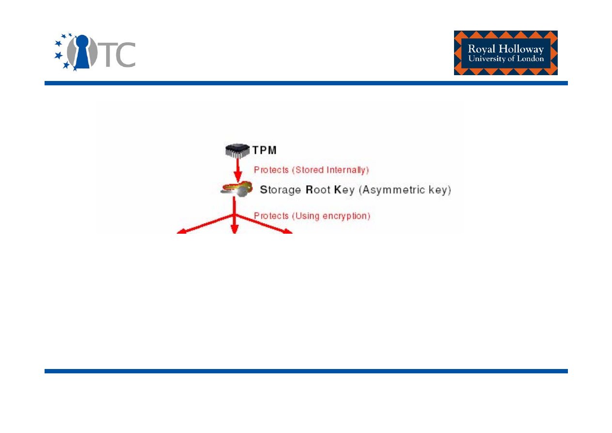
www.opentc.net
26th January 2007
57
Taking ownership of the TPM –
Storage root key (key hierarchy)
Completely separate from the endorsement key pair

www.opentc.net
26th January 2007
58
Activating the TPM
• A deactivated TPM is not able to execute commands
that use TPM resources.
• The difference between a deactivated TPM and a
disabled TPM:
– A deactivated TPM can execute the TPM_TakeOwnership
command (so that the TPM can acquire an owner).
• There are 2 activation flags:
– A non-volatile flag;
– A volatile flag, which takes its state from the non-volatile
flag at start-up.
– When the TPM execution engine checks for TPM activation,
it only checks the volatile flag.

www.opentc.net
26th January 2007
59
Activating the TPM
• The NV flag, pFlags.tpmDeactivated, may be changed
using the TPM_PhysicalSetDeactivated command, which
requires physical presence.
• There is also a TPM_SetTempDeactivated command
which will set the volatile flag, vFlags.tpmDeactivated,
of an activated TPM, to true, i.e. vFlags.tpmDeactivated
= TRUE, thereby deactivating the TPM until it is
rebooted.

www.opentc.net
26th January 2007
60
Activating the TPM
• The TPM may be activated and deactivated without
destroying secrets protected by the TPM.
• When the TPM is deactivated, integrity measurements
are still calculated and stored by the TPM.
• The activate commands are designed for use in
conjunction with the ‘enabling ownership’ command, in
order to prevent rogue software taking ownership of a
platform before the true owner does, and in turn taking
control of all TPM functionality.

www.opentc.net
26th January 2007
61
Activating the TPM
• Sample attack scenario:
– If there was no activation/deactivation functionality:
– If the TPM:
• is enabled; AND
• fFlags.OwnershipEnabled = true.
– Rogue software could then take ownership of TPM and have the
full range of TPM functionality available to it.
• However, when the TPM:
– is enabled;
– fFlags.OwnershipEnabled = true; AND
– permanently deactivated;
• The genuine TPM owner can execute the take ownership
process, and then turn on the remaining TPM functions by
physically activating the TPM.

www.opentc.net
26th January 2007
62
Activating the TPM
• If a remote entity (software) successfully executes the
take ownership command on a deactivated TP before
the legitimate owner, it will gain only restricted access
to TP functionality until the platform is activated.
• As physical presence is required for TPM activation, the
remote software cannot perform this step, and thus the
potential control that rogue software may have over a
hijacked TPM is limited.

www.opentc.net
26th January 2007
63
Open_TC EC Contract No: IST-
027635
The
support for the development of the course material is
provided by the OpenTC project
which is co-financed by the
EC.
If you need further information, please visit our website
www.opentc.net or contact the coordinator:
Technikon Forschungs- und Planungsgesellschaft mbH
Richard-Wagner-Strasse 7, 9500 Villach, AUSTRIA
Tel.
+
43 4242 23355 – 0
Fax.
+
43 4242 23355 – 77
Email coordination@opentc.net
The information in this document is provided “as is”, and no guarantee or
warranty is given that the information is fit for any particular purpose.
The user thereof uses the information at its sole risk and liability.
Trusted Computing IY5608:
The Roots of Trust - The RTM and the
TPM
Eimear Gallery
Royal Holloway, University of London
e.m.gallery@rhul.ac.uk

www.opentc.net
2nd February 2007
2
Clearing the TPM
• In order to clear a TPM, two commands are defined.
– The first is the owner clear command, TPM_OwnerClear, an
‘owner- authorised’ command.
• This command remains available for use by the TPM owner
unless the disable clear function, TPM_DisableOwnerClear, is
executed.
• Once this has been invoked, the only way to clear the TPM is
via physical presence.
– The second command is the force clear command,
TPM_ForceClear, which requires the assertion of physical
presence.
• As above, this command is available unless the owner
executes the disable force clear command,
TPM_DisableForceClear.
• In this instance, however, the force clear command only
remains disabled until the next start-up.

www.opentc.net
2nd February 2007
3
Clearing the TPM
• The clearing of the TPM results in the following actions:
– Invalidation of the SRK;
– Invalidation of the tpmProof;
– Invalidation of the TPM owner authorisation data; and
– A reset of both volatile and non-volatile data to
manufacturer defaults.
• The endorsement key pair, however, is not affected.

www.opentc.net
2nd February 2007
4
TP identities
• The endorsement key is not used to identify a trusted
platform.
• A platform may have multiple TP identities, where a TPM
identity or TP identity is synonymous with an Attestation
Identity Key (
AIK
). Such an identity must be:
– Statistically unique;
– Difficult to forge; and
– Verifiable to a local or remote entity.

www.opentc.net
2nd February 2007
5
TP identities
• An TP identity/attestation identity key:
– Guarantees that certain properties hold for the platform
associated with the identity:
• A TPM uses attestation identities when proving that it is a
genuine TPM (conformant to TCG specifications), without
identifying a particular TPM.
– Allows linkage of behaviour to previous usage of a
platform using that same identity.

www.opentc.net
2nd February 2007
6
Acquiring an AIK credential –
Attestation entities (extended)
• Privacy Certification Authority (Privacy-CA; P-CA) attests
that an ID/AIK belongs to a TP.

www.opentc.net
2nd February 2007
7
Attestation identity keys
• An AIK is a RSA 2048-bit key pair.
• The private key from an AIK pair can be used to digitally sign
data generated by the TPM:
– PCR information;
– Non-migratable keys generated by the TPM.
• The public key from this AIK pair is used to verify digital
signatures generated by the TPM.
• A TPM may have an unlimited number of AIKs.

www.opentc.net
2nd February 2007
8
Generating an AIK
Stage 1:
• A TPM_MakeIdentity command is called on the TPM:
– The properties of the key pair to be generated are specified as input.
– The digest of the ‘identity label’ chosen by the TPM owner and an
identifier for the P-CA chosen to certify the new identity is also input.
• The TPM generates an attestation identity key pair.
• The TPM creates an identity-binding:
– Takes the:
• The public key from the newly generated AIK.
• The digest of the ‘identity label’ chosen by the TPM owner and the identifier for
the P-CA chosen by the owner to attest to the new identity.
– Computes a digital signature (generated using the private AIK) over the
above data.
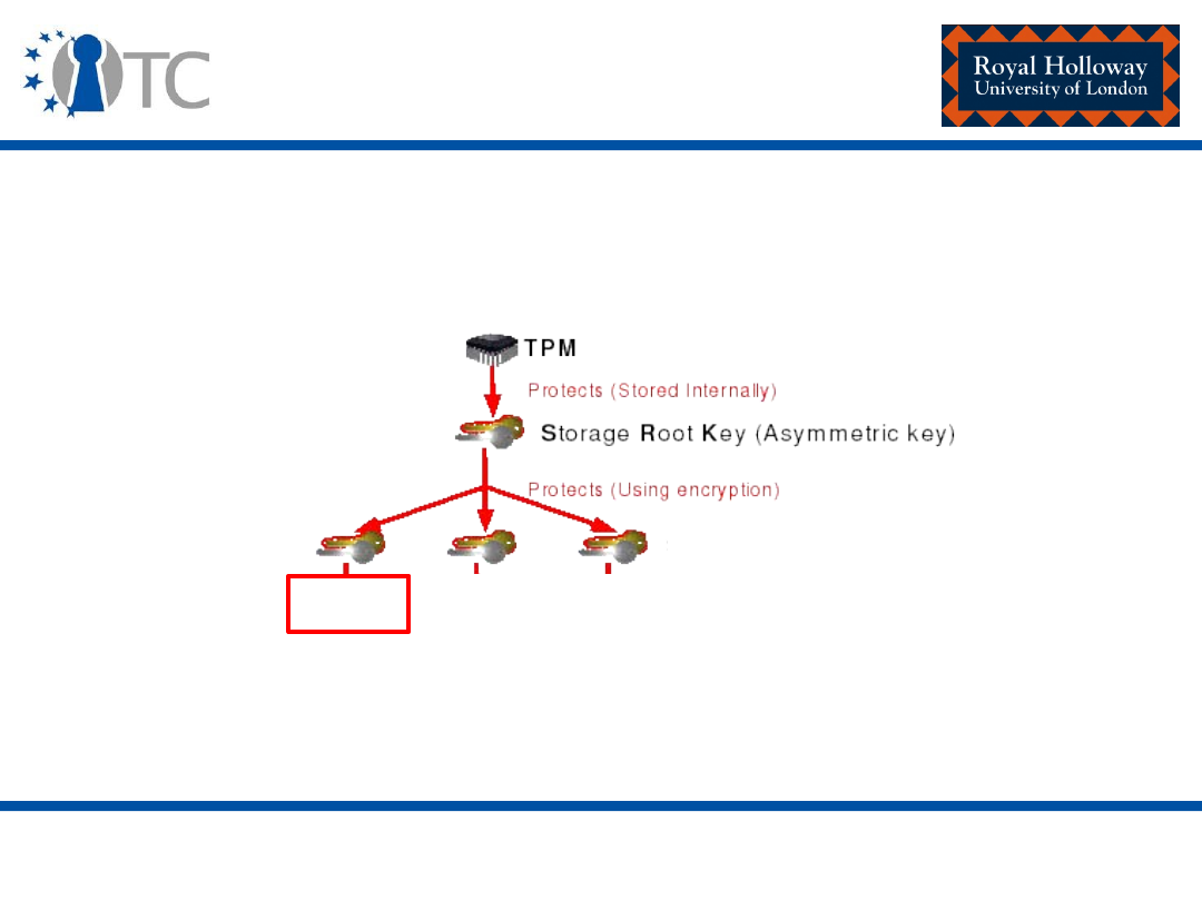
www.opentc.net
2nd February 2007
9
Generating an AIK
AIK

www.opentc.net
2nd February 2007
10
Generating an AIK
Stage 2:
• The TSS_CollateIdentityRequest is called in order to assemble
all data needed by a Privacy-CA. This includes:
– The data linked to the identity-binding (i.e. the public key from
the newly generated AIK, the ‘identity label’, and the identifier
for the P-CA);
– The identity-binding;
– The TP credential set – the endorsement credential, the platform
credential and any conformance credentials.
Stage 3:
• The data described above is encrypted under the public key
of the chosen P-CA and sent to the P-CA.

www.opentc.net
2nd February 2007
11
Generating an AIK
Stage 4:
• The P-CA decrypts the message received.
• The P-CA inspects the credentials and deduces whether the
platform described in them is a genuine TP.
• The P-CA inspects the identity-binding and verifies that it is
consistent with the supplied information:
– It ensures that the message was destined for it (and not another
P-CA);
– It verifies the signature using the public AIK supplied.

www.opentc.net
2nd February 2007
12
Generating an AIK
• The P-CA has no way of knowing, however, that the public AIK
belongs to the genuine TPM described in the credentials.
• So, the P-CA then:
– Generates an attestation identity credential;
– Encrypts it using a symmetric key;
– Encrypts the symmetric key such that it can only be decrypted
by a legitimate TPM.
– The P-CA also sends an encrypted hash of the public-attestation
identity key from the signed identity-binding such that it can only
be decrypted by a legitimate TPM.
[Encryption completed using the public EK in the credentials received.]

www.opentc.net
2nd February 2007
13
Generating an AIK
Stage 5:
• The TPM decrypts the data (excluding the encrypted
attestation identity credential).
• If the data was intended for the TPM – the decrypted data
contains a hash of a public key belonging to an attestation
identity key pair of the TPM.
• If a match is found – the TPM releases the P-CA symmetric
key to the host platform.
• This is all accomplished using the TPM_ActivateIdentity
command.

www.opentc.net
2nd February 2007
14
Generating an AIK
Stage 6:
• Only if stage 4 has been successful will the attestation
identity credential be decrypted using the symmetric key
generated and supplied by the P-CA.
www.opentc.net
2nd February 2007
15
Platform attestation identity
credential
String
"TC PA TPM Identity"
TPM identity chosen name
Platform type + platform security properties
Privacy-C A reference
String
TPM type + TPM security properties
TPM attestation identity public key

www.opentc.net
2nd February 2007
16
Authenticated boot
• The process by which measurements about the
firmware/software state of the platform (integrity
measurements) are reliably
measured
and
stored
(but not
checked).
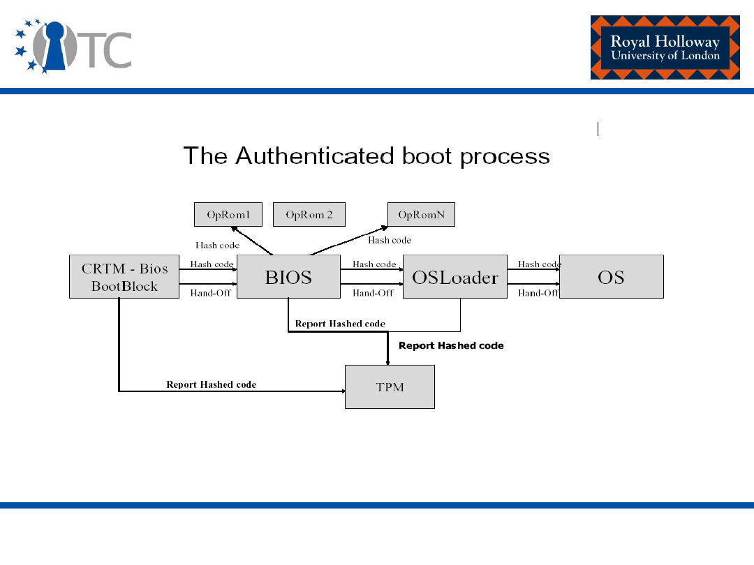
www.opentc.net
2nd February 2007
17
Authenticated boot

www.opentc.net
2nd February 2007
18
Authenticated boot
• Platform configuration registers (PCRs)
– Used to store condensed software integrity measurements
of a platform (called integrity metrics).
– A TP must have a minimum of sixteen PCRs (PCR0 –
PCR15).
– Each storage register has a length equal to the SHA-1
digest: 20 bytes.

www.opentc.net
2nd February 2007
19
Authenticated boot
– Each PCR holds a summary value of all the measurements
presented to it:
• Less expensive than holding all individual measurements in
the TPM.
• This means that an unlimited number of results can be
stored.
• The fewer sequences/PCRs there are, the more difficult it is to
determine the meaning of the sequence.
• The more there are, the more costly it is to store sequences
in the TPM.
– A PCR must be a TPM shielded location, protected from
interference and prying.

www.opentc.net
2nd February 2007
20
Authenticated boot
– A PCR value is defined as:
• SHA-1 (existing PCR value || latest measurement result )
• Two commands which can be called during the
authenticated boot process include:
– TPM_Extend: Incorporates a new integrity measurement
into a PCR.
– TPM_SHA1CompleteExtend: Completes a SHA-1 digest
process on the component to be measured and then
incorporates a new integrity measurement into a PCR.

www.opentc.net
2nd February 2007
21
Authenticated boot
– Values recorded to PCRs cannot be removed or deleted
until a reset.
– Details of the measuring process, namely the measured
value, are recorded to the Stored Measurement Log (SML)
outside the TPM.

www.opentc.net
2nd February 2007
22
Authenticated boot
• Platform specific specifications define the use of PCRs for a
particular platform.
• Example: TCG PC client specific implementation for conventional
BIOS version 1.2.
Option ROM configuration code
3
Option ROM code
2
Host platform configuration
1
CRTM, BIOS, and Host platform extensions
0
PCR Usage
PCR index

www.opentc.net
2nd February 2007
23
Platform attestation
• Attestation identity keys are used to sign integrity
reports (PCR values).
• The recipient can then evaluate:
– How trustworthy
the information is
using the signature
of the platform on the measurements and the platform
identity certificate.
– How trustworthy
the software configuration
of the
platform is using the reported measurements.

www.opentc.net
2nd February 2007
24
Platform attestation–
Attestation entities (extended)
•
A validation entity (VE) certifies integrity measurements, i.e.
measured values and measurement digests, which
correspond to correctly functioning or trustworthy platform
components, for example embedded data or program code, in
the form of validation certificates.
• In order to evaluate how trustworthy
the software
configuration
of the platform is, the reported measurements
are compared against the expected integrity metrics
retrieved from certificates generated by VEs.

www.opentc.net
2nd February 2007
25
Direct anonymous attestation
(DAA)
• P-CA:
– Point of weakness as they are capable of:
• User/TPM activity tracking; and/or of
• Making unwanted disclosures of platform information.
• DAA removes the necessity to disclose the public value of the
endorsement key to a P-CA
• DAA is based on a family of cryptographic techniques known as zero
knowledge proofs.
• DAA allows a TPM to convince a remote ‘verifier’ that it is indeed
valid without the disclosure of the TPM public endorsement key,
thereby removing the threat of a TTP collating data which may
jeopardize the privacy of the TPM use.

www.opentc.net
2nd February 2007
26
Secure boot – potential (1)
• A DIR (Data Integrity Register) is a version 1.1
component.
• A DIR is defined as a 20-byte non-volatile register.
• Version 1.2 - DIR is deprecated.
• The TPM must still support the functionality of the DIR
register in the NV storage area.

www.opentc.net
2nd February 2007
27
Secure boot – potential (2)
Proposed solutions
• If the TPM has the same number of DIRs as PCRs.
• The expected PCR values are written by the TPM owner
to the DIRs.
• The CRTM and the measurement agents measure the
software components on the platform.
• Every time a final PCR value is computed, the PCR value
is compared to the corresponding DIR value.
• If the two values match, control is passed to the next
software component and the boot process continues;
otherwise an exception is called and the boot process
halted.

www.opentc.net
2nd February 2007
28
Secure boot – potential (3)
Proposed solutions
• Alternatively, all expected PCR values could be held in
unprotected memory and their summary or a
cumulative digest held in a lone DIR.
• When a PCR value has been calculated, the RTM or
measurement agent checks that:
– The calculated PCR value matches its expected value in
the table; and
– The cumulative digest of the expected table of PCR values
matches that held in the DIR.

www.opentc.net
2nd February 2007
29
Protected storage
• The protected storage mechanism on a TPM enables:
– The generation and protection of asymmetric key pairs;
– Keys and data to be encrypted such that they can only be
decrypted by a particular TPM;
– Keys and data to be encrypted such that they can only be
decrypted by a particular TPM when the software configuration of
the host platform is in a specified state.
(this is generically called “sealing”, where data/keys are sealed
to the integrity metrics which reflect the software configuration
of host on which data can be unsealed/keys can be used).
• The TPM is not a generic bulk encryption device – Symmetric
encryption is not exposed for general message encryption.
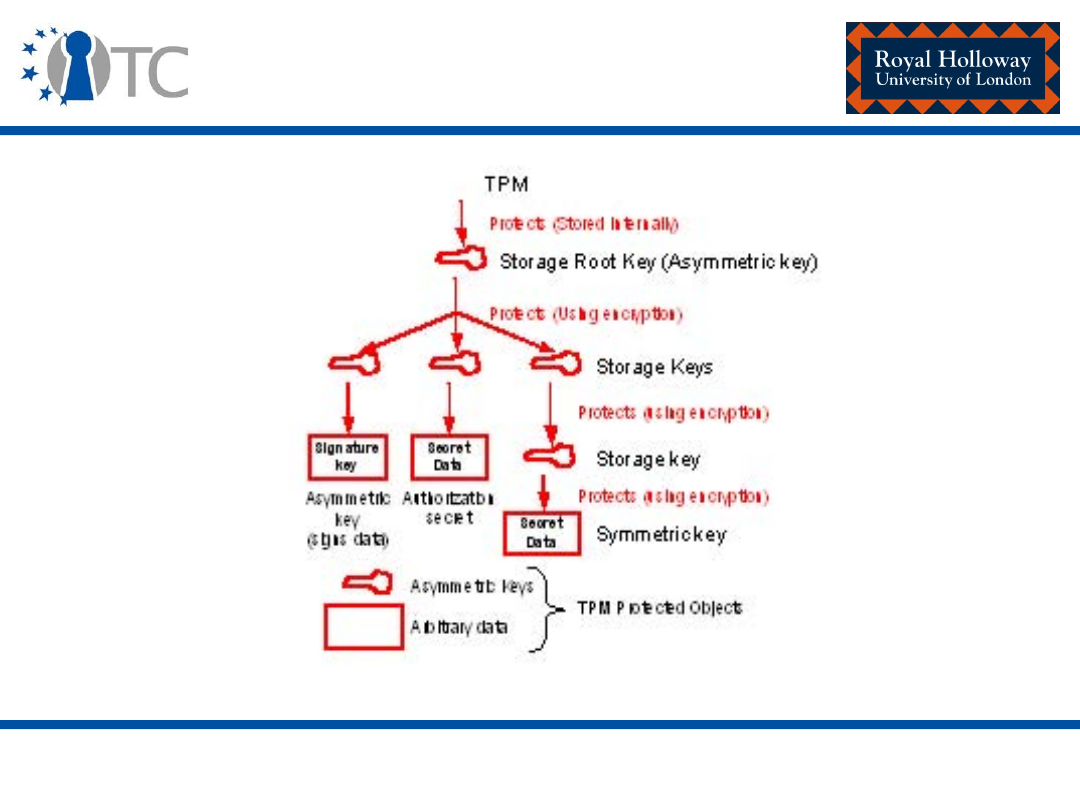
www.opentc.net
2nd February 2007
30
Protected storage object
hierarchy

www.opentc.net
2nd February 2007
31
Migratable and non-migratable
objects
• Non-migratable objects (keys):
– Locked to an individual TPM;
– Never duplicated;
– The private keys from non-migratable key pairs are never
available in plaintext outside of the TPM;
– Non-migratable key pairs must be created inside the TPM.
• The TPM never creates any arbitrary data – in this way,
arbitrary data is always generated outside the TPM and
may be duplicated ad infinitum by its owner.
• In the strictest sense – TPM data objects are always
migratable.

www.opentc.net
2nd February 2007
32
Migratable and non-migratable
objects
• Migratable objects:
– Can be created outside the TPM and protected by the TPM,
or created inside by TPM;
– Can be replicated ad infinitum by its owner;
– The extent of duplication of migratable keys is known only
to the owner of that key.
• The essential architectural difference between
migratable and non-migratable TPM keys is the source
of their migration authorisation data:
– The migration authorisation data for non-migratable keys
is known only to the TPM – tpmProof;
– The owner of a migratable key creates the migration
authorisation data.
www.opentc.net
2nd February 2007
33
Creating keys
R NG
asymmetric key generation
structure generation
TPM _C reateWrapKey
parentHandle
dataUsageAuth
dataM igrationAuth
keyInfo
parentKey.usageAuth
wrappedKey -
Public parameters (plain text)
Private parameters (encrypted)

www.opentc.net
2nd February 2007
34
Creating keys
• Authorisation values (optional):
– dataUsageAuth : encrypted usage authorisation for the key created
– dataMigrationAuth : encrypted migration authorisation for the key
created
• keyInfo and wrappedKey – TPM_key type:
– version
– keyUsage : operations permitted with the key
– keyFlags : migration
– authDataUsage : conditions when it is required that authorisation
be presented
– algorithmParams : information regarding the algorithms for this key
– PCRInfoSize
– PCRInfo : pcrSelection,
digestAtCreation
, digestAtRelease
– pubKey
– encDataSize
– encData : E
K
(authValues, pubDataDigest (integrity check), privKey)

www.opentc.net
2nd February 2007
35
TPM_LoadKey2
• This capability is used to load a (plaintext) public and a
(ciphertext) private TPM key into the TPM.
• Must be used before a key can be used to seal, unseal,
unbind, sign or perform any other such action.
• This command will fail if:
– The version of the wrapped key is not the current TPM
version;
– There is an integrity check fail;
– digestAtRelease for the parent TPM key does not match
the current PCRs;
– The key is non-migratable but was not generated on this
platform (the tpmProof value doesn’t match).

www.opentc.net
2nd February 2007
36
TPM keys
• Note the difference:
– When you are loading a key, you must demonstrate
knowledge of the AuthData for the parent key and match
the DigestAtRelease associated with the parent key.
– When you are using a key, you must demonstrate
knowledge of AuthData for the key and match the
DigestAtRelease associated with the key.

www.opentc.net
2nd February 2007
37
Key types
• Storage keys
– Used by TCG-aware applications;
– Used to encrypt other keys and arbitrary data;
– Storage keys must be as strong as 2048-bit RSA;
– Keys may be migratable or non-migratable.
• Signature keys
– Used by TCG-aware applications;
– Used to sign arbitrary data;
– Keys may be migratable or non-migratable.

www.opentc.net
2nd February 2007
38
Key types
• Attestation identity keys
– Non-migratable signing keys;
– Exclusively used to sign data originated from the TPM (PCR
data, non-migratable TPM keys).
• Bind keys
– Used to encrypt data on one platform for decryption on
another (within the TPM).
• Legacy keys
– Created outside the TPM.
– They can be imported to the TPM after which they may be
used for signing and encryption operations.
www.opentc.net
2nd February 2007
39
TPM_Seal
TPM_Seal states the password and PCR values that must be used
to recover the data with TPM_Unseal
keyHandle
encAuth
pcrInfo (pcrSelection, digestAtRelease)
inData
key.usageAuth
sealedData (includes
–pcrInfo:
pcrSelection,
digestAtCreation,
digestAtRelease;
and encData)
input
output

www.opentc.net
2nd February 2007
40
TPM_Seal
• pcrInfo:
– pcrSelection – the selection of PCRs to which the data is
bound.
– digestAtCreation – the digest of the PCR indices and PCR
values to verify when revealing Sealed Data that was
associated with PCRs and encrypted.
– digestAtRelease – the composite digest value of the PCR
values, at the time when the sealing is performed.
• encData:
– E
K
(authData, tmpProof, digest of pcrInfo, data)

www.opentc.net
2nd February 2007
41
TPM_Seal
• The application which calls the TPM_Seal or management
software on the platform:
– Collects a list of the current PCR values from the TPM (ones
used to create digestAtCreation); and
– Stores this list and a list of the selected target PCRs with the
TPM protected object.
www.opentc.net
2nd February 2007
42
TPM_Unseal
TPM _Unseal
keyHandle
dataAuth (sealed data)
BLOB (the encrypted data
generated by TPM _S eal)
key.usageAuth
C heck that the value
of the
digestAtRelease
associated with the
sealed blob
matches
the digest of the
PCR indices and
current
PCR values
.
C heck that the
required
authorisation values
are know to the
caller.
data
digestAtC reation

www.opentc.net
2nd February 2007
43
TPM_Unseal
• When the unsealed data has been returned by the TPM,
the management software can verify the software state
of the platform when the TPM object was created.
• The management software:
– Collects the record of the software state at creation
(digestAtCreation from the TPM object) and the list of PCR
indices and PCR values associated with the TPM object.
– Computes a digest over the list of PCR indices and PCR
values.

www.opentc.net
2nd February 2007
44
TPM_Unseal
– Compares the digest computed to the digestAtCreation.
– If they are the same the PCR values accurately represents
the record of the software state when the object was
created – otherwise it does not.
• This allows management software to ensure that an
object was created in the correct software environment
– else rogue software may have created the protected
object.
www.opentc.net
2nd February 2007
45
TPM_Unbind
TPM_UnBind – Used for decrypting data which has been
encrypted externally to the TPM using a bind key.
keyHandle
key.usageAuth
BLOB
data

www.opentc.net
2nd February 2007
46
Security services
• Confidentiality – asymmetric encryption.
• Integrity – the 20-bytes of authorisation data associated
with a protected TPM object provides implicit integrity
protection.
• Access control:
– 20-bytes of authorisation data may be associated with a
TPM protected object;
– PCR data.
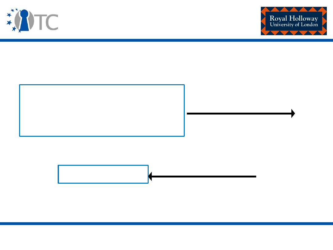
www.opentc.net
2nd February 2007
47
Signing data
TPM_sign – signs data and returns a digital signature.
keyHandle (type,
signature scheme
)
key.usageAuth
Data
signature value

www.opentc.net
2nd February 2007
48
TPM_CertifyKey
• TPM_CertifyKey – allows one key to certify the public portion
of another key.
• A TPM attestation identity key may be used to certify non-
migratable keys but is not permitted to certify migratable
keys.
• This enables a TPM to attest that a key was created on a TPM,
will never be revealed outside of the TPM, and can only be
used under certain conditions (given the host platform is in a
specified software state).

www.opentc.net
2nd February 2007
49
TPM_CertifyKey
• Signing and legacy keys may be used to certify both
migratable and non-migratable keys.
• The usefulness of such a certificate depends on the trust the
recipient has in the certifying key.
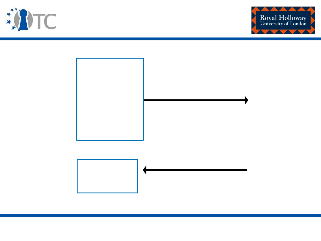
www.opentc.net
2nd February 2007
50
TPM_CertifyKey
certHandle
keyHandle
antiReplay
cert.usageAuth
key.
usageAuth
certifyInfo
outData

www.opentc.net
2nd February 2007
51
TPM_CertifyKey
• certifyInfo:
– version
– keyUsage
– keyFlags
– authDataUsage
– algorithmsParams
– pubKeyDigest
– data: anti replay nonce
– parentPCRStatus : indicate if the parent key was wrapped to
PCRs
– PCRInfoSize
– PCRInfo
• outData: a signature generated on certifyInfo

www.opentc.net
2nd February 2007
52
Authorisation
• Required in order to:
– Authenticate the owner of the TPM.
– Authorise the use of/access to a TPM protected object.
– Authorise migration of a migratable TPM key.
– Authorise the use of a TPM capability.
• Two methods:
– Physical presence;
– Authorisation data.

www.opentc.net
2nd February 2007
53
Physical presence
• Physical presence implies direct interaction by a person with
the trusted platform/TPM.
• The actual implementation is decided by the TPM and
platform manufacturers.
– (the strength of the protection mechanism is determined by an
evaluation of the platform)
• Guiding principle for designers – the protection mechanism
should be difficult or impossible to spoof by rogue software.
• Example – hardware switch (very difficult to circumvent by
rogue software or remote attackers).

www.opentc.net
2nd February 2007
54
Physical presence
• The physical presence indication is implemented as a flag in
volatile memory – PhysicalPresenceV flag.
• When it is set to TRUE – commands which can function
include:
– TPM_PhysicalEnable
– TPM_PhysicalDisable
– TPM_PhysicalSetDeactivated
– TPM_ForceClear
– TPM_SetOwnerInstall
• Precautions must be taken by designers to ensure this flag is
not maskable (dedicated bus cycle could be used).

www.opentc.net
2nd February 2007
55
Authorisation data
• Authorisation data
– Length: 20 bytes.
– For example, a hashed password, or 20 bytes from a
smartcard, may be used.
• Sample types:
– TPM owner authorisation data – owner authorised
commands;
– Protected object authorisation data;
– Key migration authorisation data.

www.opentc.net
2nd February 2007
56
Authorisation data
• The TPM neither knows or cares about the content of an
authorisation value:
– Each individual authorisation value may be unique or may be the
same as another value.
• The TPM is designed, however, to conceal and protect
authorisation values at all stages, i.e.:
– During initial entry of an authorisation value;
– When proving knowledge of a specific authorisation value;
– When changing an authorisation value.

www.opentc.net
2nd February 2007
57
Authorisation data
• There are two protocols which can be used by a
requester to prove that they have knowledge of a
particular authorisation value.
• They have been designed in order to protect against:
– Man in the middle attacks;
– Replay; and
– The exposure of the authorisation data.
• Object independent authorisation protocol (OIAP)
• Object specific authorisation protocol (OSAP)

www.opentc.net
2nd February 2007
58
Object independent authorisation
protocol (
OIAP)
• Used by a requester to prove that it has knowledge of a
particular authorisation value.
• Based upon a “rolling nonce” paradigm:
– This requires that a nonce is sent from one side and
returned in the reply.
– Designed to prevent replay attacks and man-in-the-middle
attack.

www.opentc.net
2nd February 2007
59
Object independent authorisation
protocol (
OIAP)
• Example:
– Assume a TPM command that uses key1;
– The user must know the AuthData for key1 in order to use
the command;
– Assume the caller does not need to authorise the use of
key1 for more than one command.
www.opentc.net
2nd February 2007
60
OIAP
Caller
TPM
TPM_OIAP
nonce1
command ordinal command
║
input
║
nonce2 inAuth
║
return code
║
command output
║
nonce3 resAuth
║
Generate
nonce1
Generate nonce2.
Compute inAuth:
HMAC (key1.usageAuth,
digest of
command input,
nonce1, nonce 2).
Verify inAuth.
Execute the command.
Compute resAuth
HMAC (key1.usageAuth,
digest of command
output, nonce3, nonce2).
Verify
resAuth

www.opentc.net
2nd February 2007
61
OIAP
• Once an OIAP session has been established, its nonces
can be used to authorise the use of any object managed
by the TPM.
• The session can live indefinitely until either party
requests a session termination.
• This is the preferred protocol as it allows usage of the
same session to provide authorisation for different
objects.

www.opentc.net
2nd February 2007
62
Object specific authorisation
protocol (
OSAP)
• Also may be used by a requester to prove that they have
knowledge of a particular authorisation value.
• This is also based upon the “rolling nonce” paradigm.
• Using OSAP, a distinct session needs to be set up for each
object that requires authorisation.
• However, it enables a caller to authorise the use of a
particular object multiple times without having to input the
AuthData more than once.
• This protocol is required in order to set or reset AuthData.

www.opentc.net
2nd February 2007
63
Object specific authorisation
protocol (
OSAP)
• Example:
– Assume a TPM command that uses key1;
– The user must know the AuthData for key1 in order to use
this command;
– Assume the caller needs to authorise the use of key1
multiple times but does not wish to input the AuthData
more than once.
www.opentc.net
2nd February 2007
64
OSAP
Caller
TPM
TPM_OSAP OSAPnonce1
║
nonce1 OSAPnonce2
║
command ordinal
║
command input
║
nonce2 inAuth
║
Generate:
OSAPnonce2 and
nonce 1.
Compute sharedSecret:
HMAC (key1.usageAuth,
OSAPnonce2, OSAPnonce1).
Generate nonce2.
Compute sharedSecret:
HMAC (key1.usageAuth,
OSAPnonce2, OSAPnonce1).
Compute inAuth:
HMAC (sharedSecret,
digest of command input,
nonce1, nonce 2).
Generate
OSAPnonce1.

www.opentc.net
2nd February 2007
65
OSAP
Caller
TPM
return code command output
║
║
nonce3 resAuth
║
Verify resAuth
Verify inAuth.
Execute the
command.
Generate nonce3.
Compute resAuth
HMAC
(sharedSecret,
digest of command
output,
nonce3, nonce 2).

www.opentc.net
2nd February 2007
66
OSAP
• If the TPM user wishes to send another command using the
same session (i.e. another command on the same object) the
session may be kept open.

www.opentc.net
2nd February 2007
67
Authorisation data insertion
protocol (ADIP)
• This protocol is used when a caller wishes to associate AuthData with
a new object.
• When the creation process is started – OSAP is used.
• The caller and the TPM generate a shared secret by calculating the
HMAC of the parent.Auth and the nonces exchanged during the
OSAP protocol.
• This shared secret and a nonce generated by the TPM are then used
by the caller and the TPM as input to the SHA-1 hash function to
generate an ephemeral secret (the hash function output).
• This ephemeral secret is then XORed with the new authorisation
data in order to protect it during insertion into the TPM.

www.opentc.net
2nd February 2007
68
AuthData change protocol
(ADCP)
• The ADCP allows an object owner to change that object’s
AuthData.
• An OSAP session must first be used to authorise use of the
parent object.
• This OSAP session also provides the data required to generate
an ephemeral secret which can then be used to encrypt the
new AuthData, as described in ADIP.
• An OIAP or an OSAP session must also be established in order
to authorise access to the object whose authorisation data is
being changed.

www.opentc.net
2nd February 2007
69
ADCP
• Note – If the authorisation data of the parent object is known
to an entity, they can snoop/eavesdrop on an AuthData
change protocol for a child of that entity and learn the newly
chosen child AuthData.
• Example: If SRKAuth is a known to userA and userB, userA
can snoop on userB while userB is changing the AuthData for
a child of the SRK and deduce the child’s new AuthData.
• In order to prevent this, it is advised that ADCP is used inside
a transport session (described later).

www.opentc.net
2nd February 2007
70
The information in this document is provided “as is”, and no guarantee or
warranty is given that the information is fit for any particular purpose.
The user thereof uses the information at its sole risk and liability.
The
support for the development of the course material is provided
by the OpenTC project
which is co-financed by the EC.
If you need further information, please visit our website
www.opentc.net or contact the coordinator:
Technikon Forschungs- und Planungsgesellschaft mbH
Richard-Wagner-Strasse 7, 9500 Villach, AUSTRIA
Tel.
+
43 4242 23355 – 0
Fax.
+
43 4242 23355 – 77
Email coordination@opentc.net
Open_TC EC Contract No: IST-
027635

Trusted Computing IY5608:
The RTM and the TPM
Infrastructure Working Group Activity
Eimear Gallery
Royal Holloway, University of London
e.m.gallery@rhul.ac.uk

www.opentc.net
16
th
February 2007
2
Migratable and non-migratable
keys
• Non-migratable keys:
– Locked to an individual TPM;
– Never duplicated;
– The private keys from non-migratable key pairs are never
available in plaintext outside of the TPM;
– Non-migratable key pairs must be created inside the TPM.
• Migratable keys:
– Can be created outside the TPM and protected by the TPM,
or created inside by TPM;
– Can be replicated ad infinitum by its owner;
– The extent of duplication of migratable keys is known only
to the owner of that key.

www.opentc.net
16
th
February 2007
3
Migratable and non-migratable
keys
• The essential architectural difference between
migratable and non-migratable TPM keys is the source
of their migration authorisation data:
– The migration authorisation data for non-migratable keys
is known only to the TPM – tpmProof.
– The owner of a migratable key creates the migration
authorisation data.

www.opentc.net
16
th
February 2007
4
Key migration
• There are two methods by which a migratable key can
be migrated.
1. Immediate migration (rewrap) – a direct copying
mechanism.
2. Migration via an intermediary (migrate) – uses an
intermediary in the migration process.
•
Neither
method
:
– Implicitly ensures that a migratable TPM key object is
copied to a TP.
– Restricts the number of duplicate copies of any given TPM
migratable key object.

www.opentc.net
16
th
February 2007
5
Key migration initiation –
‘rewrap’ and ‘migrate’
• The TPM owner authorises a particular migration
destination, i.e.
– the use of a particular destination public key in the case of
‘rewrap’; or
– the use of a particular intermediary public key in the case
of ‘migrate’.
• The usage authorisation data of the parent key currently
wrapping the key-to-be-migrated is submitted (so that
the key-to-be-migrated can be decrypted).
• The migration authorisation data required for the key-to-
be-migrated is submitted.

www.opentc.net
16
th
February 2007
6
Key migration - rewrap
• Following the input of the required authorisation data:
– The source TPM encrypts the private key-to-be-migrated
using the destination platform’s public key.
• This is then forwarded to the destination platform in
conjunction with a plaintext object describing the public
key from the key pair being migrated.

www.opentc.net
16
th
February 2007
7
Key migration - migrate
• The alternate migration method (migrate) involves the
use of an intermediary.
• In this instance, the private key-to-be-migrated is
encoded using optimal asymmetric encryption padding
(OAEP) and XORed with a one-time pad.
• The resultant data is then encrypted under the public
key of the intermediary.

www.opentc.net
16
th
February 2007
8
Key migration - migrate
• The intermediary unwraps the key and rewraps it under
the public key of the destination platform.
• The XOR encryption prevents the intermediary gaining
unauthorised access to the migrated key.
• The one-time pad must, however, be made available to
the destination platform so that the migrated key can
eventually be integrated into the protected storage
hierarchy of the destination platform.

www.opentc.net
16
th
February 2007
9
Key migration - rewrap and
migrate
• While the TPM will check that a particular destination or
intermediary public key is at least as strong as 2048-bit
RSA, it is up to the TPM owner to ensure that the public
key does actually represent the desired destination TPM
or intermediary.
• A migratory key can essentially be sent to any arbitrary
platform, not necessarily a trusted platform.

www.opentc.net
16
th
February 2007
10
Certifiable migratable keys
• In version 1.1 specifications, there were two key types
migratable and non-migratable keys.
• The TPM could only certify non-migratable keys.
• Need for a key that allows migration but also allows for
certification – “certifiable migratable keys - CMK”.

www.opentc.net
16
th
February 2007
11
Certifiable migratable keys
• Certifiable migratable keys are keys which are created
on a TPM and which may be migrated but only under
strict controls.
• The destination of the key must be authorised by the
TPM owner and a migration selection authority.

www.opentc.net
16
th
February 2007
12
Transport protection
• Facilitates the establishment of a secure channel
between a TPM and a secure process.
• The secure channel provides confidentiality and integrity
protection of commands (command input and output)
sent to/from the TPM.
• Its also provides a logging function so that all commands
sent to the TPM during a transport session can be
recorded.

www.opentc.net
16
th
February 2007
13
Transport protection – session
establishment
• Generation of 20 bytes of transport authorisation data
between the caller and the TPM.
• 2 purposes:
– Used as input when generating the encryption key for use
between the TPM and the caller to provide command
confidentiality.
– It is also used as the HMAC key when sending the
TPM_ExecuteTransport command so that the command
can be authorised.
• Generated:
– By the caller; and
– Encrypted under a public key whose corresponding private
key is available to the TPM.
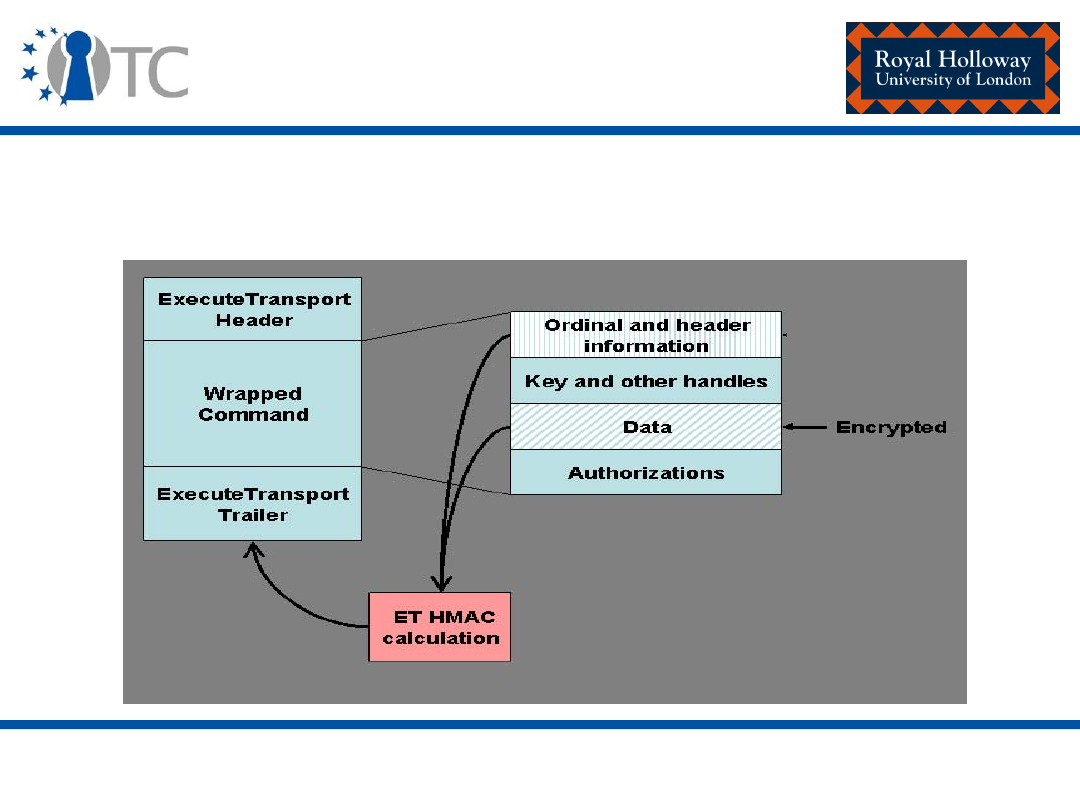
www.opentc.net
16
th
February 2007
14
Transport protection
• Once a session has been established:
TPM_ExecuteTransport can be called.

www.opentc.net
16
th
February 2007
15
Transport protection –
encryption and authorisation
• Authorisation
– Of TPM_ExecuteTransport is provided by the calculation of
the HMAC on a subset of elements from the wrapped
command – the command ordinal, header information and
data fields.
– The HMAC key is the transport authorisation data
established during session establishment.
• Integrity
– Of data transmitted inside the transport session is
provided by the HMAC.

www.opentc.net
16
th
February 2007
16
Transport protection –
encryption and authorisation
• Confidentiality
– Of data transmitted inside the transport session is
provided using encryption of the command to be protected
or, more specifically, the input and output parameters of
the command to be protected.
– XOR is generally used as the encryption algorithm.
– The TPM can optionally implement alternate algorithms for
the encryption of commands sent to the
TPM_ExecuteTransport command.

www.opentc.net
16
th
February 2007
17
Transport protection – logging
and exclusive transport sessions
• A session log provides a log of each command used
during a particular session.
• It is also possible for a caller to establish an exclusive
transport session with a TPM.
– An exclusive transport session is one which is terminated if
any command outside the established session is called.
– Only one exclusive session may be supported at one time.

www.opentc.net
16
th
February 2007
18
Delegation
• Prior to the version 1.2 specification set, the set of “TPM
owner authorised” commands could only be executed if
knowledge of the TPM owner authorisation data was
demonstrated.
• Therefore, the TPM owner was required every time one
such command needed to be called.
• Alternatively, the 20 bytes of owner authorisation data
could be forwarded to another entity such that the
required “owner authorised” command could be
executed.

www.opentc.net
16
th
February 2007
19
Delegation
• This could potentially leave the platform open to attack.
• In order to resolve this issue, a delegation model is
included in the version 1.2 specifications.
• This enables a TPM owner to delegate privileges to
individual entities and/or trusted processes.
• In order to implement this mechanism, two tables are
required:
– A family table; and
– A delegation table.

www.opentc.net
16
th
February 2007
20
Delegation – the delegation table
• Must have a minimum of two rows (however, the TPM
facilitates caching of rows outside the TPM).
• A delegation table entry contains:
– A list of command ordinals for use by the delegate;
– The identity of a process that can use the commands
reflected in the command ordinal list (PCR information –
selection and value definition); and/or
– The AuthData value required in order to use the
commands reflected in the command ordinal list.
– Each entry is also assigned a family name, identifying the
family to which the delegation belongs.

www.opentc.net
16
th
February 2007
21
Delegation – the family table
• Must have a minimum of eight rows.
• The family table:
– Provides a method for grouping delegations.
– Provides validation and revocation of ‘delegation table’
rows exported from the TPM.
– Enables the validation of all delegations in a family (by a
TTP).

www.opentc.net
16
th
February 2007
22
Locality
• The concept of locality permits trusted processes
communicating with the TPM to indicate from where the
command has originated.
• In order to implement this, a modifier is sent in
conjunction with the TPM command.
• The TPM cannot, however, validate the modifier
received.
• The TPM is currently required to understand four
modifiers.

www.opentc.net
16
th
February 2007
23
Locality
• Designed for use in conjunction with isolation
technologies.
• Locality may be used in conjunction with PCR definition
and use.
• It enables the definition of PCRs which may be:
– Reset at times other than TPM start-up, e.g. partition start-
up, by processes executing in particular localities; and/or
– Extended only by processes executing in particular
localities.
(See platform specific specification – e.g. TCG PC client
specific implementation for conventional BIOS version 1.2)

www.opentc.net
16
th
February 2007
24
Locality
• For example TCG PC client specific implementation for
conventional BIOS version 1.2:
– Locality 4 modifier indicates that a command was
generated by the D-RTM.
– PCR 17 can only be extended by processes (the D-RTM)
executing in locality 4.
– It is also defined that PCR 17-20 can be reset by processes
(the D-RTM) running in locality 4.

www.opentc.net
16
th
February 2007
25
Time-stamping
• Provides proof of a time interval not a time instance:
– The ‘time-stamp’ provided is a representation of the
number of ticks a TPM has counted.
• The specification makes no requirement on the
mechanism required to implement the tick counter on
the TPM.
• It is the responsibility of the caller to associate the ticks
to the actual co-ordinated universal time (UTC).

www.opentc.net
16
th
February 2007
26
Time-stamping
• A sample protocol is specified in the specification
demonstrating how this may be achieved.
• Use of the specified protocol is not required.
• The availability of timing ticks and tick resolution is an
area of differentiation available to TPM manufacturers
and platform providers.

www.opentc.net
16
th
February 2007
27
Audit and maintenance
• Audit and maintenance mechanisms are optional.
• If audit functionality is implemented, the mechanism
must be comprised of pre-defined set of components.
• Maintenance is vendor-specific but if maintenance
mechanisms are implemented, a set of minimum
security requirements must be met.
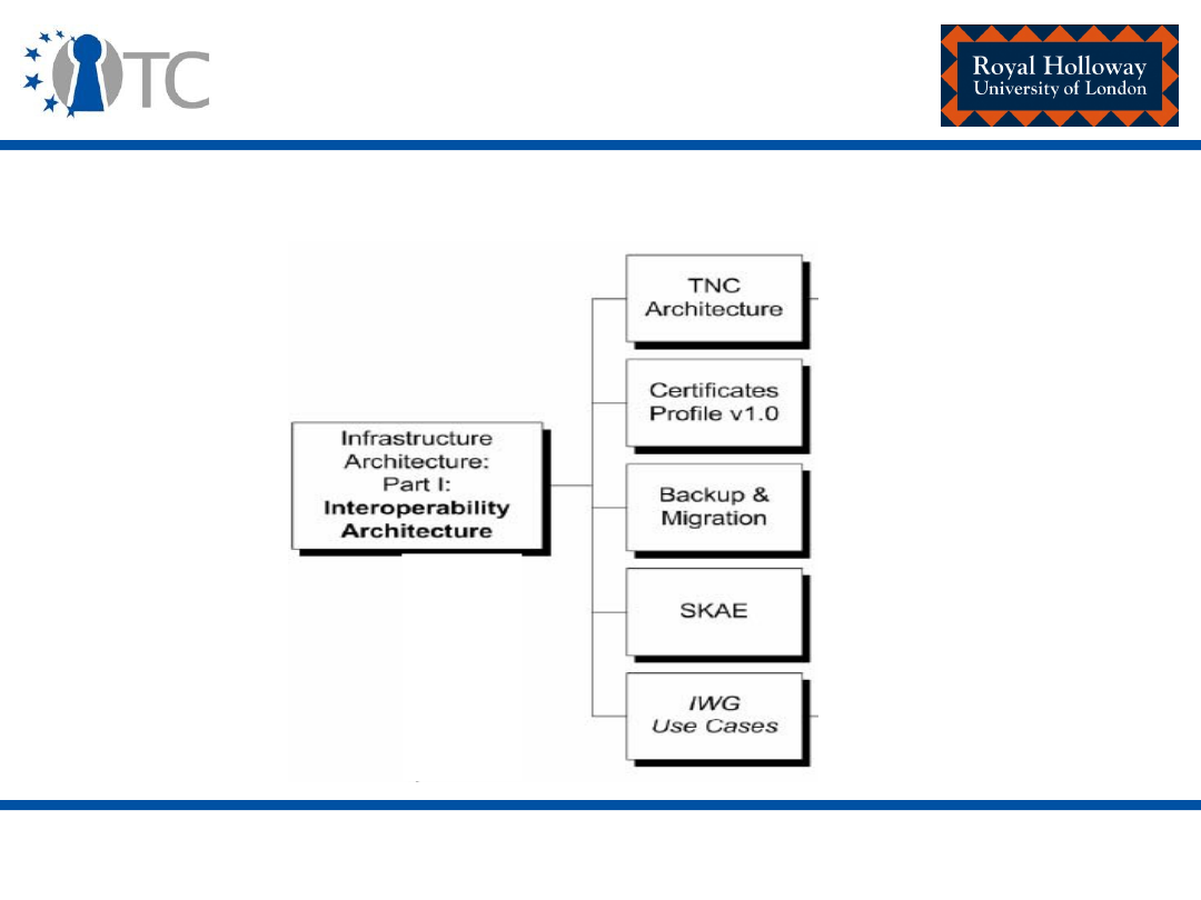
www.opentc.net
16
th
February 2007
28
Infrastructure working group
(IWG)
• Concerned with interoperability among systems containing TCG
technology.
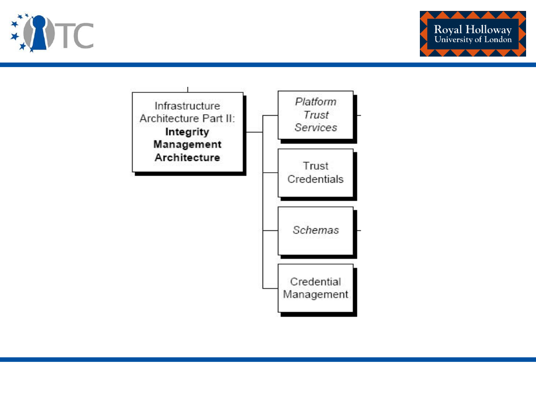
www.opentc.net
16
th
February 2007
29
Infrastructure working group
(IWG)
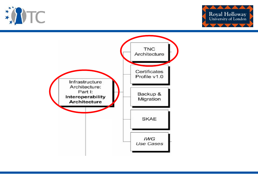
www.opentc.net
16
th
February 2007
30
Infrastructure working group
(IWG) – Our focus

www.opentc.net
16
th
February 2007
31
Reference architecture for
interoperability
• The TP platform lifecycle
• The TP deployment architecture
• Entities, assertions and signed structures
• Types of credentials in the TP lifecycle
• Privacy issues
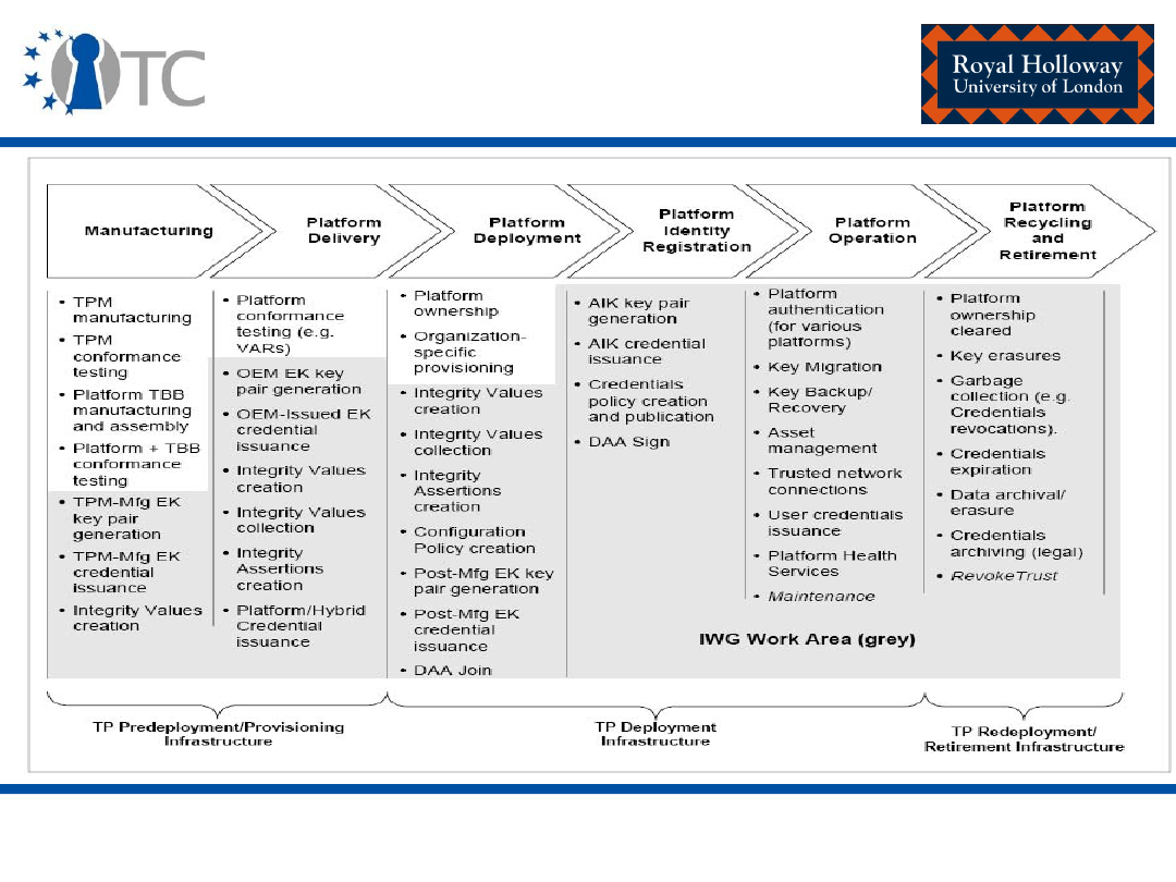
www.opentc.net
16
th
February 2007
32
IWG – The TP lifecycle

www.opentc.net
16
th
February 2007
33
IWG – The TP lifecycle
• TP pre-deployment/provisioning infrastructure
– Set of entities and functions that support the preparation of TPs
before they are deployed.
• E.g. entities supporting EK credential creation or performing
conformance-related functions (e.g. TPM manufacturers, conformance
labs).
• TP deployment infrastructure
– Set of entities that support TP use outside the manufacturing
control boundary.
• E.g. AIK-credential issuing authorities (P-CAs).
• TP redeployment/retirement infrastructure
– Set of entities and functions that support the retirement/ de-
provisioning of existing TPs (in the case of old TPs) and the re-
deployment of existing TPs with new credentials, possibly new
ownership.

www.opentc.net
16
th
February 2007
34
TP lifecycle - Manufacturing
• Integrity values creation:
– Information regarding a given TPM, TBB components, firmware, software
and trusted platform configuration must be collected.
– Generated in this phase by the manufacturers of each component.
– Consumed by conformance laboratories who verify the correctness of the
implementation of a given component.
• TPM-manufacturer EK key pair generation:
– TPM manufacturer is expected to make the EK key pair physically present
inside a TPM.
– Can be generated off-chip and inserted into the TPM, OR can be
generated on-chip.
– Referred to as early EK generation – normative behaviour.

www.opentc.net
16
th
February 2007
35
TP lifecycle - Manufacturing
• TPM-manufacturer EK-credential issuance:
– TPM manufacturer is expected to issue an EK-credential during this
phase.
– Referred to as early EK-credential issuance – normative behaviour.
• TPM-manufacturer DAA-credential issuance:
– A TPM manufacturer could issue a DAA credential by executing the DAA-
Join protocol.

www.opentc.net
16
th
February 2007
36
TP lifecycle – Platform delivery
• Integrity values creation:
– OEM generates integrity values pertaining to the platform, the TBB
components, firmware and software that make-up the platform.
• Integrity values collection:
– Collection of integrity values generated by component manufacturers for
consumption by conformance evaluation entity.

www.opentc.net
16
th
February 2007
37
TP lifecycle – Platform delivery
• Integrity assertions creation:
– Conformance evaluation entities publish their positive findings regarding
the evaluation of a given TPM, TBB component and platform in the form
of digitally signed integrity assertions.
• OEM EK key pair generation:
– EK key pair generation (on the TPM) can occur in this phase, prior to the
platform being taken over by its owner.
– Referred to as early EK generation – non-normative behaviour.
• OEM EK-credential issuance:
– EK-credentials can be issued by an entity that is in an authoritative
position to make assertions about the validity of an EK key pair.
– Referred to as early EK-credential issuance – non-normative behaviour.

www.opentc.net
16
th
February 2007
38
TP lifecycle – Platform
deployment
• Integrity assertions collection:
– Owner of the platform needs to collect the integrity assertions regarding
components of the platform from the entities that produced and/or tested
those components.
• Post-manufacturing EK Key pair generation:
– EK key generation can occur in the platform deployment phase.
– It is the platform owner that performs key pair generation operations at
this stage.
– Referred to as late EK generation.
• Post-manufacturing EK credentials issuance:
– The platform owner makes the decision as to who issues the credential.
– Credential issuance could be done by the owner or by some entity trusted
by the owner.
– Referred to as late EK-credential issuance.

www.opentc.net
16
th
February 2007
39
TP lifecycle – Platform
deployment
• Platform credentials issuance:
– Issuance of the platform endorsement credential, which attests to the
uniqueness of the TPM instantiation on the platform.
• Configuration policy creation:
– The owner of the platform creates policies expressing the acceptable
configurations of platforms in the domain of the owner.
• DAA-join:
– Since the amount of trust accorded to a privacy-CA may be too much for
certain areas of application, it is sometimes desirable to obtain a DAA
credential.

www.opentc.net
16
th
February 2007
40
TP lifecycle – Platform identity
registration
• AIK key pair generation:
– The generation of the AIK key pair occurs in this phase.
– The owner of the TP can generate the key pair.
• AIK-credential issuance:
– The Privacy-CA is trusted to correctly evaluate integrity assertions and
owner-specific policies during the process of issuing AIK-credentials.
– The P-CA is also trusted to keep the link between the AIK and the EK
private.
• DAA-sign:
– In the DAA-sign the platform interacts with the verifier in order to
convince the verifier that the platform is genuine, as previously
established (by the DAA-issuer through DAA-join) in the previous phase.

www.opentc.net
16
th
February 2007
41
TP lifecycle – Platform operation
• Migration and backup/restore:
– A secure backup procedure can be employed to protect against theft and
loss of keys.
• Platform authentication:
– Platform authentication can occur at various levels of the service
abstraction, but always involves the reporting of the integrity status of a
platform (the Requester) to another (the Verifier).
• Trusted network connection:
– Platform authentication occurring at the network layer.
– Here the intent is to use platform integrity information to perform
“device” authentication.

www.opentc.net
16
th
February 2007
42
TP lifecycle – Platform operation
• User credential issuance:
– Enrolling a user to obtain a certificate with a classic-CA.
– The integrity information regarding the user’s platform can provide a
higher level of assurance to the CA regarding the origins of the
certificate-request.
• Asset management:
– Using platform integrity information for IT management to perform asset
tracking and management for all platforms in a domain.
• Platform health services:
– Evaluate the status of the integrity of a platform against a set of policies
regarding that platform.
– For example, backup is due, AIK credential is valid/has expired, peripheral
hardware has a new driver.

www.opentc.net
16
th
February 2007
43
TP lifecycle – Platform recycling
and retirement
• Platform ownership clear:
– Current owner must ensure that he/she clears the TPM of the current
keys, certificates and other parameters.
• Key erasures:
– Besides clearing the TPM of owner-specific keys and certificates the
owner must also erase keys and certificates which belong to or were
created by users of the platform.
• Garbage collection:
– Correct management of sensitive parameters and information which may
reside in the TPM.
– For example, revoking certificates that may be unusable after the
platform ownership is cleared.

www.opentc.net
16
th
February 2007
44
TP lifecycle – Platform recycling
and retirement
• Credentials expiration:
– A credential (for example a user certificate) may be chained to a
platform-related credential (AIK credential).
– When the platform-related credential is erased (or requested to be
revoked) by the platform owner, the credentials chained to these
(revoked) platform credentials must also be revoked.
• Data archival/erasure:
– In archiving data, the keys which encrypt the data are appropriately
extracted and/or migrated with the data to the backup platform.
• Credential archiving:
– Although some credentials may not be in-use any longer, they may need
to be archived for some possible future need.

www.opentc.net
16
th
February 2007
45
Trusted network connect (TNC)
architecture for interoperability
• The TNC architecture
• Design aspects of the TNC architecture
• Assessment, isolation and remediation
• TNC architecture and the TPM
• Technologies supporting the TNC architecture
• Security and privacy considerations

www.opentc.net
16
th
February 2007
46
TNC – Aims and purposes
The TNC architecture aims to provide a framework within which
specifications which provide the following features can be
developed:
• Platform-Authentication:
– The verification of a network access requestor’s proof of identity of their
platform (platform credential verification); and
– The integrity verification (integrity check handshake) of that platform.
• Endpoint Policy Compliance (Authorisation):
– Establishing a level of ‘trust’ in the state of an endpoint, such as ensuring
the presence, status, and software version of mandated applications.
• Assessment, Isolation and Remediation:
– Ensuring that systems requesting network access that do not meet the
security policy requirements can be effectively dealt with.
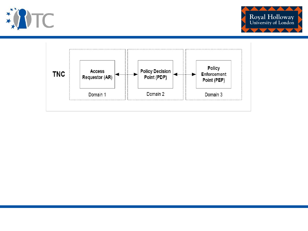
www.opentc.net
16
th
February 2007
47
The TNC architecture
•
Access Requestor (AR)
:
– The AR is the entity seeking access to a protected network.
•
Policy Decision Point (PDP)
:
– The PDP is the entity performing the decision-making regarding the AR’s
request, in light of the access policies.
•
Policy Enforcement Point (PEP):
– The PEP is the entity that enforces the decisions of the PDP regarding
network access.
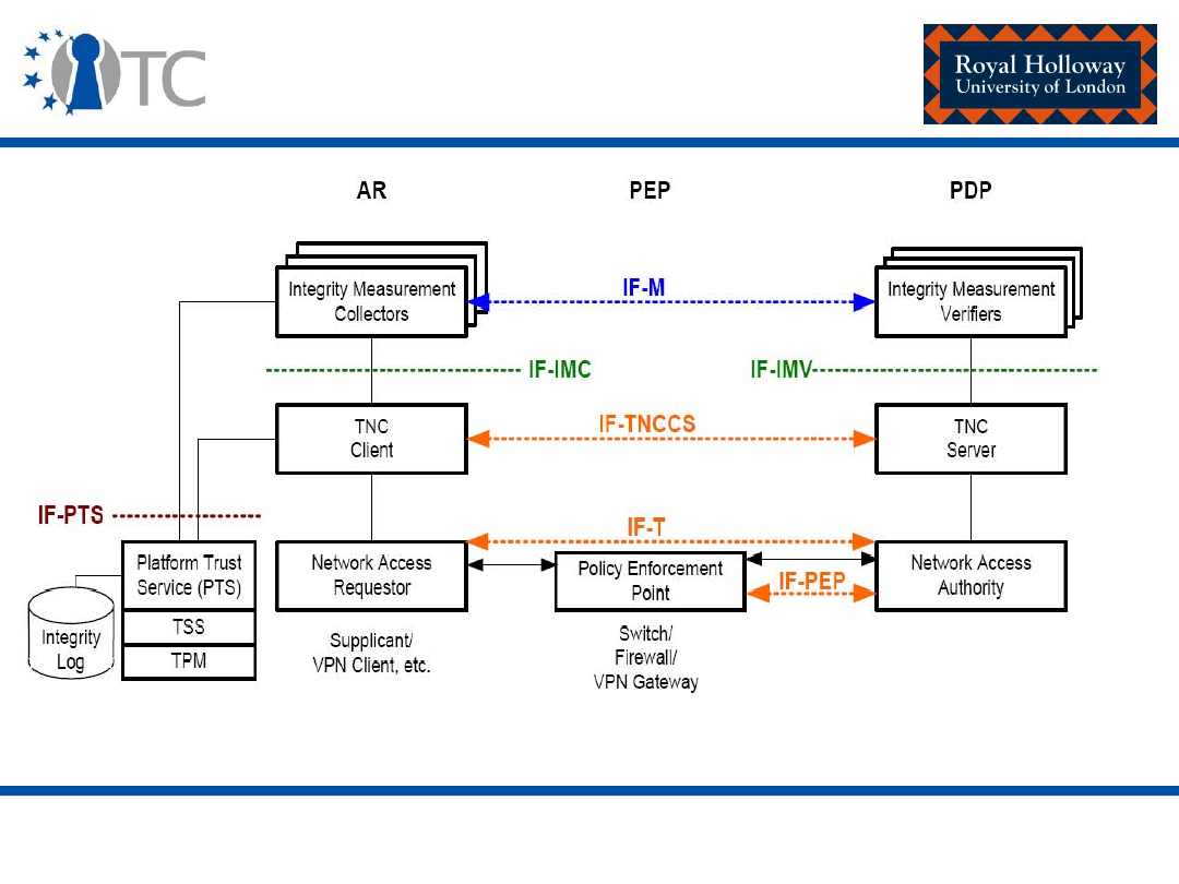
www.opentc.net
16
th
February 2007
48
The TNC architecture

www.opentc.net
16
th
February 2007
49
The TNC architecture - AR
• Network Access Requestor (NAR):
– The NAR is the component responsible for establishing network access.
– The NAR can be implemented as a software component that runs on an
AR, negotiating its connection to a network.
– There may be several NARs on a single AR to handle connections to
different networks.
• TNC Client (TNCC):
– The TNCC is a software component that runs on an AR, aggregating
integrity measurements from IMCs and orchestrating the reporting of
local platform and IMC measurements (integrity check handshake).
– Here, integrity check handshake could be an example of a TCG
attestation protocol in the context of the TNC.

www.opentc.net
16
th
February 2007
50
The TNC architecture - AR
• Integrity Measurement Collector (IMC):
– The IMC is a software component that runs on an AR, measuring security
aspects of the AR's integrity.
– Examples include the anti-virus parameters on the Access Requestor,
personal firewall status, software versions, and other security aspects of
the AR.
– Note that the TNC architecture is designed for multiple IMCs to interact
with a single (or multiple) TNC-Client/Server, thereby allowing customers
to deploy complex integrity policies involving a range of vendor products.

www.opentc.net
16
th
February 2007
51
The TNC architecture - PDP
• Network Access Authority (NAA):
– The NAA is a component that decides whether an Access Requestor (AR)
should be granted access.
– The NAA consults a TNC Server to determine whether the AR's integrity
measurements comply with the PDP's security policy.
– In many cases, an NAA will be included within a AAA Server but this is not
required.
• TNC Server (TNCS):
– The TNCS is a component that manages the flow of messages between
IMVs and IMCs, gathers IMV action recommendations from IMVs, and
combines those recommendations (based on policy) into an overall TNCS
action-recommendation to the NAA.
• Integrity Measurement Verifier (IMV):
– The IMV is a component that verifies a particular aspect of the AR’s
integrity, based on measurements received from IMCs and/or other data.

www.opentc.net
16
th
February 2007
52
The TNC architecture - PEP
• The PEP is the component which controls access to a protected
network.
• The PEP consults the PDP to determine whether access should be
granted.

www.opentc.net
16
th
February 2007
53
The TNC architecture - Phases in
network access control
Assessment
• In this phase, the IMVs perform the verification of the AR following
the policies set by the Network Administrator and if necessary
delivers remediation instructions to the IMCs.
Isolation
• If the AR has been authenticated and is recognised to be one that
has some privileges on the network but has not passed the integrity-
verification by the IMV, the PDP may return instructions to the PEP to
redirect the AR to an isolation environment where the AR can obtain
integrity-related updates.
Remediation
• The process of the AR obtaining corrections to its current platform
configuration in order to being in in line with the PDP’s requirements
for network access.
www.opentc.net
16
th
February 2007
54
The information in this document is provided “as is”, and no guarantee or
warranty is given that the information is fit for any particular purpose.
The user thereof uses the information at its sole risk and liability.
The
support for the development of the course material is provided
by the OpenTC project
which is co-financed by the EC.
If you need further information, please visit our website
www.opentc.net or contact the coordinator:
Technikon Forschungs- und Planungsgesellschaft mbH
Richard-Wagner-Strasse 7, 9500 Villach, AUSTRIA
Tel.
+
43 4242 23355 – 0
Fax.
+
43 4242 23355 – 77
Email coordination@opentc.net
Open_TC EC Contract No: IST-
027635

Steve Hand
University of Cambridge
Computer Laboratory
Protection,
Protection,
Protection,
Protection,
Virtualization
Virtualization
Virtualization
Virtualization
and Xen
and Xen
and Xen
and Xen

RHUL 23/02/07
2
Protection in Computer Systems
Protection in Computer Systems
Protection in Computer Systems
Protection in Computer Systems
Generally want to prevent ‘unauthorized’:
– Release of information
• E.g. reading or leaking data, violating privacy legislation,
using proprietary software
• Covert channels
– Modification of information
• Changing or removing data (or access rights)
– Denial of service
• Causing a crash, high load (e.g. fork bomb)
Protection usually imposed on accesses by
subjects (e.g. users) on objects (e.g. files)

RHUL 23/02/07
3
Some Principles
Some Principles
Some Principles
Some Principles…
…
…
…
e.g. Saltzer & Schroeder Proc. IEEE Sept 75
– Design should be public
– Default should be no access
– Check for current authority
– Give subjects minimum possible privilege
– Mechanisms should be simple, uniform and built
into lowest layers
– Should be psychologically acceptable
– Cost of circumvention should be high

RHUL 23/02/07
4
The
The
The
The “
“
“
“Standard
Standard
Standard
Standard”
”
”
” Design
Design
Design
Design
Separation of user-code and system-code
– “applications” versus “operating system”
– “processes” versus “kernel”
– Usually requires (at least some) hardware support
Separation of mechanism from policy
– Most privileged part of system must enforce (at
least some) protection / access checks...
– But desire for simplicity and flexibility
– (c/f “Hydra: The Kernel of a Multiprocessor
Operating System”, Wulf, 1974)
RHUL 23/02/07
5
Traditionally 2
Traditionally 2
Traditionally 2
Traditionally 2----Levels
Levels
Levels
Levels…
…
…
…
Process
Process
Process
Privileged
Un-Privileged
Supervisor (Atlas, 1961)
Nucleus (RC 4000, 1970)
Kernel (UNIX, 1971)
Micro-Kernel (Mach, 1981)
HARDWARE

RHUL 23/02/07
6
…
…
…
… but also get others
but also get others
but also get others
but also get others
– E.g. Dijkstra’s “THE” operating system
• Extended 6-layer structure, with layer 0 (most privileged)
handles interrupts and context switches
• L3 handles I/O devices, L4 deals with user programs
– E.g. Multics
• Many (8-64) concentric “rings” of privilege
• Ring x < y has strictly more privilege
– E.g. Hydra, CAP
• Capability based => no implied hierarchy (subset-of
relation) between protection domains
• (~direct implementation of principle of least privilege)

RHUL 23/02/07
7
A Fundamental Security Problem?
A Fundamental Security Problem?
A Fundamental Security Problem?
A Fundamental Security Problem?
Discretionary controls assume users act in
authorized way.
– Vulnerable applications or careless users may
allow malicious code to enter and compromise a
system
– Accounts for success of most email viruses, man-
in-the-middle, and phishing attacks
– Susceptible to attacks by root
Usual ‘fix’ for this is mandatory access controls.

RHUL 23/02/07
8
DAC
DAC
DAC
DAC vs
vs
vs
vs MAC
MAC
MAC
MAC
DAC
•Object owner has full power
•Complete trust in users
•Decisions are based only
on user id and object
ownerships
•Impossible to control data
flow
MAC
•Object owner CAN have some
power
•Only trust in administrators
•Objects and tasks themselves
can have ids
•Makes data flow control possible
Impossible to do MAC on top of DAC (but not vice versa)

RHUL 23/02/07
9
Traditional MAC
Traditional MAC
Traditional MAC
Traditional MAC
• Classify users and objects with labels
• Define a security policy based on the
relationship of labels, and allowed state
transitions.
• Enforce security policy like there is no
tomorrow
• For example: Bell-LaPadula model for
confidentiality.

RHUL 23/02/07
10
Enter Flask
Enter Flask
Enter Flask
Enter Flask…
…
…
…
BLP is just a model – to implement this need a system.
E.g. ‘Flask’, based on a general MAC architecture.
• Defines what should be available and not how it
should be implemented
• Supports flexible security policies, “user friendly”
security language (syntax)
• Separates policies from enforcement
• Contains a Security Server and Object Managers
• (c/f Hydra and others ;-)

RHUL 23/02/07
11
Three Components to Flask
Three Components to Flask
Three Components to Flask
Three Components to Flask
The Security Server (SS:-):
– maintains all security policies and is implemented
as a core (‘kernel’) subsystem
The Object Manager:
– enforces security policies as defined by the SS,
integrated into kernel subsystems such as process
management and IPC.
The Access Vector Cache:
– stores past SS policy requests/responses, used
for faster access
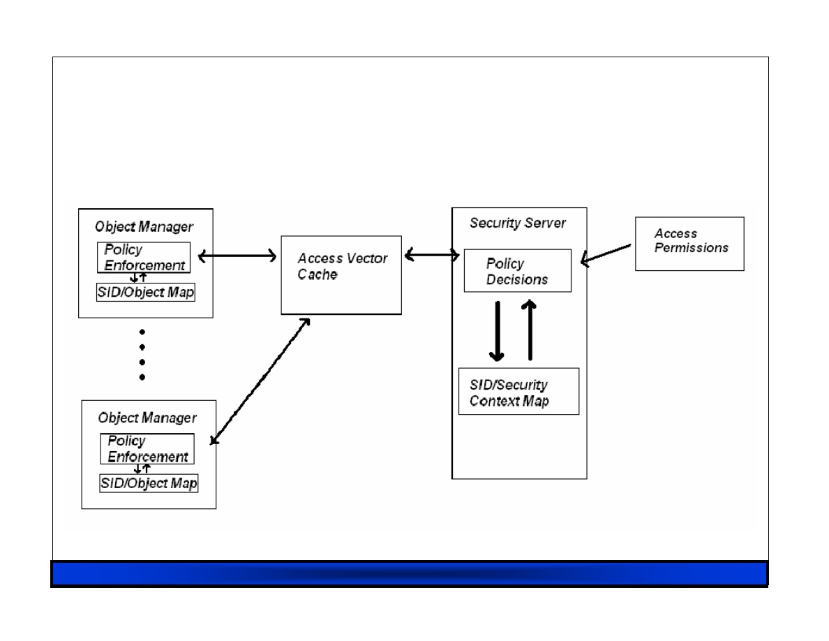
RHUL 23/02/07
12
Flask in a Diagram
Flask in a Diagram
Flask in a Diagram
Flask in a Diagram

RHUL 23/02/07
13
SELinux
SELinux
SELinux
SELinux’’’’s
s
s
s Implementation of Flask
Implementation of Flask
Implementation of Flask
Implementation of Flask
• SS Security Context contains:
– User ID, role, type and MLS classification
• (user ID is distinct from Linux’s native UID)
• Roles are for use with processes therefore
other objects such as files will have the
object_r role
• Type is to identify the type of object
• MLS classification is optional

RHUL 23/02/07
14
Problems with
Problems with
Problems with
Problems with SELinux
SELinux
SELinux
SELinux
• From a ‘security’ point of view, it’s good:
– versions aiming for EAL5+
• In practice however:
– Hooks embedded all over the place
• large and complex software artifact (linux) modified by
numerous and multifaceted hooks (policies)
• very difficult to verify (although people are trying)
– Policies difficult to write (and impossible to read)
– Usability always seems to come last
• Perhaps something else needed…
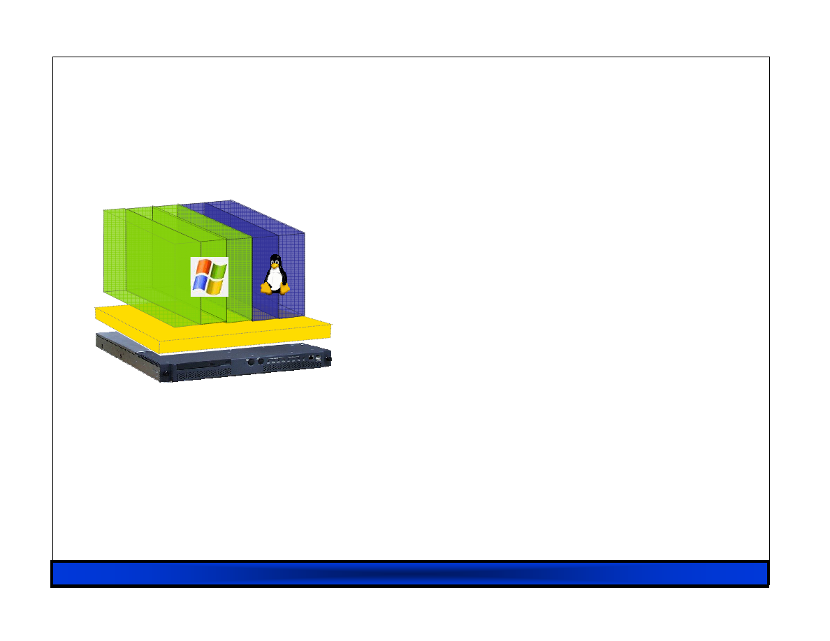
RHUL 23/02/07
15
What is Xen Anyway
What is Xen Anyway
What is Xen Anyway
What is Xen Anyway
?
?
?
?
• Open source hypervisor
– run multiple OSes on one machine
– dynamic sizing of virtual machine
– much improved manageability
• Pioneered paravirtualization
– modify OS kernel to run on Xen
– (applications mods not required)
– extremely low overhead (~1%)
• Massive development effort
– first (open source) release 2003.
– today have hundreds of talented
community developers

RHUL 23/02/07
16
Virtualization Benefits
Virtualization Benefits
Virtualization Benefits
Virtualization Benefits
Separating the OS from the hardware
– Users no longer forced to upgrade OS to run on latest
hardware
Device support is part of the platform
– Write one device driver rather than N
– Better for system reliability/availability
– Faster to get new hardware deployed
Enables “Virtual Appliances”
– Applications encapsulated with their OS
– Easy configuration and management

RHUL 23/02/07
17
Virtualization Possibilities
Virtualization Possibilities
Virtualization Possibilities
Virtualization Possibilities
Value-added functionality from outside OS:
– Fire-walling / network IDS / “inverse firewall”
– VPN tunnelling; LAN authentication
– Virus, mal-ware and exploit scanning
– OS patch-level status monitoring
– Performance monitoring and instrumentation
– Storage backup and snapshots
– Local disk as just a cache for network storage
– Carry your world on a USB stick
– Multi-level secure systems

RHUL 23/02/07
18
Xen 3.0 (5th Dec 2005)
Xen 3.0 (5th Dec 2005)
Xen 3.0 (5th Dec 2005)
Xen 3.0 (5th Dec 2005)
Secure isolation between VMs
Resource control and QoS
Latest stable is 3.0.4 (Dec 2006)
x86 32/PAE36/64 plus HVM;
IA64, Power
PV guest kernel needs to be ported
– User-level apps and libraries run unmodified
Execution performance close to native
Broad (linux) hardware support
Live Relocation of VMs between Xen nodes
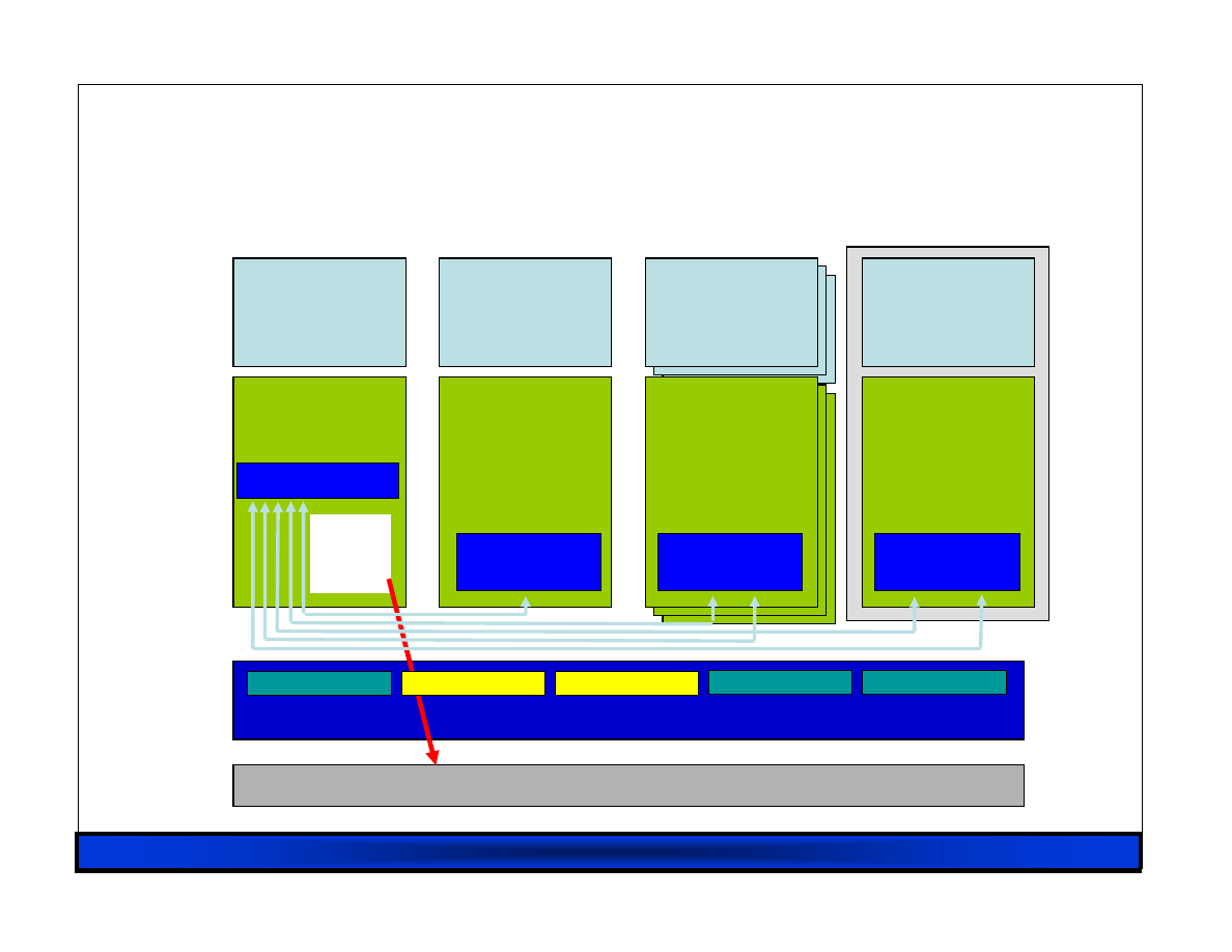
RHUL 23/02/07
19
Xen 3.0 Architecture
Xen 3.0 Architecture
Xen 3.0 Architecture
Xen 3.0 Architecture
Event Channel
Virtual MMU
Virtual CPU
Control IF
Hardware (SMP, MMU, physical memory, Ethernet, SCSI/IDE)
Native
Device
Drivers
GuestOS
(XenLinux)
Device
Manager &
Control s/w
VM0
GuestOS
(XenLinux)
Unmodified
User
Software
VM1
Front-End
Device Drivers
GuestOS
(XenLinux)
Unmodified
User
Software
VM2
Front-End
Device Drivers
Unmodified
GuestOS
(WinXP))
Unmodified
User
Software
VM3
Safe HW IF
Xen Virtual Machine Monitor
Back-End
HVM
x86_32
x86_64
IA64
AGP
ACPI
PCI
SMP
Front-End
Device Drivers

RHUL 23/02/07
20
Para
Para
Para
Para----Virtualization in Xen
Virtualization in Xen
Virtualization in Xen
Virtualization in Xen
Xen extensions to x86 arch
– Like x86, but Xen invoked for privileged ops
– Avoids binary rewriting
– Minimize number of privilege transitions into Xen
– Modifications relatively simple and self-contained
Modify kernel to understand virtualised env.
– Wall-clock time vs. virtual processor time
• Desire both types of alarm timer
– Expose real resource availability
• Enables OS to optimise its own behaviour

RHUL 23/02/07
21
x86 CPU virtualization
x86 CPU virtualization
x86 CPU virtualization
x86 CPU virtualization
Xen runs in ring 0 (most privileged)
Ring 1/2 for guest OS, 3 for user-space
– GPF if guest attempts to use privileged instr
Xen lives in top 64MB of linear addr space
– Segmentation used to protect Xen as switching page
tables too slow on standard x86
Hypercalls jump to Xen in ring 0
– Indirection via hypercall page allows flexibility
Guest OS may install ‘fast trap’ handler
– Direct user-space to guest OS system calls

RHUL 23/02/07
22
Para
Para
Para
Para----Virtualizing
Virtualizing
Virtualizing
Virtualizing the MMU
the MMU
the MMU
the MMU
Guest OSes allocate and manage own PTs
– Hypercall to change PT base
Xen must validate PT updates before use
– Allows incremental updates, avoids revalidation
Validation rules applied to each PTE:
1. Guest may only map pages it owns*
2. Pagetable pages may only be mapped RO
Xen traps PTE updates and emulates, or ‘unhooks’
PTE page for bulk updates
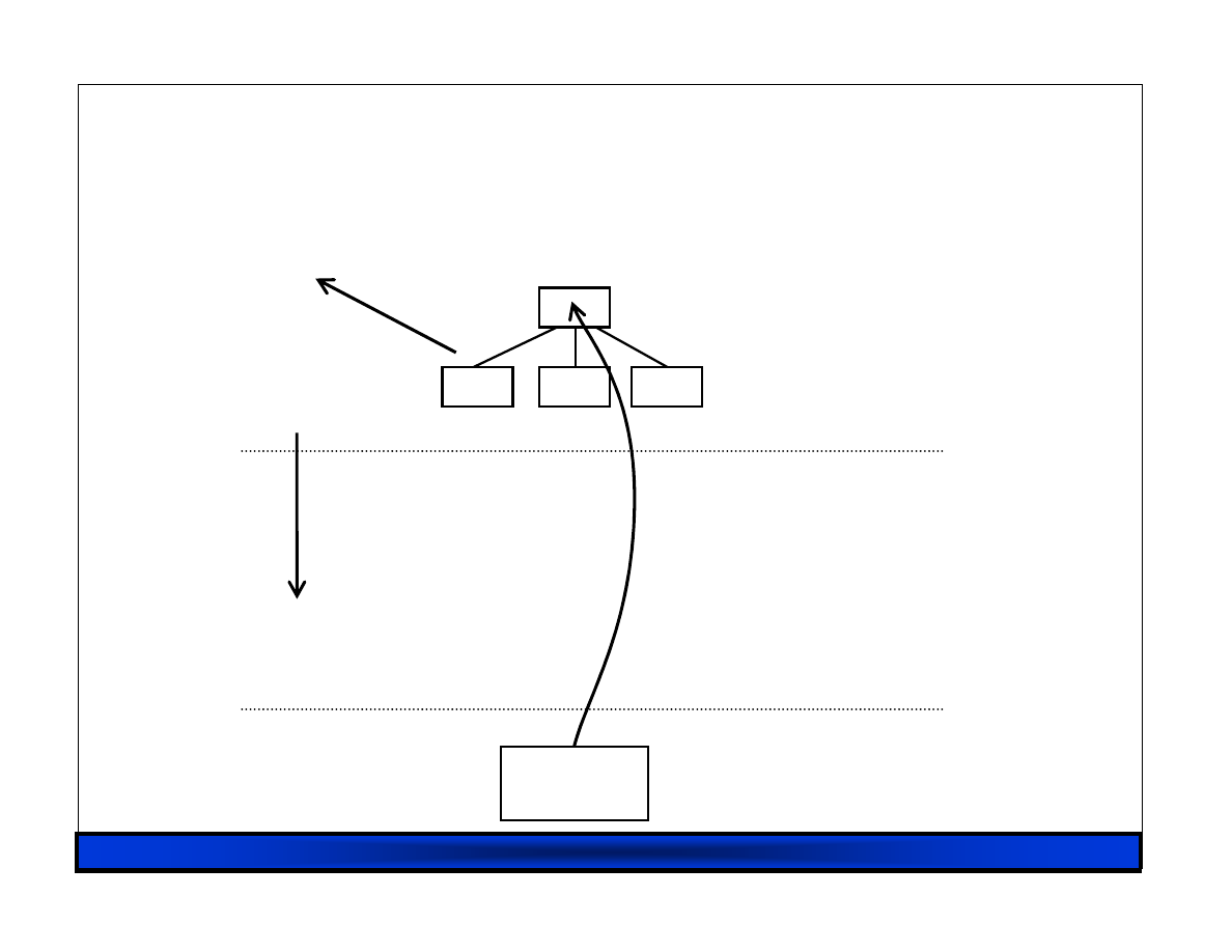
RHUL 23/02/07
23
Writeable Page Tables : 1
Writeable Page Tables : 1
Writeable Page Tables : 1
Writeable Page Tables : 1 –
–
–
– Write fault
Write fault
Write fault
Write fault
MMU
Guest OS
Xen VMM
Hardware
page fault
first guest
write
guest reads
Virtual
→
Machine
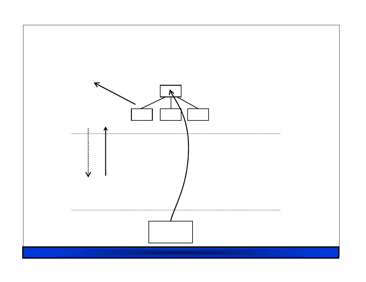
RHUL 23/02/07
24
Writeable Page Tables : 2
Writeable Page Tables : 2
Writeable Page Tables : 2
Writeable Page Tables : 2 –
–
–
– Emulate?
Emulate?
Emulate?
Emulate?
MMU
Guest OS
Xen VMM
Hardware
first guest
write
guest reads
Virtual
→
Machine
emulate?
yes
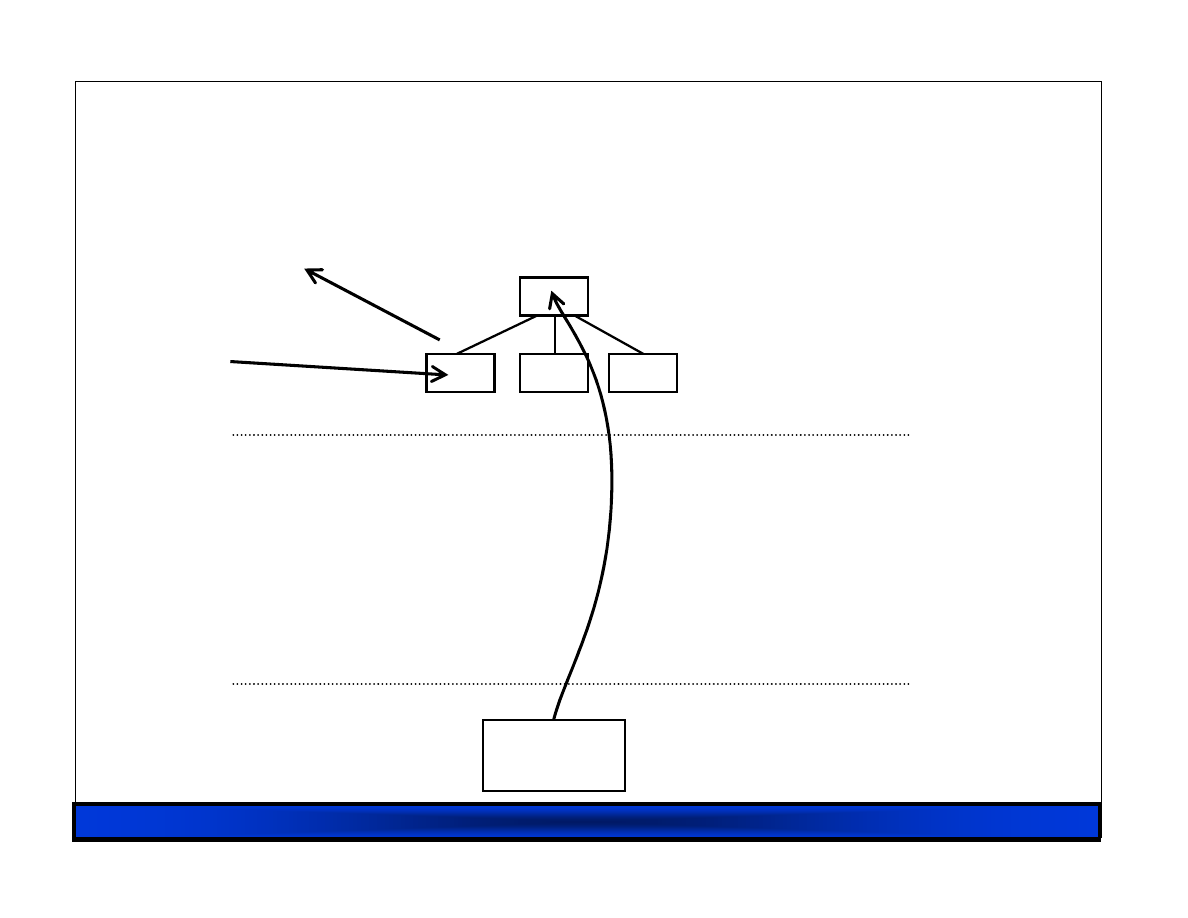
RHUL 23/02/07
25
Writeable Page Tables : 3
Writeable Page Tables : 3
Writeable Page Tables : 3
Writeable Page Tables : 3 –
–
–
– or Unhook
or Unhook
or Unhook
or Unhook
MMU
Guest OS
Xen VMM
Hardware
guest reads
Virtual
→
Machine
X
guest writes
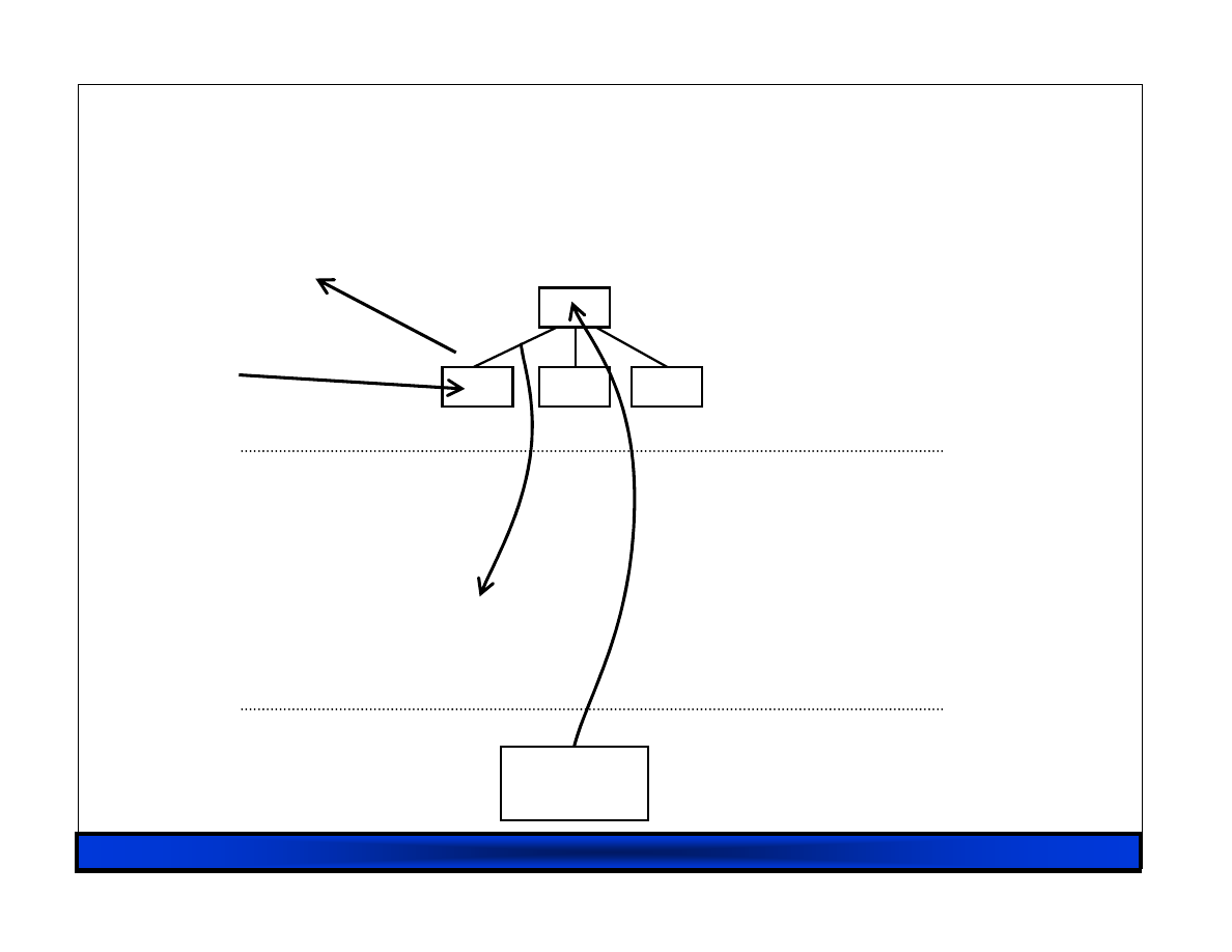
RHUL 23/02/07
26
Writeable Page Tables : 4
Writeable Page Tables : 4
Writeable Page Tables : 4
Writeable Page Tables : 4 –
–
–
– First Use
First Use
First Use
First Use
MMU
Guest OS
Xen VMM
Hardware
guest reads
Virtual
→
Machine
X
guest writes
page fault
RHUL 23/02/07
27
Writeable Page Tables : 5
Writeable Page Tables : 5
Writeable Page Tables : 5
Writeable Page Tables : 5 –
–
–
– Re
Re
Re
Re----Hook
Hook
Hook
Hook
MMU
Guest OS
Xen VMM
Hardware
guest reads
Virtual
→
Machine
guest writes
validate
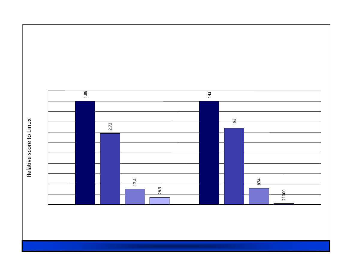
RHUL 23/02/07
28
MMU Micro
MMU Micro
MMU Micro
MMU Micro----Benchmarks
Benchmarks
Benchmarks
Benchmarks
L
X
V
U
Page fault (µs)
L
X
V
U
Process fork (µs)
0.0
0.1
0.2
0.3
0.4
0.5
0.6
0.7
0.8
0.9
1.0
1.1
lmbench results on Linux (L), Xen (X), VMWare Workstation (V), and UML (U)

RHUL 23/02/07
29
SMP Guest Kernels
SMP Guest Kernels
SMP Guest Kernels
SMP Guest Kernels
Xen supports multiple VCPUs per guest
– Virtual IPI’s sent via Xen event channels
– Currently up to 32 VCPUs supported
Simple hotplug/unplug of VCPUs
– From within VM or via control tools
– Optimize one active VCPU case by binary
patching spinlocks
NB: Many applications exhibit poor SMP
scalability – often better off running multiple
instances each in their own OS
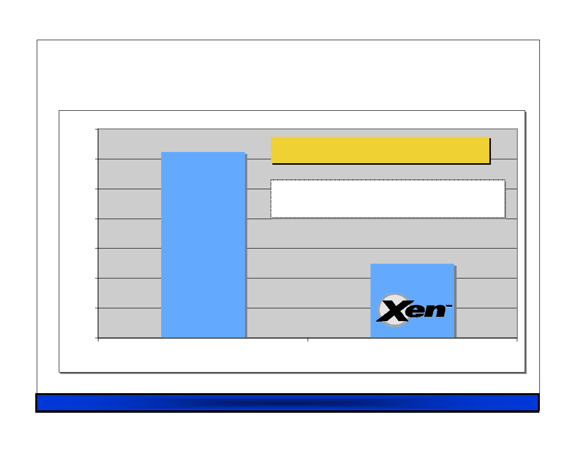
RHUL 23/02/07
30
Performance: SPECJBB
Performance: SPECJBB
Performance: SPECJBB
Performance: SPECJBB
7940
7960
7980
8000
8020
8040
8060
8080
Native
Xen
7940
7960
7980
8000
8020
8040
8060
8080
Native
Xen
Average 0.75% overhead
Average 0.75% overhead
Native
3 GHz Xeon 1GB memory / guest
2.6.9.EL vs. 2.6.9.EL-xen
3 GHz Xeon 1GB memory / guest
2.6.9.EL vs. 2.6.9.EL-xen
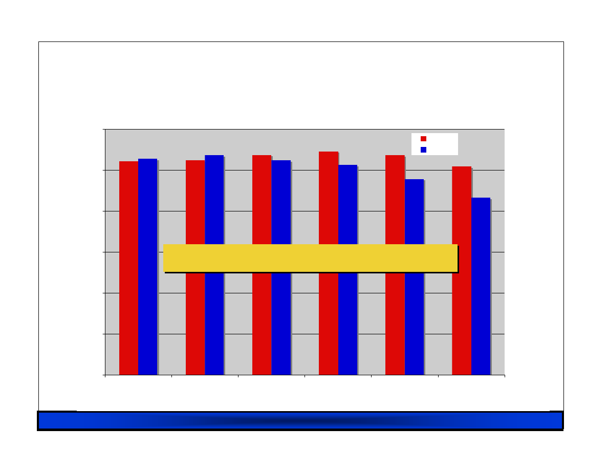
RHUL 23/02/07
31
Performance:
Performance:
Performance:
Performance: dbench
dbench
dbench
dbench
0
50
100
150
200
250
300
1
2
4
8
16
32
# CPUs
Native
Xen
< 5% Overhead up to 8 way SMP
< 5% Overhead up to 8 way SMP
RHUL 23/02/07
32
Kernel build
Kernel build
Kernel build
Kernel build
0
50
100
150
200
250
300
350
1
2
4
6
8
T
im
e
(
s
)
Native
Xen
32b PAE; Parallel make,
4 processes per CPU
5%
8%
13%
18%
23%
Source: XenSource, Inc: 10/06
# Virtual CPUs

RHUL 23/02/07
33
I/O Architecture
I/O Architecture
I/O Architecture
I/O Architecture
Xen IO-Spaces delegate guest OSes protected access
to specified h/w devices
– Virtual PCI configuration space
– Virtual interrupts
– (Need IOMMU for full DMA protection)
Devices are virtualised and exported to other VMs via
Device Channels
– Safe asynchronous shared memory transport
– ‘Backend’ drivers export to ‘frontend’ drivers
– Net: use normal bridging, routing, iptables
– Block: export any blk dev e.g. sda4,loop0,vg3
(Infiniband / Smart NICs for direct guest IO)
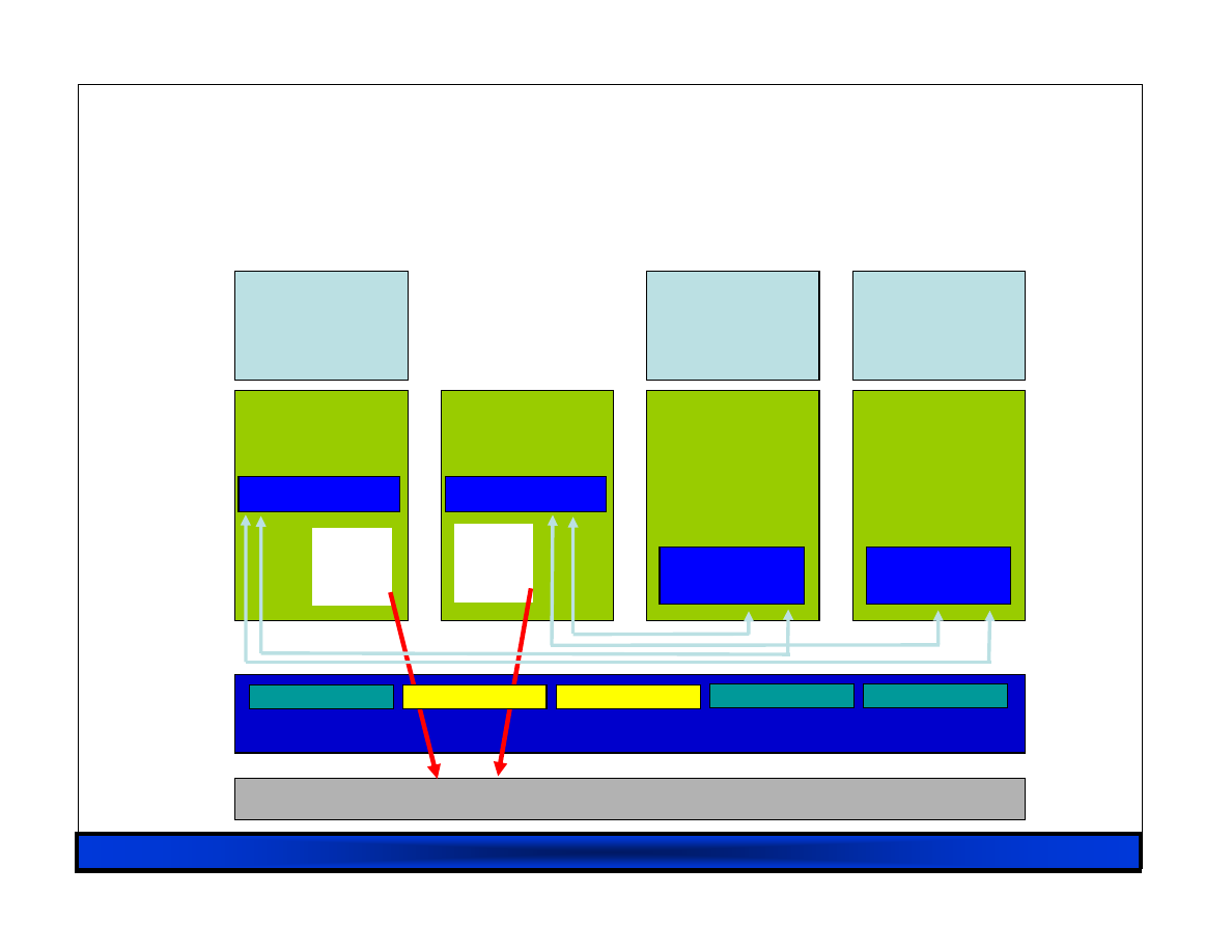
RHUL 23/02/07
34
Driver Domains
Driver Domains
Driver Domains
Driver Domains
Event Channel
Virtual MMU
Virtual CPU
Control IF
Hardware (SMP, MMU, physical memory, Ethernet, SCSI/IDE)
Native
Device
Driver
GuestOS
(XenLinux)
Device
Manager &
Control s/w
VM0
Native
Device
Driver
GuestOS
(XenLinux)
VM1
Front-End
Device Drivers
GuestOS
(XenLinux)
Unmodified
User
Software
VM2
Front-End
Device Drivers
GuestOS
(XenBSD)
Unmodified
User
Software
VM3
Safe HW IF
Xen Virtual Machine Monitor
Back-End
Back-End
Driver
Domain
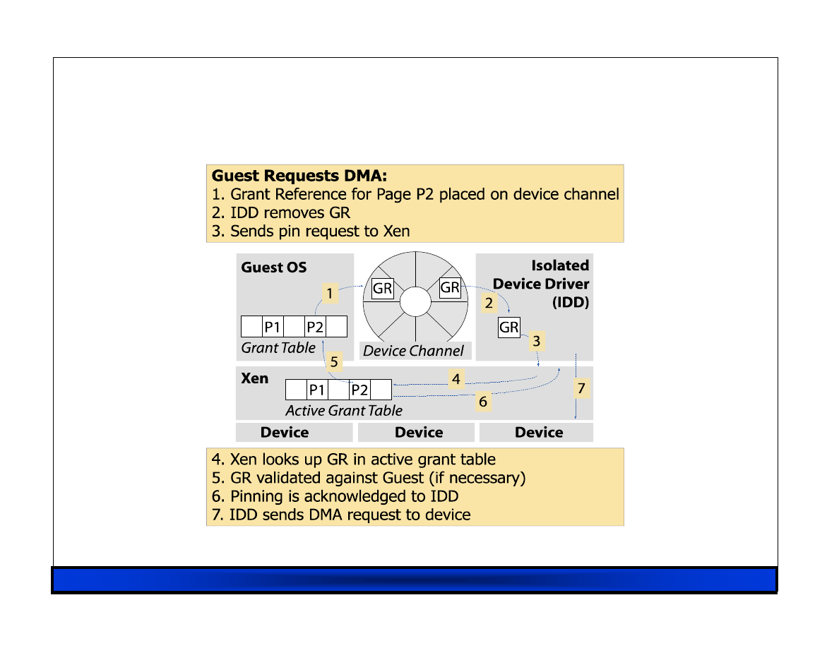
RHUL 23/02/07
35
Device Channel Interface
Device Channel Interface
Device Channel Interface
Device Channel Interface
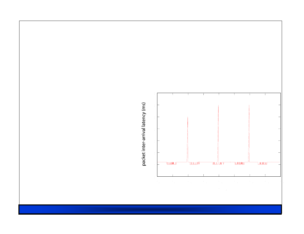
RHUL 23/02/07
36
Isolated Driver VMs
Isolated Driver VMs
Isolated Driver VMs
Isolated Driver VMs
Run device drivers in
separate domains
Detect failure e.g.
– Illegal access
– Timeout
Kill domain, restart
E.g. 275ms outage from
failed Ethernet driver
0
50
100
150
200
250
300
350
0
5
10
15
20
25
30
35
40
time (s)

RHUL 23/02/07
37
Hardware Virtualization (1)
Hardware Virtualization (1)
Hardware Virtualization (1)
Hardware Virtualization (1)
Paravirtualization…
– has fundamental benefits… (c/f MS Viridian)
– but is limited to OSes with PV kernels.
Recently seen new CPUs from Intel, AMD
– enable safe trapping of ‘difficult’ instructions
– provide additional privilege layers (“rings”)
– currently shipping in most modern server, desktop
and notebook systems
Solves part of the problem, but…

RHUL 23/02/07
38
Hardware Virtualization (2)
Hardware Virtualization (2)
Hardware Virtualization (2)
Hardware Virtualization (2)
CPU is only part of the system
– also need to consider memory and I/O
Memory:
– OS wants contiguous physical memory, but Xen needs to
share between many OSes
– Need to dynamically translate between guest physical and
‘real’ physical addresses
– Use shadow page tables to mirror guest OS page tables
(and implicit ‘no paging’ mode)
Xen 3.0 includes software shadow page tables; future
x86 processors will include hardware support.

RHUL 23/02/07
39
Hardware Virtualization (3)
Hardware Virtualization (3)
Hardware Virtualization (3)
Hardware Virtualization (3)
Finally we need to solve the I/O issue
– non-PV OSes don’t know about Xen
– hence run ‘standard’ PC ISA/PCI drivers
Just emulate devices in software?
– complex, fragile and non-performant…
– … but ok as backstop mechanism.
Better:
– add PV (or “enlightened”) device drivers to OS
– well-defined driver model makes this relatively easy
– get PV performance benefits for I/O path

RHUL 23/02/07
40
Xen 3: Hardware Virtual Machines
Xen 3: Hardware Virtual Machines
Xen 3: Hardware Virtual Machines
Xen 3: Hardware Virtual Machines
Enable Guest OSes to be run without modification
– E.g. legacy Linux, Solaris x86, Windows XP/2003
CPU provides vmexits for certain privileged instrs
Shadow page tables used to virtualize MMU
Xen provides simple platform emulation
– BIOS, apic, iopaic, rtc, net (pcnet32), IDE emulation
Install paravirtualized drivers after booting for high-
performance IO
Possibility for CPU and memory paravirtualization
– Non-invasive hypervisor hints from OS
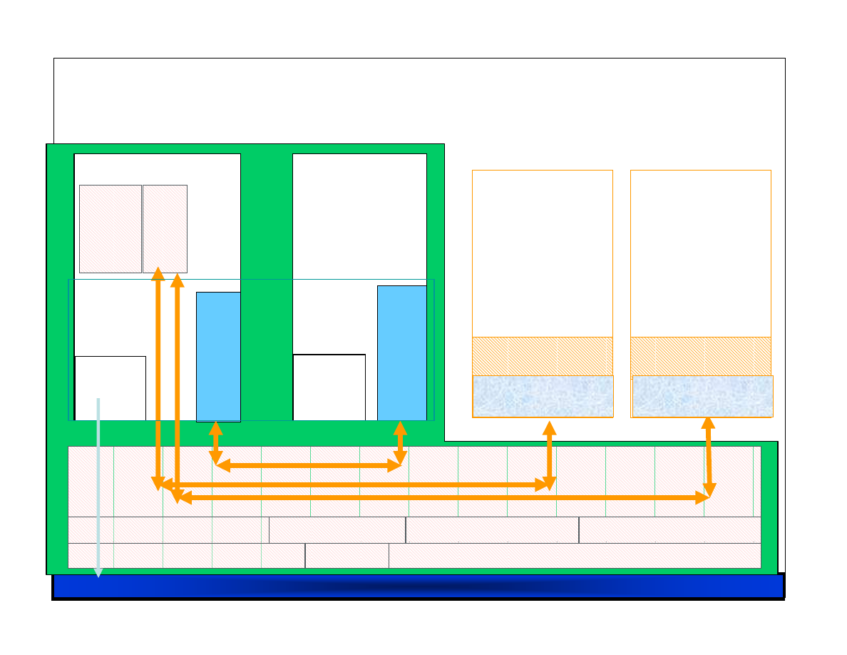
RHUL 23/02/07
41
Native
Device
Drivers
C
o
n
tr
o
l
P
a
n
e
l
(x
m
/x
e
n
d
)
F
ro
n
t e
n
d
V
ir
tu
a
l
D
ri
v
e
rs
Linux xen64
D
e
v
ic
e
M
o
d
e
ls
Guest BIOS
Unmodified OS
Domain
N
Linux xen64
Callback / Hypercall
VMExit
Virtual Platform
0D
B
a
c
k
e
n
d
V
ir
tu
a
l d
ri
v
e
r
Native
Device
Drivers
Domain
0
Event channel
0P
1/3P
3P
I/O: PIT, APIC, PIC, IOAPIC
Processor
Memory
Control Interface
Hypercalls
Event Channel
Scheduler
Guest BIOS
Unmodified OS
VMExit
Virtual Platform
3D
HVM Architecture
HVM Architecture
HVM Architecture
HVM Architecture
Guest VM (HVM)
(32-bit mode)
Guest VM (HVM)
(64-bit mode)
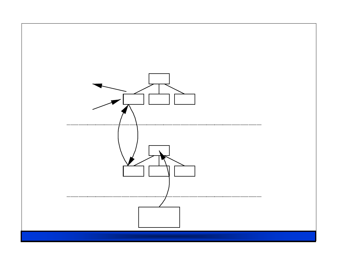
RHUL 23/02/07
42
MMU Virtualization : Shadow
MMU Virtualization : Shadow
MMU Virtualization : Shadow
MMU Virtualization : Shadow----Mode
Mode
Mode
Mode
MMU
Accessed &
dirty bits
Guest OS
VMM
Hardware
guest writes
guest reads
Virtual
→
Pseudo-physical
Virtual
→
Machine
Updates

RHUL 23/02/07
43
Progressive Paravirtualization
Progressive Paravirtualization
Progressive Paravirtualization
Progressive Paravirtualization
• Hypercall API available to HVM guests
• Selectively add PV extensions to optimize
– Network and Block IO
– XenAPIC (event channels)
– MMU operations
• multicast TLB flush
• PTE updates (faster than page fault)
• page sharing
– Time (wall-clock and virtual time)
– CPU and memory hotplug
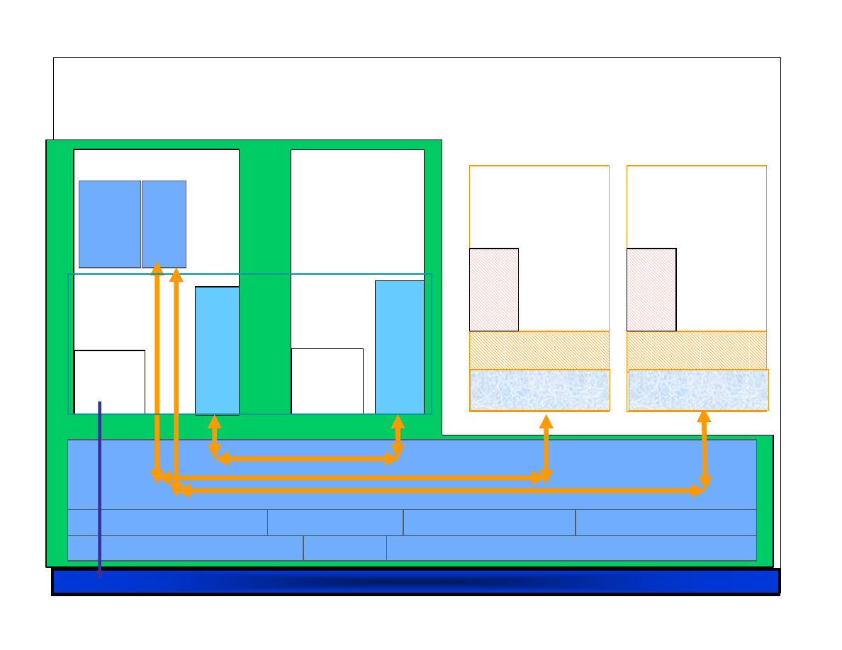
RHUL 23/02/07
44
Native
Device
Drivers
C
o
n
tr
o
l
P
a
n
e
l
(x
m
/x
e
n
d
)
F
ro
n
t e
n
d
V
ir
tu
a
l
D
ri
v
e
rs
Linux xen64
D
e
v
ic
e
M
o
d
e
ls
Guest BIOS
Unmodified OS
Domain
N
Linux xen64
Callback / Hypercall
VMExit
Virtual Platform
0D
B
a
c
k
e
n
d
V
ir
tu
a
l d
ri
v
e
r
Native
Device
Drivers
Domain
0
Event channel
0P
1/3P
3P
I/O: PIT, APIC, PIC, IOAPIC
Processor
Memory
Control Interface
Hypercalls
Event Channel
Scheduler
F
E
V
ir
tu
a
l
D
ri
v
e
rs
Guest BIOS
Unmodified OS
VMExit
Virtual Platform
F
E
V
ir
tu
a
l
D
ri
v
e
rs
3D
PIC/APIC/IOAPIC
emulation
Guest VM (HVM)
(32-bit mode)
Guest VM (HVM)
(64-bit mode)
Xen 3.0.3 Enhanced HVM I/O
Xen 3.0.3 Enhanced HVM I/O
Xen 3.0.3 Enhanced HVM I/O
Xen 3.0.3 Enhanced HVM I/O
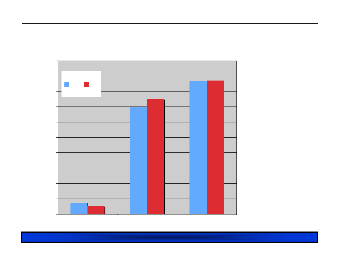
RHUL 23/02/07
45
0
100
200
300
400
500
600
700
800
900
1000
ioemu
PV-on-HVM
PV
M
b
/s
rx
tx
HVM I/O Performance
HVM I/O Performance
HVM I/O Performance
HVM I/O Performance
Measured with ttcp
(1500 byte MTU)
Emulated I/O PV on HVM Pure PV
Source:
XenSource, Sep 06
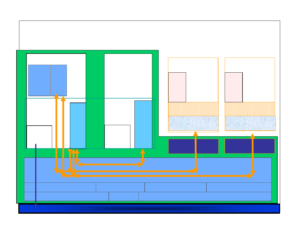
RHUL 23/02/07
46
Native
Device
Drivers
C
o
n
tr
o
l
P
a
n
e
l
(x
m
/x
e
n
d
)
F
ro
n
t e
n
d
V
ir
tu
a
l
D
ri
v
e
rs
Linux xen64
Guest BIOS
Unmodified OS
Domain
N
Linux xen64
Callback / Hypercall
VMExit
Virtual Platform
0D
Guest VM (HVM)
(32-bit mode)
B
a
c
k
e
n
d
V
ir
tu
a
l d
ri
v
e
r
Native
Device
Drivers
Domain
0
Event channel
0P
1/3P
3P
I/O: PIT, APIC, PIC, IOAPIC
Processor
Memory
Control Interface
Hypercalls
Event Channel
Scheduler
F
E
V
ir
tu
a
l
D
ri
v
e
rs
Guest BIOS
Unmodified OS
VMExit
Virtual Platform
Guest VM (HVM)
(64-bit mode)
F
E
V
ir
tu
a
l
D
ri
v
e
rs
3D
IO Emulation
IO Emulation
Even Better IO Emulation
Even Better IO Emulation
Even Better IO Emulation
Even Better IO Emulation…
…
…
…
D
e
v
ic
e
M
o
d
e
ls
PIC/APIC/IOAPIC
emulation

RHUL 23/02/07
47
Smart I/O Hardware
Smart I/O Hardware
Smart I/O Hardware
Smart I/O Hardware
Xen 3 PV and HVM guests work with high-
performance, but still a cost
– backend s/w needed for secure multiplexing
– can stress certain workloads (e.g. MPI)
Next step: smart I/O for virtualization
– make platform aware of virtualization
– (e.g. additional h/w protection for DMA coming
soon from Intel and AMD)
Or make devices aware of virtualization…

RHUL 23/02/07
48
Solarstorm inspired by user-level networking
– TCP/IP stack linked with user app
Smart NIC allows safe access from guest
– Onboard IOMMU for safe DMA
– NIC’s filter-table demuxes incoming packets to queue
– Queues get mapped into guests
Eliminates interrupts/syscalls/context switches
– Can also do zero-copy tx from guests
Slides courtesy of Greg Law at SolarFlare
E.g.
E.g.
E.g.
E.g. SolarFlare
SolarFlare
SolarFlare
SolarFlare Solarstorm
Solarstorm
Solarstorm
Solarstorm
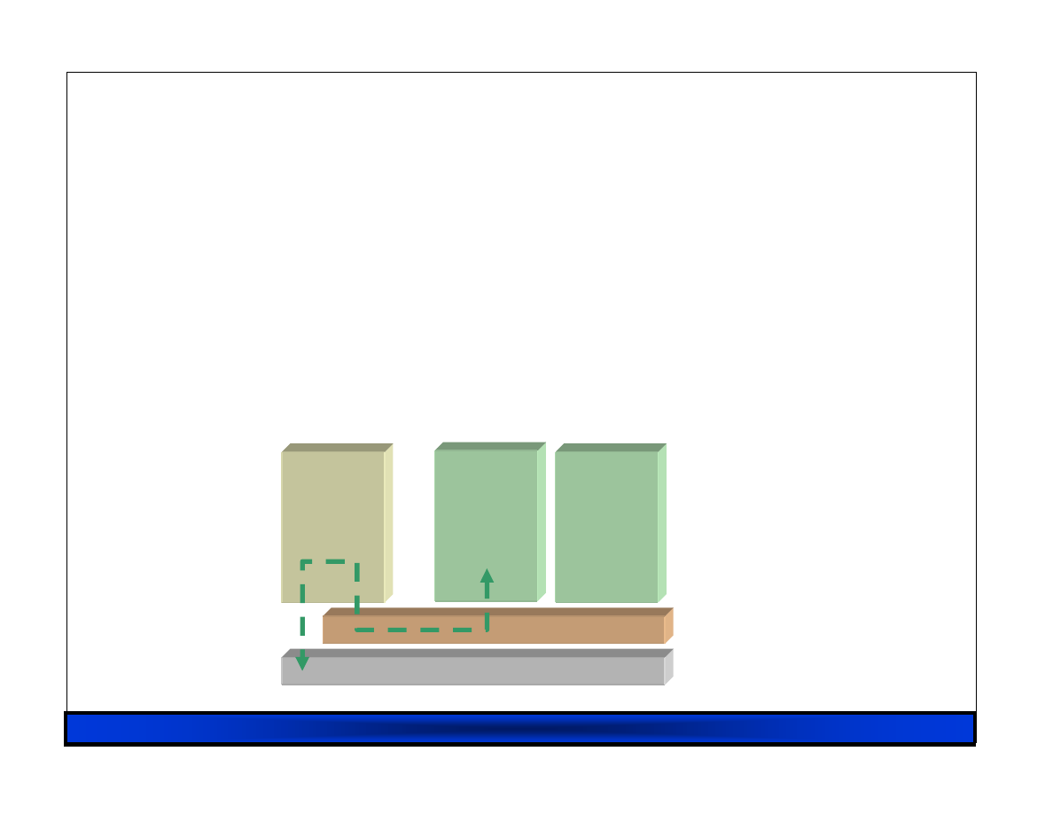
RHUL 23/02/07
49
All 'real' drivers live in Dom0
Guest kernels have pseudo drivers that talk to
Dom0 via the hypervisor
Necessary because only Dom0 is 'trusted'
Dom0
DomU
DomU
Hardware
Hypervisor
Traditional Xen: I/O via Dom0
Traditional Xen: I/O via Dom0
Traditional Xen: I/O via Dom0
Traditional Xen: I/O via Dom0

RHUL 23/02/07
50
Dom0
DomU
DomU
Hardware
Hypervisor
But with
But with
But with
But with Solarstorm
Solarstorm
Solarstorm
Solarstorm...
...
...
...
Accelerated routes set up in Dom0
DomU can access h/w directly + safely
– at least most of the time
– (still slow path via Dom0)

RHUL 23/02/07
51
HW Virtualization Summary
HW Virtualization Summary
HW Virtualization Summary
HW Virtualization Summary
CPU virtualization available today
– lets Xen support legacy/proprietary OSes
Additional platform protection imminent
– protect Xen from IO devices
– full IOMMU extensions coming soon
MMU virtualization also coming soon:
– avoid the need for s/w shadow page tables
– should improve performance and reduce complexity
Device virtualization arriving from various folks:
– networking already here (ethernet, infiniband)
– [remote] storage in the works (NPIV, VSAN)
– graphics and other devices sure to follow…

RHUL 23/02/07
52
Three Case Studies
Three Case Studies
Three Case Studies
Three Case Studies
Virtualization is a powerful technique
– One extra-level of indirection solves everything…
Next up we’ll cover three example uses:
– #1 Live Migration of Virtual Machines
– #2 Enhanced Virtual Block Devices
– #3 Demand-Emulation for Dynamic Taint-Tracking
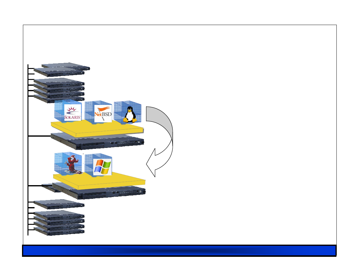
RHUL 23/02/07
53
#1. VM Relocation : Motivation
#1. VM Relocation : Motivation
#1. VM Relocation : Motivation
#1. VM Relocation : Motivation
VM relocation enables:
– High-availability
• Machine maintenance
– Load balancing
• Statistical multiplexing gain
Xen
Xen
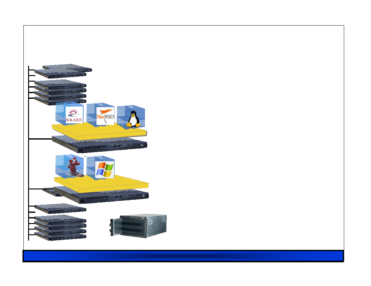
RHUL 23/02/07
54
Assumptions
Assumptions
Assumptions
Assumptions
Networked storage
– NAS: NFS, CIFS
– SAN: Fibre Channel
– iSCSI, network block dev
– drdb network RAID
Good connectivity
– common L2 network
– L3 re-routeing
Xen
Xen
Storage

RHUL 23/02/07
55
Challenges
Challenges
Challenges
Challenges
VMs have lots of state in memory
Some VMs have soft real-time requirements
– E.g. web servers, databases, game servers
– May be members of a cluster quorum
Minimize down-time
Performing relocation requires resources
Bound and control resources used
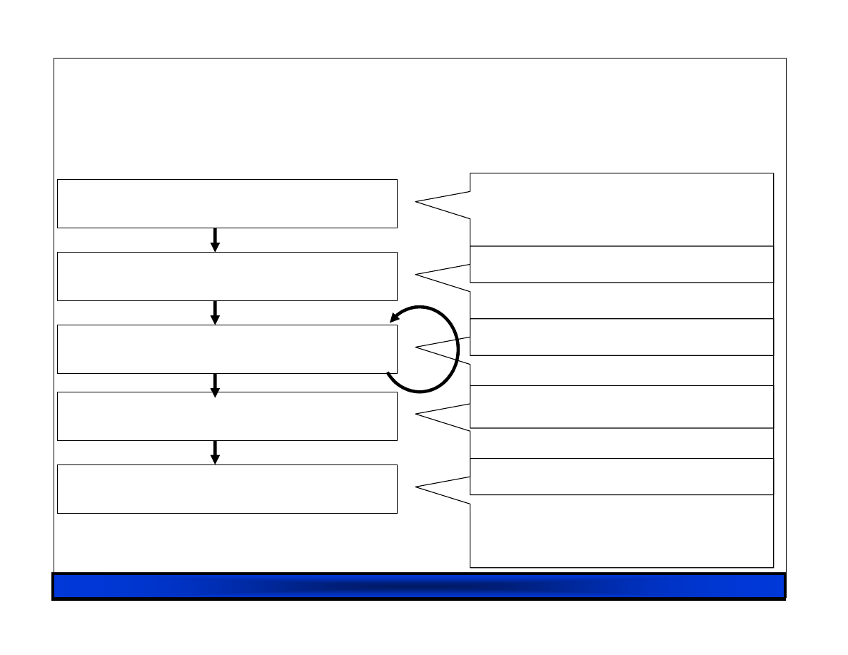
RHUL 23/02/07
56
Stage 0: pre-migration
Stage 1: reservation
Stage 2: iterative pre-copy
Stage 3: stop-and-copy
Stage 4: commitment
Relocation Strategy
Relocation Strategy
Relocation Strategy
Relocation Strategy
VM active on host A
Destination host selected
(Block devices mirrored)
Initialize container on
target host
Copy dirty pages in
successive rounds
Suspend VM on host A
Redirect network traffic
Synch remaining state
Activate on host B
VM state on host A
released

RHUL 23/02/07
57
Pre
Pre
Pre
Pre----Copy Migration: Round 1
Copy Migration: Round 1
Copy Migration: Round 1
Copy Migration: Round 1
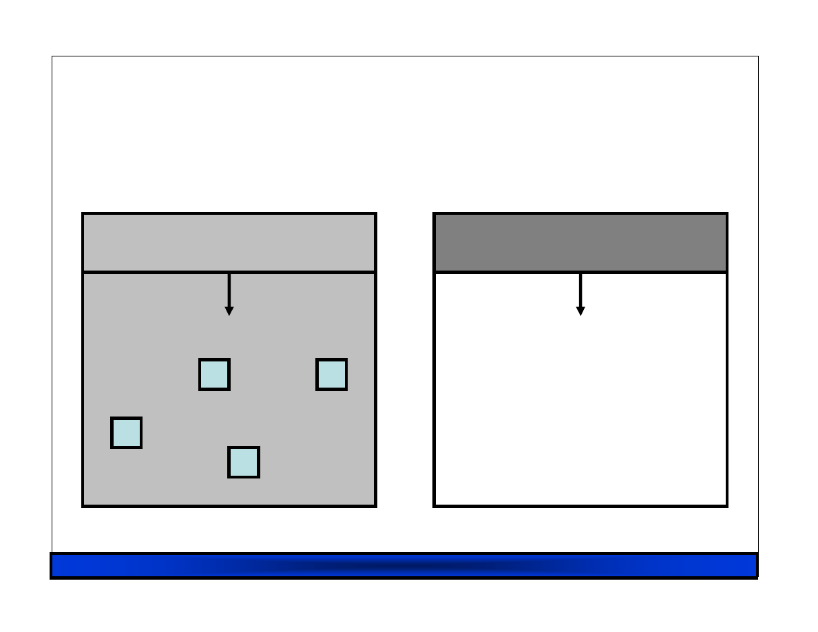
RHUL 23/02/07
58
Pre
Pre
Pre
Pre----Copy Migration: Round 1
Copy Migration: Round 1
Copy Migration: Round 1
Copy Migration: Round 1
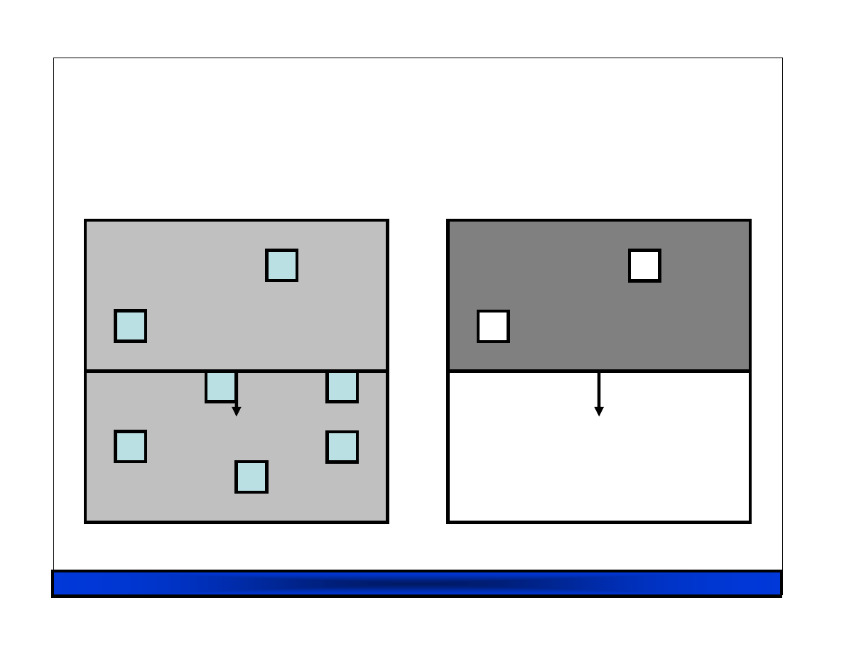
RHUL 23/02/07
59
Pre
Pre
Pre
Pre----Copy Migration: Round 1
Copy Migration: Round 1
Copy Migration: Round 1
Copy Migration: Round 1
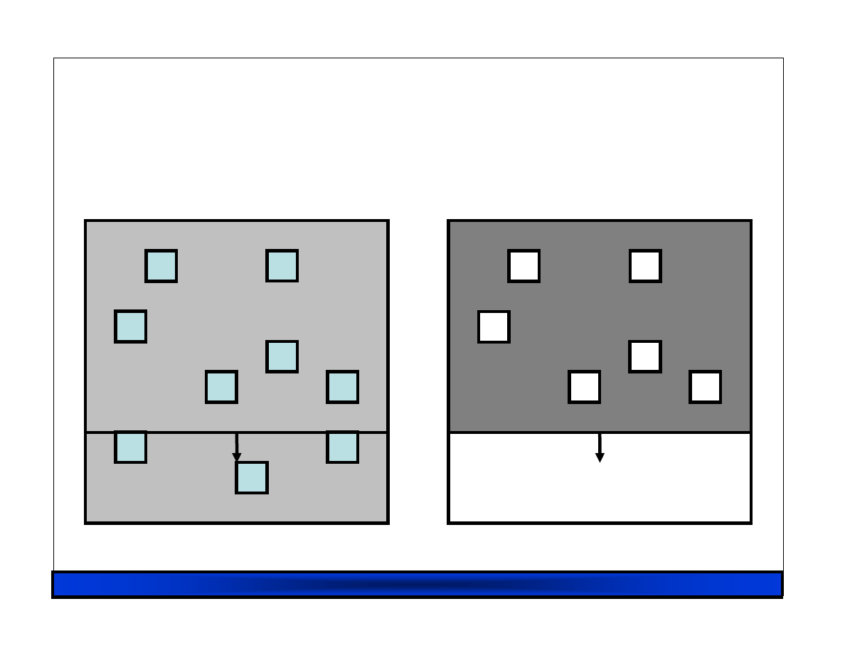
RHUL 23/02/07
60
Pre
Pre
Pre
Pre----Copy Migration: Round 1
Copy Migration: Round 1
Copy Migration: Round 1
Copy Migration: Round 1
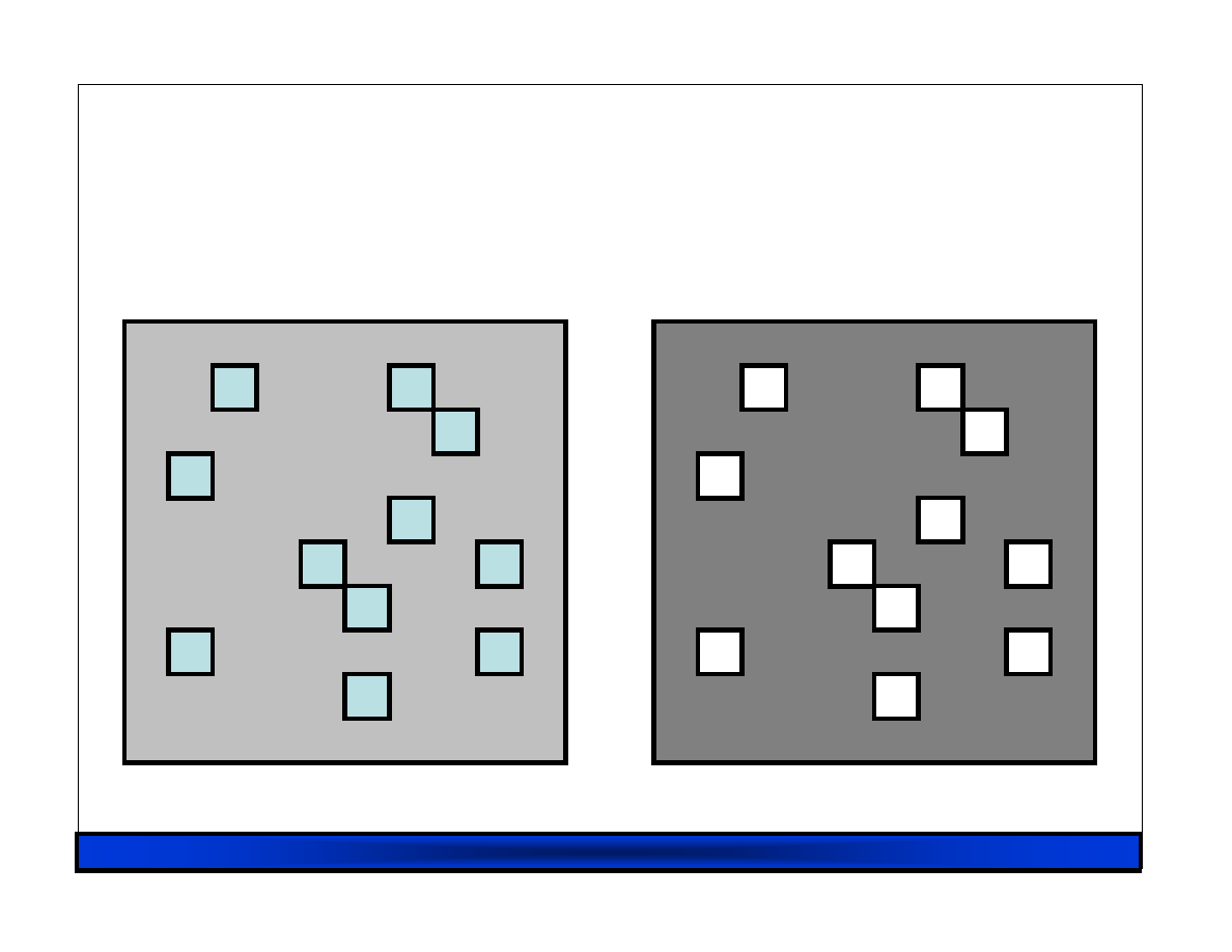
RHUL 23/02/07
61
Pre
Pre
Pre
Pre----Copy Migration: Round 1
Copy Migration: Round 1
Copy Migration: Round 1
Copy Migration: Round 1
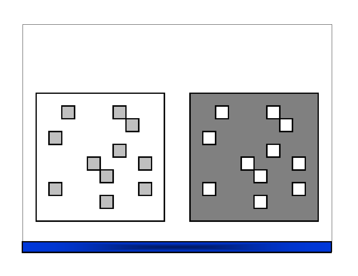
RHUL 23/02/07
62
Pre
Pre
Pre
Pre----Copy Migration: Round 2
Copy Migration: Round 2
Copy Migration: Round 2
Copy Migration: Round 2
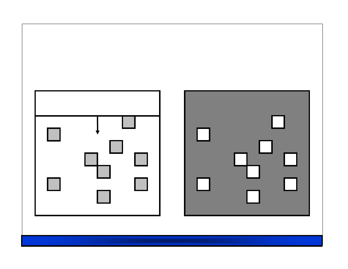
RHUL 23/02/07
63
Pre
Pre
Pre
Pre----Copy Migration: Round 2
Copy Migration: Round 2
Copy Migration: Round 2
Copy Migration: Round 2
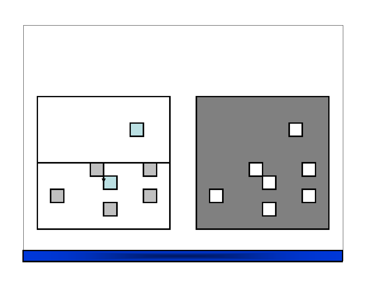
RHUL 23/02/07
64
Pre
Pre
Pre
Pre----Copy Migration: Round 2
Copy Migration: Round 2
Copy Migration: Round 2
Copy Migration: Round 2
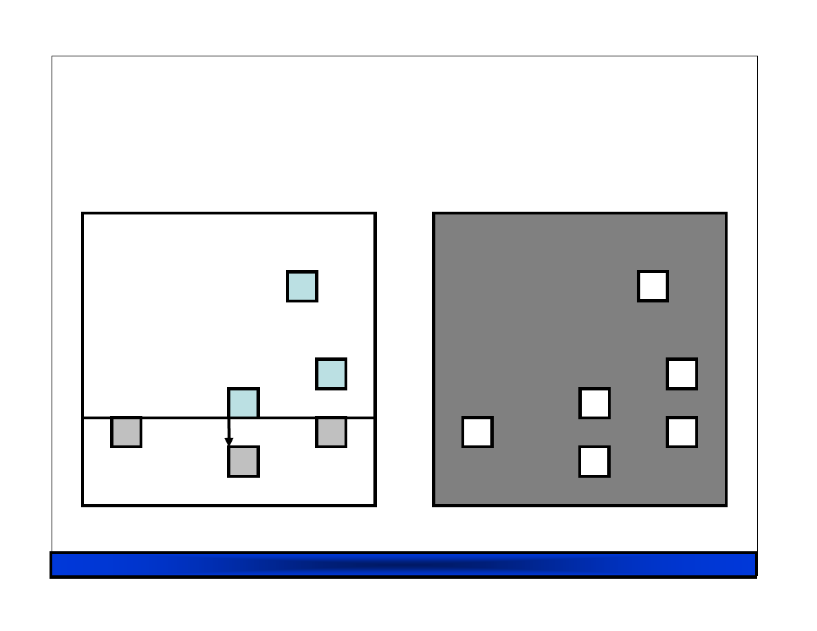
RHUL 23/02/07
65
Pre
Pre
Pre
Pre----Copy Migration: Round 2
Copy Migration: Round 2
Copy Migration: Round 2
Copy Migration: Round 2
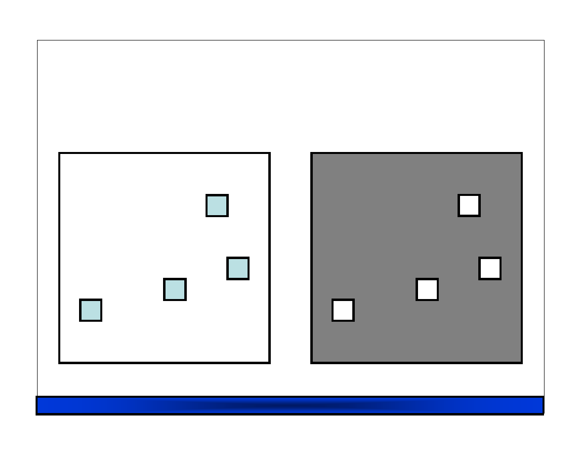
RHUL 23/02/07
66
Pre
Pre
Pre
Pre----Copy Migration: Round 2
Copy Migration: Round 2
Copy Migration: Round 2
Copy Migration: Round 2
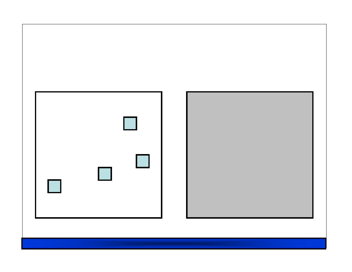
RHUL 23/02/07
67
Pre
Pre
Pre
Pre----Copy Migration: Final
Copy Migration: Final
Copy Migration: Final
Copy Migration: Final

RHUL 23/02/07
68
Writable Working Set
Writable Working Set
Writable Working Set
Writable Working Set
Pages that are dirtied must be re-sent
– Super hot pages
• e.g. process stacks; top of page free list
– Buffer cache
– Network receive / disk buffers
Dirtying rate determines VM down-time
– Shorter iterations
→
less dirtying
→
…

RHUL 23/02/07
69
Rate Limited Relocation
Rate Limited Relocation
Rate Limited Relocation
Rate Limited Relocation
Dynamically adjust resources committed to
performing page transfer
– Dirty logging costs VM ~2-3%
– CPU and network usage closely linked
E.g. first copy iteration at 100Mb/s, then
increase based on observed dirtying rate
– Minimize impact of relocation on server while
minimizing down-time
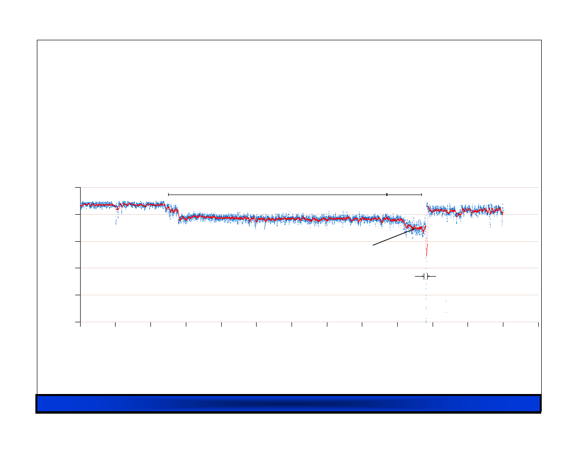
RHUL 23/02/07
70
Web Server Relocation
Web Server Relocation
Web Server Relocation
Web Server Relocation
Elapsed time (secs)
0
10
20
30
40
50
60
70
80
90
100
110
120
130
Throughput (Mbit/sec)
0
200
400
600
800
1000
Effect of Migration on Web Server Transmission Rate
Sample over 100ms
Sample over 500ms
512Kb files
100 concurrent clients
1st precopy, 62 secs
further iterations
9.8 secs
765 Mbit/sec
870 Mbit/sec
694 Mbit/sec
165ms total downtime
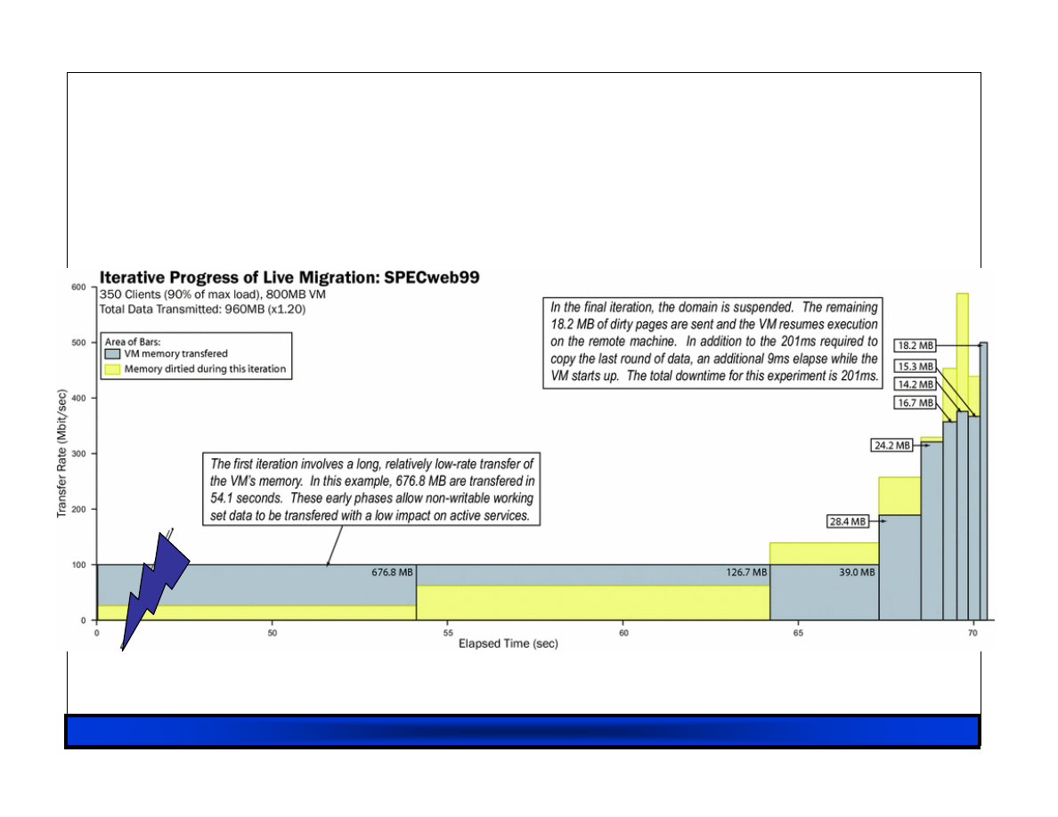
RHUL 23/02/07
71
Iterative Progress:
Iterative Progress:
Iterative Progress:
Iterative Progress: SPECWeb
SPECWeb
SPECWeb
SPECWeb
52s
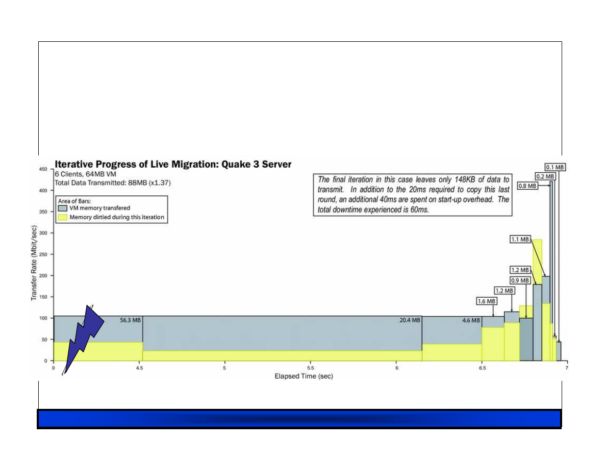
RHUL 23/02/07
72
Iterative Progress: Quake3
Iterative Progress: Quake3
Iterative Progress: Quake3
Iterative Progress: Quake3
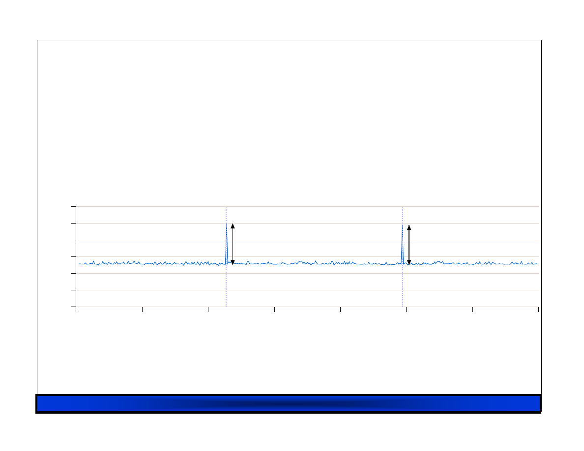
RHUL 23/02/07
73
Quake 3 Server relocation
Quake 3 Server relocation
Quake 3 Server relocation
Quake 3 Server relocation
Elapsed time (secs)
0
10
20
30
40
50
60
70
Packet flight time (secs)
0
0.02
0.04
0.06
0.08
0.1
0.12
Packet interarrival time during Quake 3 migration
Migration 1
downtime: 50ms
Migration 2
downtime: 48ms

RHUL 23/02/07
74
#2. Virtual Disk Storage
#2. Virtual Disk Storage
#2. Virtual Disk Storage
#2. Virtual Disk Storage
• LVM Logical Volumes are typically used to store
guest virtual disk images today
– Not as intuitive as using files
– Copy-on-write and snapshot support far from ideal
• Storing disk images in files using Linux’s “loop”
driver doesn’t work well
• The “Blktap” driver (Xen 3.0.3+) provides an
alternative :
– Allows all block requests to be serviced in user-space
using zero-copy AIO approach
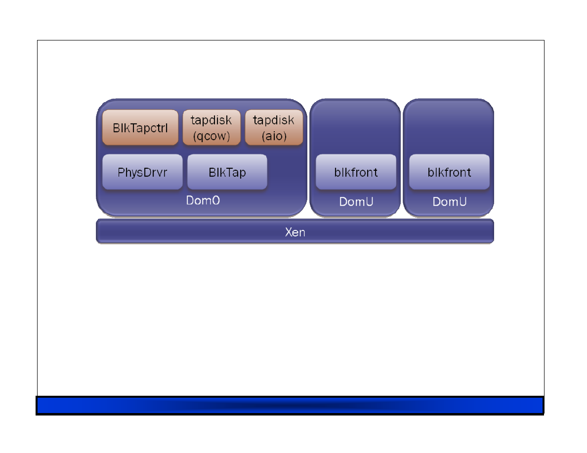
RHUL 23/02/07
75
Blktap and
Blktap and
Blktap and
Blktap and tapdisk
tapdisk
tapdisk
tapdisk plug
plug
plug
plug----ins
ins
ins
ins
• Plugins for qcow, vhd, vmdk and raw
• Native qcow format supports:
– Sparse allocation
– Copy-on-write
– Encryption
– Compression
• Great care taken over metadata write ordering
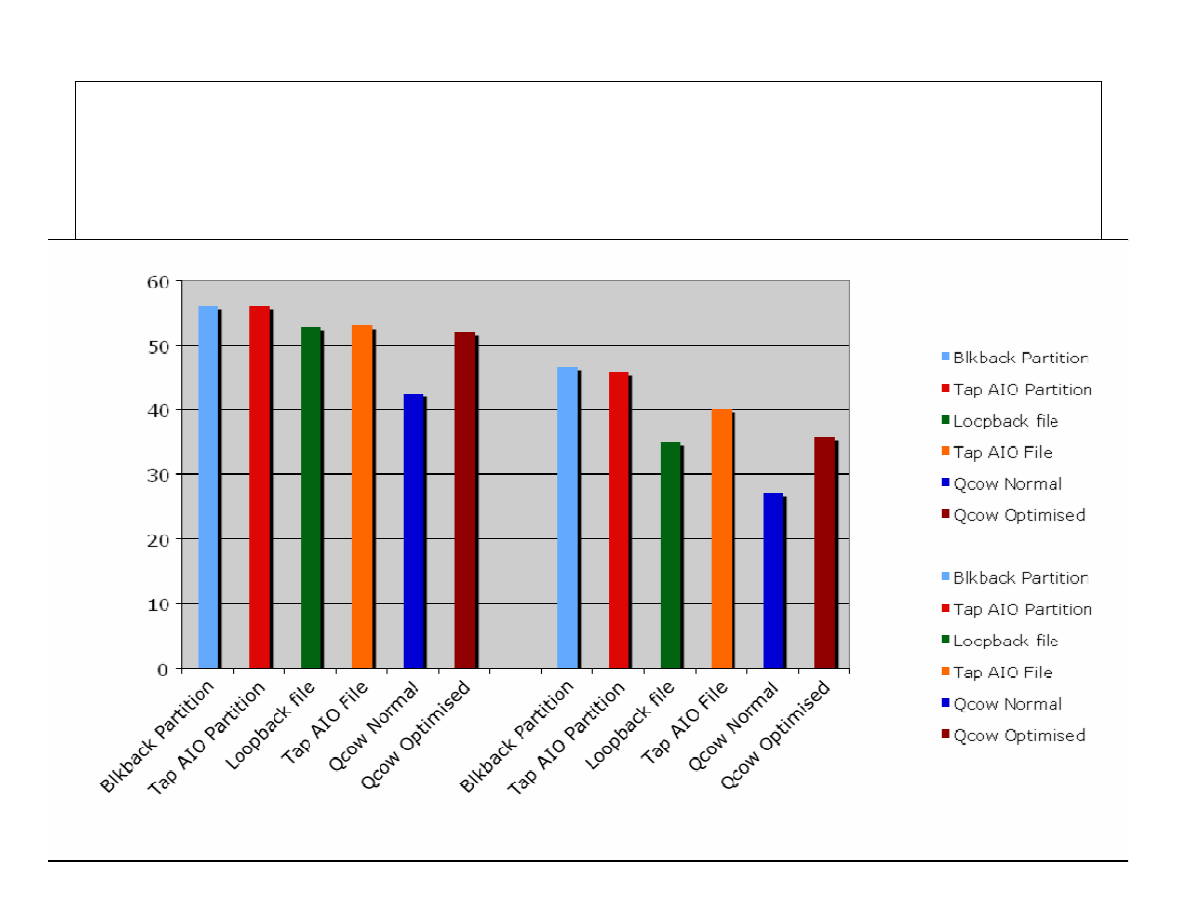
RHUL 23/02/07
76
Blktap IO performance
Blktap IO performance
Blktap IO performance
Blktap IO performance

RHUL 23/02/07
77
What about extending this?
VM clusters mean managing a lot of disk images in
a lot of locations!
Idea: Image management is a lot like virtual
memory -- and we can treat storage as a service.
Storage service “owns” local disks, and the OSes
that manage them.
Parallax virtualizes storage, fast snapshots, etc.
– Initially proposed in a HotOS’05 paper.
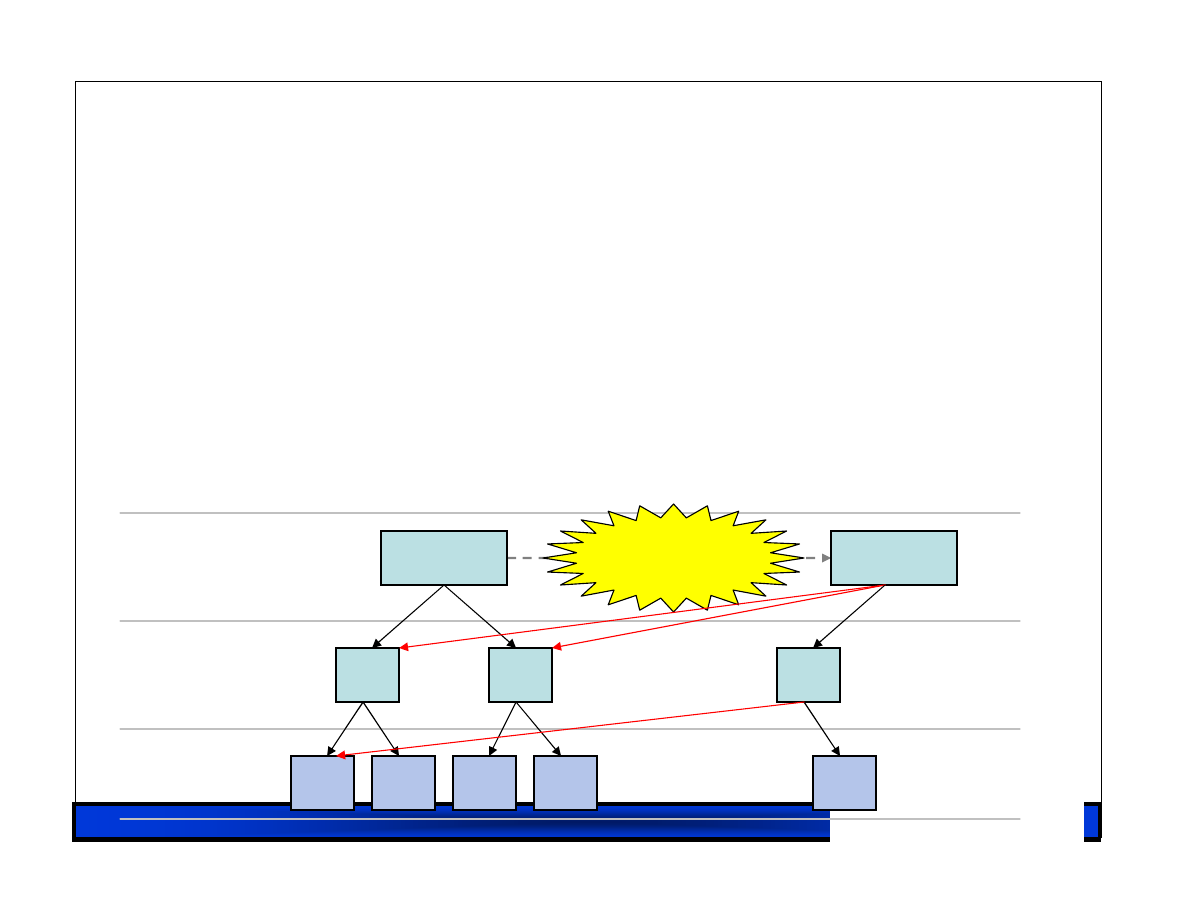
RHUL 23/02/07
78
Parallax: Virtual block mappings
Parallax: Virtual block mappings
Parallax: Virtual block mappings
Parallax: Virtual block mappings
Each virtual image is the root of a mapping trie.
No write sharing.
Snapshots are immutable.
Similar to what happens inside a filer, but
visible.
Root A
Root B
Snapshot!
Data
L2
L1
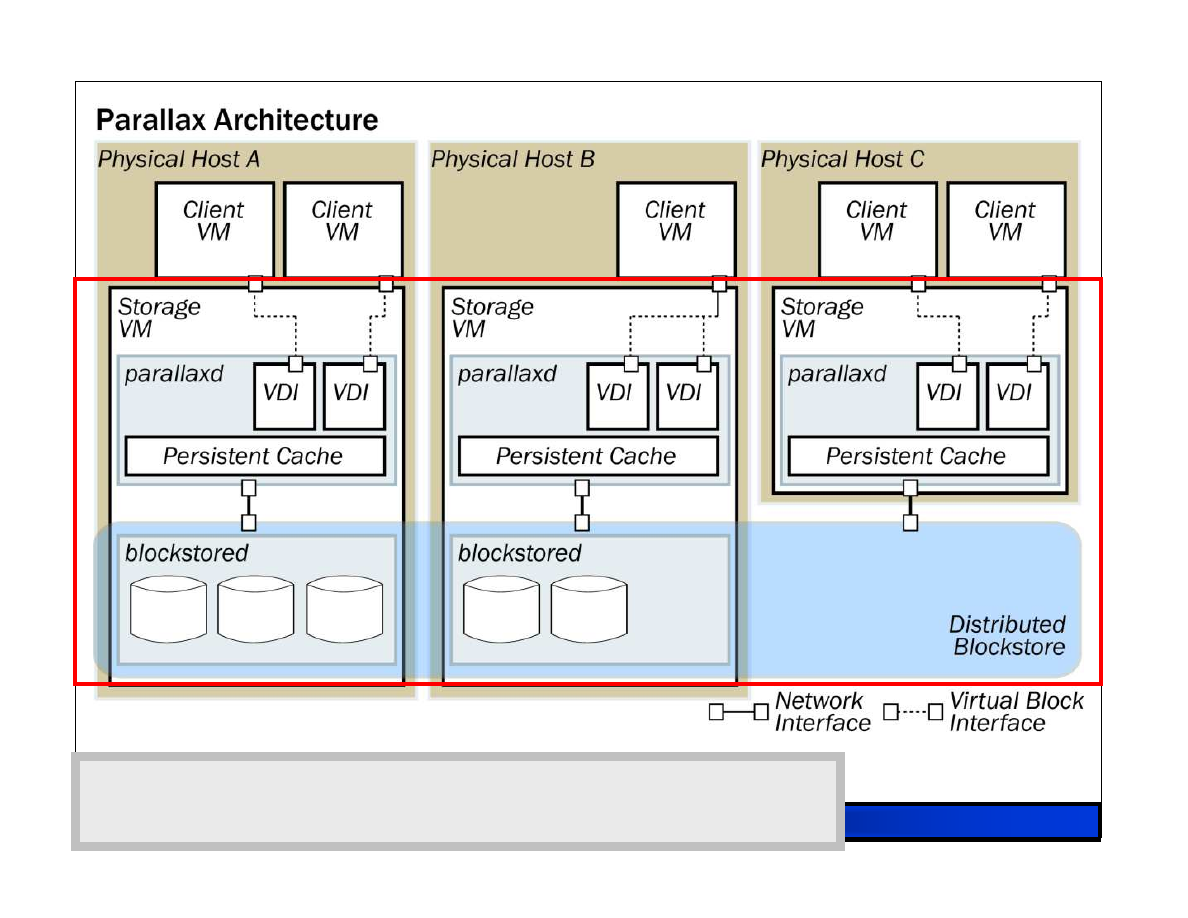
RHUL 23/02/07
79
Storage VMs aggregate to form a storage service. A
single administrative role manages filers, disks, drivers, etc.

RHUL 23/02/07
80
#3. Taint
#3. Taint
#3. Taint
#3. Taint----based protection
based protection
based protection
based protection
A generalized attack vector on desktops is the
eventual execution of downloaded code.
Idea: What if we prevented downloaded data from
ever executing?
Not just devices: Memory + CPU as well.
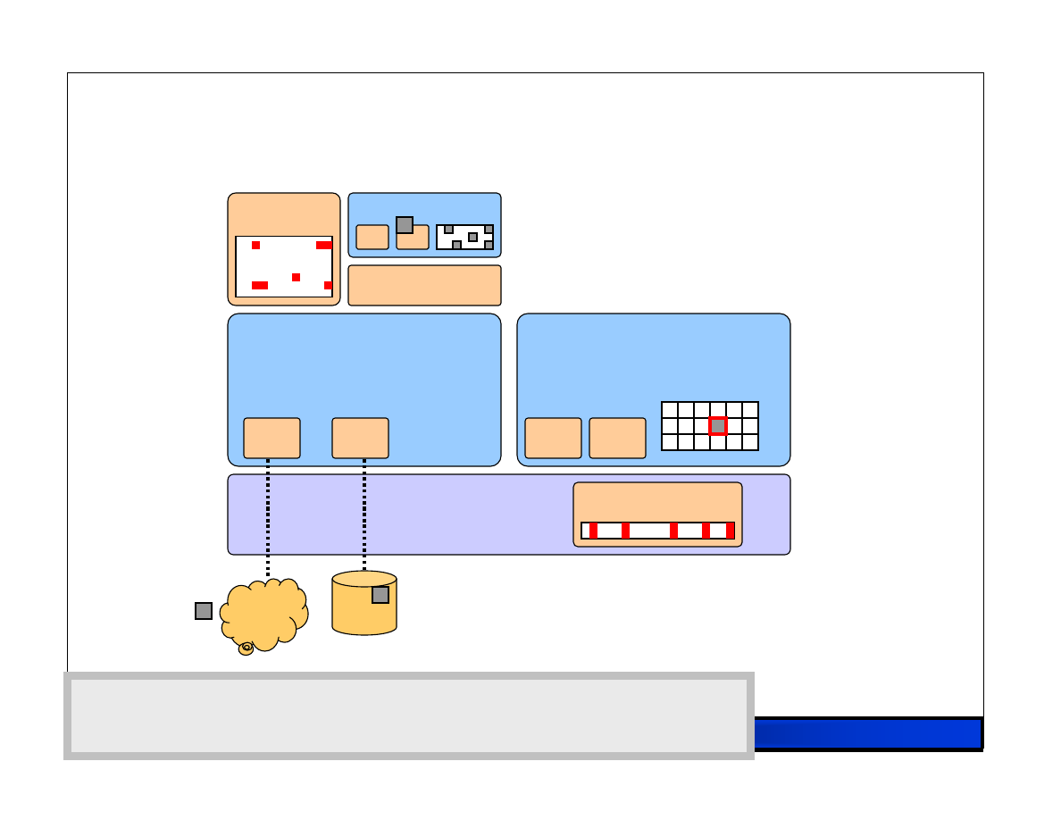
RHUL 23/02/07
81
V2E : Taint tracking
VMM
Control VM
DD
Disk
Net
ND
Protected VM
VN
VD
I/O Taint
Taint Pagemap
1. Inbound pages are marked as tainted. Fine-grained taint
Details in extension, page-granularity bitmap in VMM.
2. VM traps on access to a tainted page. Tainted pages
Marked not-present. Throw VM to emulation.
Qemu*
Protected VM
VN
VD
3. VM runs in emulation, tracking tainted data. Qemu
microcode modified to reflect tainting across data movement.
4. Taint markings are propagated to disk. Disk extension
marks tainted data, and re-taints memory on read.
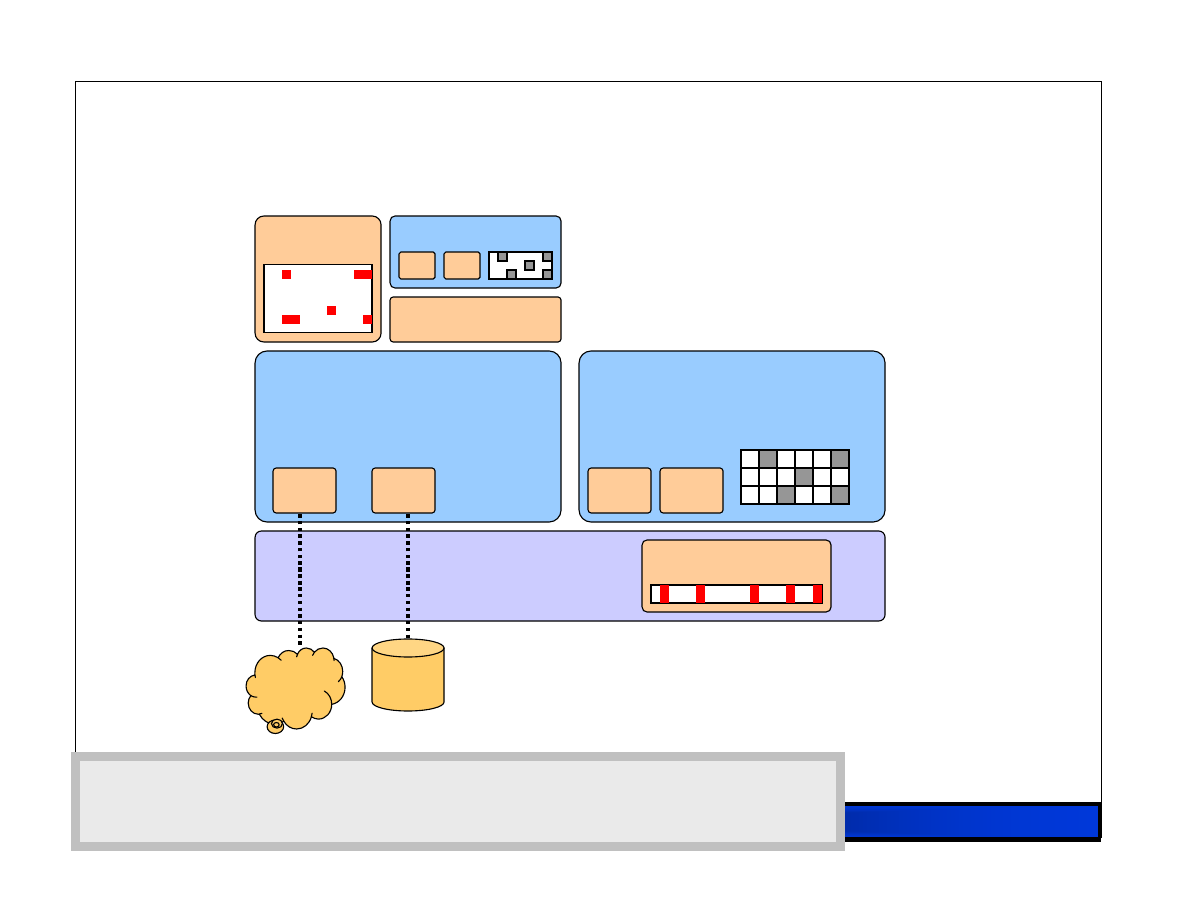
RHUL 23/02/07
82
V2E : Taint tracking
VMM
Control VM
DD
Disk
Net
ND
I/O Taint
Taint Pagemap
1. Inbound pages are marked as tainted. Fine-grained taint
Details in extension, page-granularity bitmap in VMM.
2. VM traps on access to a tainted page. Tainted pages
Marked not-present. Throw VM to emulation.
Qemu*
3. VM runs in emulation, tracking tainted data. Qemu
microcode modified to reflect tainting across data movement.
4. Taint markings are propagated to disk. Disk extension
marks tainted data, and re-taints memory on read.
Protected VM
VN
VD
Protected VM
VN
VD

RHUL 23/02/07
83

RHUL 23/02/07
84
Xen 3.x Roadmap
Xen 3.x Roadmap
Xen 3.x Roadmap
Xen 3.x Roadmap
Continued improved of full-virtualization
– HVM (VT/AMD-V) optimizations
– DMA protection of Xen, dom0
Off-box management API + tools
Performance tuning and optimization
– Less reliance on manual configuration
Better NUMA, Virtual Framebuffer, etc
Smart I/O enhancements
“XenSE” : Open Trusted Computing

RHUL 23/02/07
85

RHUL 23/02/07
86
Xen has the potential to become the
“trustworthy” computing solution:
– Open source
– Small size (< ~100K lines of code 3.x)
– Easy to add isolated security services
– High performance implementation
– Runs existing application software
– SRT scheduling and hard resource partitioning
gives performance predictability
Xen: The Road to Security
Xen: The Road to Security
Xen: The Road to Security
Xen: The Road to Security

RHUL 23/02/07
87
Xen: Security Enhanced
Xen: Security Enhanced
Xen: Security Enhanced
Xen: Security Enhanced
XenSE is about building a secure computing
platform around Xen
Open community effort:
– All design and implementation done in public
domain (mailing lists, source repositories)
– Buy-in from government (NSA, GCHQ, EU),
industry (IBM, HP, Intel, AMD) and academia
– Lots to do (targeting 4.0 timescale)
Ongoing since mid 2005…

RHUL 23/02/07
88
Security Requirements
Security Requirements
Security Requirements
Security Requirements
Standard model built around:
– a small ‘separation kernel’,
– mandatory access control, and
– a set of validated security policies
Modern technology also enables trust
– SRT (TPMs), DRT (SMX & Presidio)
Experience shows we also need:
– User Experience
• Incremental benefit, high performance, convenience
– Quality of Service
• Predictable partitioning and performance
• Defense against DOS attacks

RHUL 23/02/07
89
Availability
Availability
Availability
Availability
Can capture quality of service and (to an extent)
user experience as availability
Doesn’t matter if system is ‘secure’ if you can’t
actually use it
☺
Key things are:
– predictability (temporal scheduling)
– fairness (spatial scheduling)
– robustness (non-crashability)

RHUL 23/02/07
90
Static and Dynamic Root of Trust
Static and Dynamic Root of Trust
Static and Dynamic Root of Trust
Static and Dynamic Root of Trust
Already have static (platform-level) root of trust
– attested boot using TPM, trusted grub
– security policy part of this (see later)
Forthcoming support for dynamic root of trust:
– skinit and use of DEV on AMD-V platforms today
– senter/NODMA for Intel LT pending
– (DEV/NODMA protects Xen from devices)
More positive use of TCG features than DRM ;-)

RHUL 23/02/07
91
XenSE
XenSE
XenSE
XenSE: Access Control
: Access Control
: Access Control
: Access Control
Need mandatory access control…
– Add MAC to Xen subjects / objects
– IBM-contributed “ACM” framework allows null or
sHype models
XSM (“Xen Security Modules”) from NSA planned
to extend/replace this
– supports both sHype and more traditional MLS
models (particularly Flask)
– policy is a module included in measurements => can
remote attest policy installed
– initial code available but needs review

RHUL 23/02/07
92
sHype
sHype
sHype
sHype: Goals
: Goals
: Goals
: Goals
Goals derived from requirements of commercial
environments
High-assurance VMMs attempt to control all information
flows
sHype controls explicit information flows
– Memory sharing, event channel messages, virtual disks
sHype doesn’t attempt to control all covert channels
– Processor usage, error messages, memory allocation

RHUL 23/02/07
93
sHype
sHype
sHype
sHype: Design Basics
: Design Basics
: Design Basics
: Design Basics
sHype uses built-in VM separation
TPM attestation allows hypervisor and VMs to prove
their integrity at runtime to remote systems
Authorizes access to resources only upon initial access
and after policy changes
– Low performance overhead
Enforces formal policies
– Basis for defenses against DoS through resource policies
– Supports service level agreements (SLA)

RHUL 23/02/07
94
sHype
sHype
sHype
sHype: Policy Enforcement
: Policy Enforcement
: Policy Enforcement
: Policy Enforcement
Policy enforcement separated from access
control policy, similarly to the Flask / SELinux
architecture.
Security hooks embedded in core hypervisor
Hooks query access control module (ACM) and
enforce decisions
Decisions cached until policy changes
Trusted policy management VM manages ACM
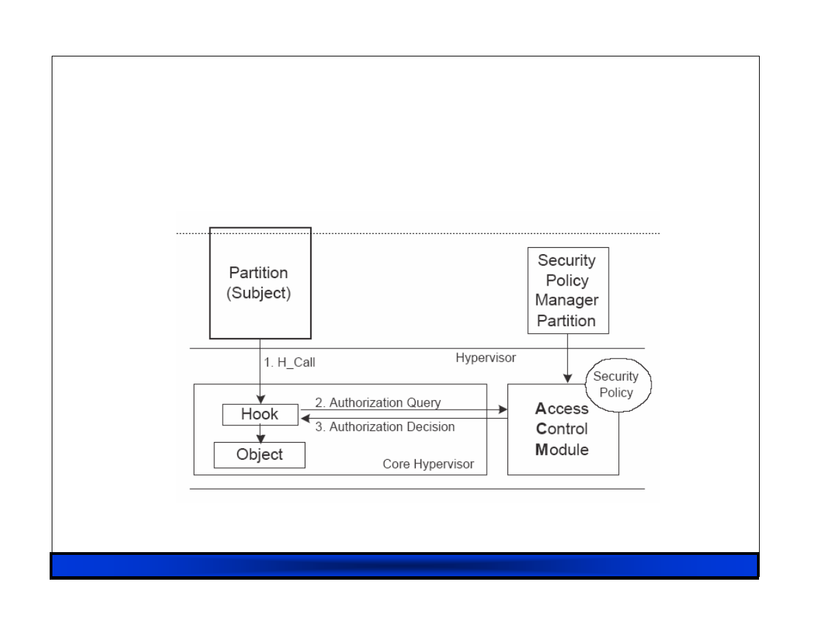
RHUL 23/02/07
95
sHype
sHype
sHype
sHype: Reference Monitor
: Reference Monitor
: Reference Monitor
: Reference Monitor

RHUL 23/02/07
96
sHype
sHype
sHype
sHype: Policy Changes
: Policy Changes
: Policy Changes
: Policy Changes
Updates ACM caches
Revokes event channels and shared memory
regions that are currently in use and are no
longer authorized
– Users of event channels receive errors, which
must be handled anyway
– Users of shared memory (e.g. device drivers)
receive memory error
– sHype may soon inform VM when memory is
revoked, to allow graceful shutdown

RHUL 23/02/07
97
sHype
sHype
sHype
sHype: Performance
: Performance
: Performance
: Performance
10 transfers of 10
8
disk blocks from Dom0 to
DomU
– dd if=/dev/hda7 of=/dev/null
count=10000000
No perceivable overhead, took 1196-1198
seconds
Grant-table (shared memory permissions) hook
invoked 12*10
6
times

RHUL 23/02/07
98
XenSE: Minimizing the TCB
XenSE: Minimizing the TCB
XenSE: Minimizing the TCB
XenSE: Minimizing the TCB
Current (2.0/3.0) TCB is too large:
– Xen, Dom0 kernel, Dom0 root, Network…
– Great for convenience but bad for security
Minimizing the TCB involves:
– Reviewing the Domain «-» Xen interface
– Adding fine-grained access control
– Refactoring Domain0:
• Decomposing functions into isolated components
• Involves support for ‘lightweight domains’
• Integration with trusted boot + attestation
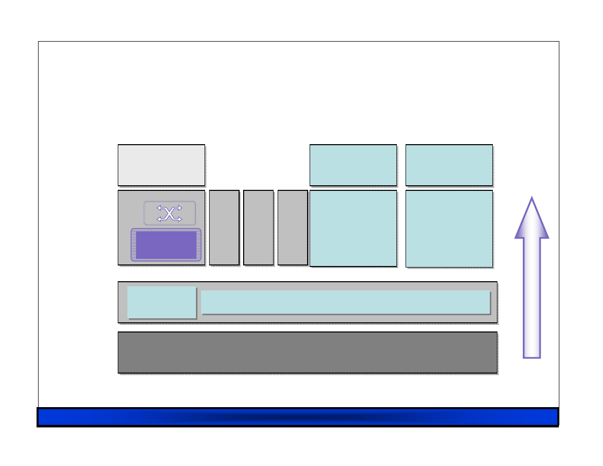
RHUL 23/02/07
99
Hardware
Hardware
XenSE Architecture
XenSE Architecture
XenSE Architecture
XenSE Architecture
Xen Control
Software
Xen Control
Software
Guest OS
(e.g.: Linux)
Guest OS
(e.g.: Linux)
User
Software
User
Software
Guest OS
(e.g.: Windows)
Guest OS
(e.g.: Windows)
User
Software
User
Software
Xen Control
Interface
Xen Control
Interface
Virtualized Hardware
Virtualized Hardware
Security
Manager
F
e
fa
c
to
re
d
P
ri
v
il
e
g
e
d
C
o
n
tr
o
l
D
o
m
a
in
M
A
C
T
P
M
IO
D
om
ai
n
S
er
vi
ce
D
o
m
ai
n
S
er
vi
ce
D
o
m
ai
n
A
tt
e
s
ta
ti
o
n
&
T
ru
s
t

RHUL 23/02/07
100
XenSE: Device Security
XenSE: Device Security
XenSE: Device Security
XenSE: Device Security
Recall: Availability a key part of security
Currently device drivers (and devices) major
cause of instability in OSes
Device security requires:
– Full implementation of safe hardware interface (w/
IOMMU or VT-d)
– Scheduler support for multiple DD domains
– Restartability, reconfigurability, attestation
– (possibly) support for secure I/O path

RHUL 23/02/07
101
XenSE: Non
XenSE: Non
XenSE: Non
XenSE: Non----Issues
Issues
Issues
Issues
Aiming for agile open design process and “code
rules” implementation
NOT currently focusing on:
– Standardization,
– Policy development,
– Digital Rights Management,
– Formal methods, or
– Evaluation – although will endeavor to make
XenSE “evaluable”.

RHUL 23/02/07
102
XenSE: Summary
XenSE: Summary
XenSE: Summary
XenSE: Summary
Community effort to build a (the first?)
successful trusted computing platform
Aiming to support wide range of uses:
– Firewall/IDS domains
– Virtual Private Machines (VPMs)
– Conventional MLS systems
Huge potential market for products
Want input from as many people, organizations
and interests as possible.

Thanks!
Thanks!
Thanks!
Thanks!

Next generation of hardware platforms
Stéphane Lo Presti
Royal Holloway, University of London
Stephane.Lo-Presti@rhul.ac.uk

www.opentc.net
2 April 2007
2
Introduction (1)
• Hardware-based solutions to security problems have
advantages that counteract software vulnerabilities:
– Hardware memory space is more tightly controlled and
defined.
– Hardware exists below the operating system (OS), so its
overall attack surface is reduced.
– Hardware is naturally less flexible than software in terms
of ease of modification.
• Following the TCG initiative, the general ideas of the
semiconductor industry are:
– To modify the architecture so as to improve its security
using the Trusted Computing features.
– To facilitate and enhance implementation of security
mechanisms in addition to or on top of the hardware.

www.opentc.net
2 April 2007
3
Introduction (2)
• Example of hardware attacks:
– On-chip probing, Focused Ion Beam;
– Removal or substitution attacks;
– Side-channel attacks (power, timing, electromagnetic
analysis);
– Board-level inter-chip bus write attacks on RAM or FLASH
memories whilst the System-on-Chip (SoC) is powered;
– Fault attacks (glitch, light, laser) relying on physical
disturbance to introduce faults in the software execution.
• Most new hardware platforms add support for
virtualisation and secure interfacing with the TPM.
• Some platforms use platform-specific TCG specifications:
– Example: PC-specific for Intel LaGrande and AMD-V.

www.opentc.net
2 April 2007
4
Introduction (3)
• We will look at the hardware changes introduced by the
main semiconductor vendors:
– Intel LaGrande Technology;
– ARM TrustZone;
– AMD-V.
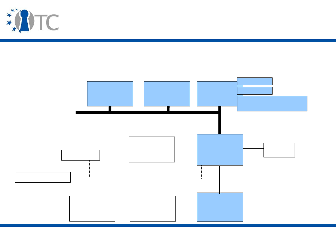
www.opentc.net
2 April 2007
5
A Brief Introduction to Hardware
Platforms (1)
• A Hardware platform is a complex system combining
numerous features. The Intel x86 architecture (IA-32)
looks like this:
CPU
Memory
Controller
Hub (MCH)
I/O
Controller
Hub (ICH)
RAM
USB
Controller
Keyboard
and Mouse
Graphics
Adapter
Front Side Bus (FSB)
Hub link
BIOS Boot Block
Parallel Port
Low Pin Count (LPC) bus
...
registers
caches
Memory Management
Unit (MMU)
CPU
CPU

www.opentc.net
2 April 2007
6
A Brief Introduction to Hardware
Platforms (2)
•
Registers
store pieces of information accessed
frequently or needed rapidly, and have various roles
(processor configuration, instruction operands).
•
Memory caches
are used to reduce the number of
accesses to memory.
– Caches are generally divided into instruction and data
caches.
– Caches are organised as tables, indicating the memory
address, a cache index and the instruction/data, and are
managed on the basis of the frequency of use of each
entry (or line, or block).
– There are different levels of cache: Level 1 (L1) is smaller
and faster than Level 2 (L2).

www.opentc.net
2 April 2007
7
A Brief Introduction to Hardware
Platforms (3)
• Memory addressing necessitates address conversions
done by the Memory Management Unit (MMU).
–
Segmentation
translates a logical address into a linear
address, which can be a physical address if paging is not
used (real mode of x86 processors);
–
Paging
translates a linear address into a physical address
(protected mode of x86 processors);
• Some pages are stored in memory, while others are moved to
a disk device (swap file).
– The entity controlling these conversions can provide
virtual memory to applications and it enforces memory
separation between the applications.
– The last few address conversions are cached in the
Translation Lookaside Buffer (TLB) .

www.opentc.net
2 April 2007
8
A Brief Introduction to Hardware
Platforms (4)
– The Global Descriptor Table (GDT) defines the properties
of the various memory areas/segments (size, read/write,
access privileges).
• The Local Descriptor Table (LDT) lists segments specific to
applications.
– Direct Memory Access (DMA) allows certain hardware
components to launch data transfers that are not
monitored by the CPU. The CPU initiates the requested
transfer by setting up a DMA channel (possibly through a
physical bus) and is notified by an interrupt when the
transfer is complete.
• This is done for efficiency reasons (graphics for games,
network for servers).
• But it is dangerous, as the CPU is bypassed during transfer
(device drivers).

www.opentc.net
2 April 2007
9
A Brief Introduction to Hardware
Platforms (5)
– Memory-mapped Input/Output (I/O) enables devices to be
accessed by reading and writing from a particular memory
space.
• This is how the TPM is accessed in the PC-Specific TPM
specification.
• Interrupts are hardware signals used to indicate various
kinds of events (hardware, software, processor
exceptions).
– They are handled by interrupt handler whose address is
stored in the Interrupt Descriptor Table (IDT).
• System Management Interrupt (SMI) is a special mode of
the processor, used for low-level events (temperature,
leds). It is managed by the STM (SMI Transfer Module).
– It can be used to bypass normal functioning (and the
Operating System).
•
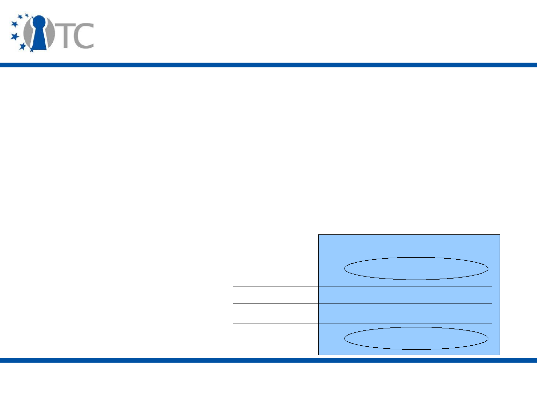
www.opentc.net
2 April 2007
10
A Brief Introduction to Hardware
Platforms (6)
• Rings are a privilege levels of execution implemented in
the processor to separate the Operating System (OS)
from the services and applications that it manages.
• There are four ring levels numbered 0 to 3.
– Current OSs only use ring 0 (supervisor or kernel mode)
and ring 3 (user mode).
• Each program in a ring can access the resources
(control, memory) of the programs running in rings
above it.
Processor
Ring 3
Ring 2
Ring 1
Ring 0
Applications
Operating System

www.opentc.net
2 April 2007
11
A Brief Introduction to Hardware
Platforms (7)
• AMD uses a different hardware platform where the
Memory Controller Hub (MCH) is in the CPU, and the
Front Side Bus (FSB) is replaced by the HyperTransport
bus (which is simpler and faster).

www.opentc.net
2 April 2007
12
A Brief Review of Virtualisation
Technologies (1)
• Virtualisation is the abstraction of hardware components
using software components that provide a subset of the
hardware's functionality.
• There are various virtualisation techniques:
– Via an Operating System, by grouping processes into
resource containers. Example: the Virtuoso system.
– Full virtualisation of the hardware. Examples: Vmware and
Virtual PC.
– Para-virtualisation, where the abstraction of the hardware
modifies slightly the hardware functionality. Examples:
Xen and L4Linux.
• Virtualisation is different from emulation, which
emulates a certain kind of hardware platform on top of a
different hardware platform.

www.opentc.net
2 April 2007
13
A Brief Review of Virtualisation
Technologies (2)
• A Virtual Machine Monitor (VMM) or a hypervisor
manages Virtual Machines (VMs) in order to ensure that
they execute in parallel as if they were running on the
hardware and in isolation from each other.
– A VMM generally encapsulates a host OS, while a
hypervisor is a smaller software component.
– A VMM has to execute at a higher level of privilege than its
VMs in order to keep control of the platform and enforce
policies.
• Currently, VMs run in ring 1, while the VMM is in ring 0.

www.opentc.net
2 April 2007
14
A Brief Review of Virtualisation
Technologies (3)
• A VM can be a full-blown OS or a small application.
• Each VM can run as if it had the whole hardware
platform for itself, but it actually only communicates
with virtual devices.
• Virtualisation also provides additional properties:
– The VM can be stored and moved between platforms.
– Isolation can be used to provide a transient execution
environment where the user does not need to worry about
security, but information may be lost after VM shutdown.
– The computer can become a virtual network of VMs.

www.opentc.net
2 April 2007
15
A Brief Review of Virtualisation
Technologies (4)
• As seen last week (Steve Hand), VMMs do some tricks in
order to ensure isolation and correct functioning, but
they can still be bypassed in current hardware platforms
(e.g. via Direct Memory Access/DMA or System
Management Interrupt/SMI).
– Efficiency is paramount for virtualisation technologies.
– Security is also important, as the VMM is in charge of
enforcing a policy.
– New hardware platforms provide support for some of the
tricks implemented by VMMs (e.g. Shadow Page Tables) .

www.opentc.net
2 April 2007
16
Dynamic Root of Trust for Measurement
(DRTM) (1)
• A Dynamic Root of Trust for Measurement (DRTM, or
Dynamic CRTM) is a Root of Trust for Measurement (RTM)
that can be started at an arbitrary point in time during
the platform execution in order to measure a designated
software component (e.g. a VMM).
• The software executing before the DRTM cannot
compromise the process of starting the DRTM.
• The DRTM requires new CPU instructions to put the
hardware platform in a known state.

www.opentc.net
2 April 2007
17
Dynamic Root of Trust for Measurement
(DRTM) (2)
• In the PC-Specific TCG specification, locality 4 is reserved
for the Trusted Hardware (DRTM) to access the TPM.
• Dynamic PCRs are PCR[17] to PCR[22], and they are used
for measuring the software components started after the
DRTM (VMM and VMs).
• The code to be executed is sent to the TPM to be
measured, and the resulting value used to update one of
the first dynamic PCRs, which are accessible only when in
the DRTM initialisation state and only by the CPU.
• With a DRTM, if trust is lost at one point, a chain of trust
can be started without rebooting the platform.
– It is usually a shorter chain that the one generated at boot
time, as there are less components involved.

www.opentc.net
2 April 2007
18
Intel LaGrande (1)
• LaGrande Technology (LT) is now known as Trusted
Execution Technology (Safer Computing initiative).
• Security mechanisms for the new Intel Architecture are
added to the current ones:
–
Protected mode
is a mode of execution of the processor
that supports virtual memory via paging, implements
efficient task switching (in hardware), and provides rings.
–
Rings
are privilege levels of execution. The Operating
System (supervisor) executes in ring 0 and applications
(user) run in ring 3.
–
Paging
enables pages of memory to be allocated to
programs, providing domain separation.

www.opentc.net
2 April 2007
19
Intel LaGrande (2)
• LT complements the Intel Virtualization Technology (VT-
d).
• LT is implemented as hardware extensions to the
processor, the chipset and other platform components.
• LT is designed to “help protect against software-based
attacks” and “increase the confidentiality and integrity
of sensitive information from software-based attacks,
protect sensitive information without compromising the
usability of the platform, and deliver increased security
in platform-level solutions through measurement and
protection capabilities.”
• A TPM v1.2 is required.

www.opentc.net
2 April 2007
20
Intel LaGrande (3)
• LT's design principles include:
– Backward compatibility
• Legacy code must be able to run as in the old Intel Architecture
(IA-32).
• Software not concerned with security runs unaffected.
• The Intel architecture has been modified significantly since its
beginning and backward compatibility over the years led to the
accumulation of constraints (support for old code from multiple
vendors in a long boot sequence, Master Boot Record stored on
the hard disk with little protection) that could break security.
– A “late launch” (Dynamic Root of Trust for Measurement, DRTM)
helps solve this problem.
– Opt-in (LT disabled by default)
– Complex systems
• Multi-core, multi-processor
• Abstract view of the architecture hides the details!

www.opentc.net
2 April 2007
21
Intel LaGrande (4)
• LT principal aim is the protection of data (memory) and
main peripherals (keyboard, mouse, display).
• LT is based on the following security principles from [J.
Saltzer and M. Schroeder, Proceedings of the IEEE,
September 1975]:
– Least privilege: access to resources should be limited to a
designated set of entities, with only the necessary access
rights.
– Economy of mechanism: privileged mechanisms should be
as small as possible, so that they can be easily verified.
– Complete mediation: all resource accesses must be
explicitly authorised.
• All entities accessing resources must be unambiguously
identified.

www.opentc.net
2 April 2007
22
Intel LaGrande (5)
– Open design: the protection of the system should not rely
on keeping part of its design secret.
• But some secrets are kept to protect Intellectual Property.
– Separation of privilege: more than one mechanism should
be used to protect the system, i.e. the various hardware
and software components should have well-defined and
separated roles.
• Policy decision and enforcement are usually separated.
• Defence in depth uses multiple techniques to help mitigate
the risk of one component of the defence being compromised
or circumvented.
– Least common mechanism: mechanisms should share the
minimum amount of code.

www.opentc.net
2 April 2007
23
Intel LaGrande (6)
– Psychological acceptability: the technology should be easy
to understand and use for the user.
• Security gets in the way of functionality.
• If the protection mechanisms are not acceptable, a user will
attempt to circumvent them.
• LT is composed of three main architectural components:
– Standard partition;
– Protected partition;
– Measured VMM (MVMM).

www.opentc.net
2 April 2007
24
LT partitions (1)
• The Standard partition is identical to today's Intel
Architecture (IA-32) environment (no LT).
– Software components unconcerned with security have
somewhere to execute unaffected and unmodified.
– Protection can still be provided by accessing the protected
partition through the MVMM (if it is running).

www.opentc.net
2 April 2007
25
LT partitions (2)
• The Protected partition:
– It is based on a kernel which implements a rich (i.e. a full
Operating System with process, memory and I/O
management, multi-tasking, etc.) or a limited set of
services.
– Protected software execution ensures that the software
cannot be tampered with by software executing in either
the standard or protected partition.

www.opentc.net
2 April 2007
26
LT partitions (3)
• Partition communication is managed by the MVMM
which makes policy decisions and enforces them by
using the LT features.
• Various mechanisms can be implemented by the MVMM
for partition communication: Inter-Process
Communication (IPC), Remote Procedure Call (RPC), or
shared buffer zone.
– Or use standard services, such as network or files.
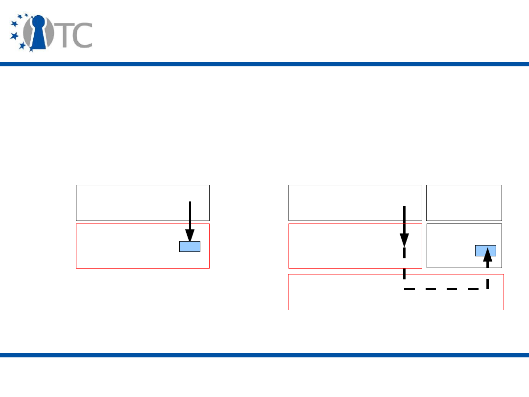
www.opentc.net
2 April 2007
27
LT partitions (4)
• Security can be made implicit (notably in the standard
partition) through service call redirection to a security
kernel.
– This facilitates separation of concerns as applications do
not need to know what specific service is used.
Applications
Operating
System (OS)
ring 3D
ring 0D
VMM
ring 0P
Without MVMM
With MVMM
Kernel
ring 3
ring 0
Applications
Operating
System (OS)

www.opentc.net
2 April 2007
28
LT MVMM
• The central component of LT is the Measured VMM
(MVMM, or Domain manager).
• The MVMM is in charge of:
– Memory arbitration;
– Resource assignment;
– Communication channels;
– Partition lifecycle.
• The VMM has its own memory and can be launched by
the BIOS, the OS loader or the OS (DRTM).
• The VMs can be standard or protected.

www.opentc.net
2 April 2007
29
Authenticated Code (AC)
• MVMM functionality is supported by Authenticated Code
(AC), firmware code which is signed by the chipset
manufacturer and is executed in its own hardware-
protected area. An AC contains a header section that
indicates information used for its verification (e.g. public
signature verification key).
• Authenticated Code includes SINIT and SCLEAN which
perform various tasks:
– SINIT initialises the hardware configuration and locks the
memory configuration to prevent certain attacks (memory
folding);
– SCLEAN ensures that secrets are not left visible after
operations.

www.opentc.net
2 April 2007
30
SMX mode
• SMX is the security mode of the Intel processor.
• The SMX interface includes the following functions:
– Measured launch of the VMM;
– Mechanisms to ensure the above measurement is
protected and stored in a secure location;
– Protection mechanisms that allow the VMM to control
attempts to modify the VMM.

www.opentc.net
2 April 2007
31
VMX mode (1)
• VMX is the virtualisation mode of the Intel processor:
– The CPU is in one of two states:
•
VMX root operation
when MVMM is in control (and only then);
•
VMX operation
when guest VM is in control (and only then);
– VMX operation stops when a VM requests a resource it
does not control, a VMEXIT event is generated and the
CPU switches to VMX root operation where the MVMM
decides whether or not to perform the resource access
(denying the access is also called a “de-privilege”); control
is returned to the VM by generating a VMRESUME event.

www.opentc.net
2 April 2007
32
VMX mode (2)
• Control mechanisms (Global Descriptor Table/GDT ,
Interrupt Descriptor Table/IDT) are directly available to
the VMM and are virtualised to guest VMs.
• A VM Control Structure (VMCS) is used to store
information about the VMM (e.g. which events and
operations cause a VMEXIT) and its VMs (e.g. execution
state, cause of most recent VMEXIT). It can only be read
and written by the VMM.
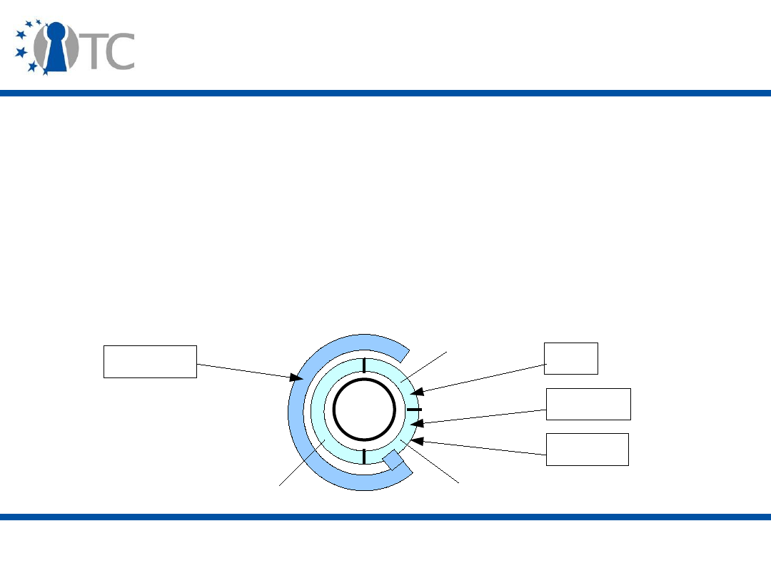
www.opentc.net
2 April 2007
33
Page protection
• The MVMM is in total control of policy decision and
enforcement (control registers).
• DMA access is checked with a NoDMA table that is
maintained by the MVMM.
– Special case: display adapter with specific pages and table,
such that only one guest VM has access to it at a time.
• Interrupts are checked by the SMI Transfer Module (STM) in
cooperation with the MVMM.
Physical
Page
Paging
NoDMA
STM
SVMM
Software
Page access
SMI
Devices
Display
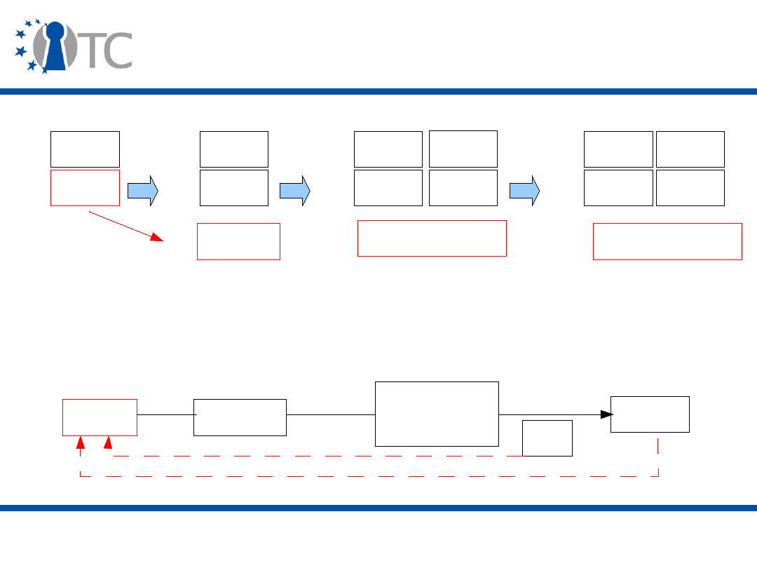
www.opentc.net
2 April 2007
34
VMM launch
Apps
OS
3
0
Apps
OS
3D
0D
Apps
OS
3D
0D
Apps
OS
3D
0D
VMM
VMM
VMM
0P
0P
0P
Apps
OS
• The goal is to measure the VMM. This process follows a
controlled sequence of operations:
Chipset
TPM
SMX
instruction
VMM
measures
AC
measurements
Locality 4

www.opentc.net
2 April 2007
35
GETSEC [SENTER] (1)
• During the execution of GETSEC [SENTER], the Initiating
Logical Processor (ILP) accesses the TPM via PC-Specific
commands only available from locality 4 and memory-
mapped.
– Example of commands: TPM.HASH.START,
TPM.HASH.DATA, TPM.HASH.END.
• The AC module and MVMM are loaded in memory by the
launching environment, and then the GETSEC [SENTER]
instruction is invoked:
– Launched by a ring 0 process (BIOS, OS);
– The Initiating Logical Processor (ILP, must be the Bootstrap
processor) takes control of the chipset while other
processors are put to sleep;
– All events are disabled until instruction is completed.

www.opentc.net
2 April 2007
36
GETSEC [SENTER] (2)
• The SINIT AC is measured, the resulting value used to
update PCR[17], it is launched from locality 3, and:
– It tests the hardware configuration;
– It validates and launches the STM (Secure Message
Interrupt/SMI transfer Monitor);
– It enables the NoDMA functionality;
– It measures the SCLEAN AC into PCR[17] or Non-Volatile
(NV) memory;
• SCLEAN erases secrets in case of hardware or software
failures;
– It measures the MVMM, performs basic checks on its page
table and, if successful, adds the MVMM pages to the
NoDMA table and measures them; it then stores the
measurement in PCR[18], and launches the MVMM.

www.opentc.net
2 April 2007
37
GETSEC [SENTER] (3)
• The MVMM then re-enables the interrupts and SMI
events, and wakes up the processors that were put to
sleep.
• Errors are indicated by an LT-shutdown message which:
– Saves the error code;
– Initiates a platform reset;
– Masks LT-related events and information.

www.opentc.net
2 April 2007
38
GETSEC [SENTER] (4)
• MVMM terminates itself by launching the GETSEC
[SEXIT] instruction.
– No need for an AC at the moment, as the MVMM is
considered secure (because of its small size and its
specific functionality), but an AC can be added in the
current LT architecture.
– When the MVMM terminates, it clears all secured
memories and makes sure all components are ready to
function in a non-VMM environment.

www.opentc.net
2 April 2007
39
VMMs
• Other VMM services include:
– VM life-cycle and scheduling;
– Kernel features.
• VMMs may be constructed in various ways, depending
on the architecture implemented.
– Example: NGSCB isolation kernel, Xen.
www.opentc.net
2 April 2007
40
Protected input and output (1)
• LT provides Trusted Channels, but not Trusted Paths.
– Paths require display to add indicators visible to the user,
indicators can be sealed to the MVMM.
• Channel endpoints are the device and a device driver.
• This functionality may require new input devices with
cryptographic capabilities for highest security.
• The application is responsible for creating the trusted
path.
Device
LT
Application
Trusted path
Trusted channel

www.opentc.net
2 April 2007
41
Protected input and output (2)
• LT supports two kinds of trusted channels:
– Physical;
– Cryptographic.
• Devices supported by default are:
– USB;
– Display;
– Keyboard and Mouse (Trusted Mobile Keyboard Controller).

www.opentc.net
2 April 2007
42
Protected input and output (3)
• The output channel (graphics) is a special case due to:
– Huge requirements in terms of performance;
– Numerous cards and chips.
• Integrated graphics can use hardware channels.
• Cryptographic key pair used to authenticate display
adapter to channel driver.
– Privacy problem: requires a change to the PCI-e bus, i.e.
Trusted Configuration Space (TCS) so that graphics driver
obtains and uses the public key to create trusted channel.

www.opentc.net
2 April 2007
43
Protected input and output (4)
• One proposed model for a trusted graphics engine is the
Trusted Sprite Model:
– Builds a
Trusted Surface
(main display) stored in a specific
secure memory space;
– The Trusted Surface is accessed through the MVMM or a
designated secure display driver;
– The Trusted Surface overlays the entire main display
surface;
– Any other surface is only visible if the corresponding portion
of the Trusted Surface is set transparent (the Trusted
Surface has the highest Z-order, where Z indicates the
stacking order of surfaces on the screen);
– The trusted sprite limits the graphics configuration;
– Any graphics configuration change implies reconstructing
the Trusted Surface after the change.
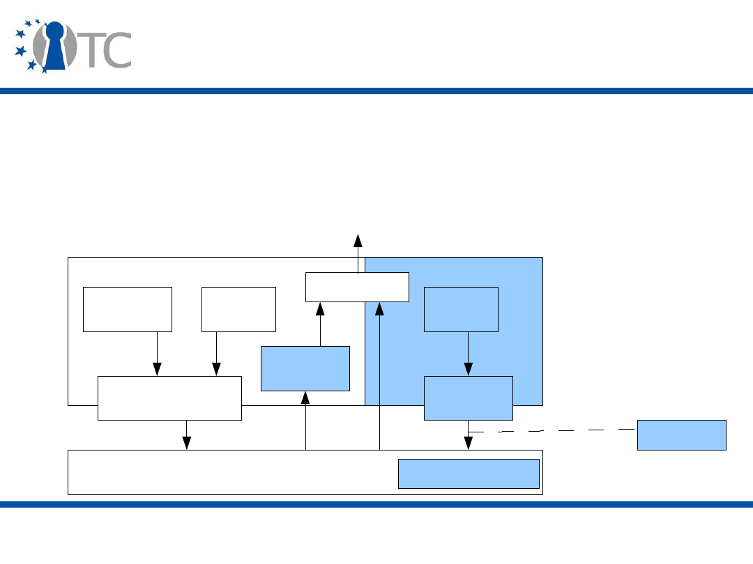
www.opentc.net
2 April 2007
44
Protected input and output (5)
• A non-spoofable panic mode screen (BSOD, Blue Screen
Of Death) is also provided by the Trusted Sprite Model.
• The Trusted Graphics Engine is organised as follows:
Memory Controller
Untrusted
Trusted
Multiplexer
Graphics
Engine
Display
Refresh
Graphics translation
table (GTT)
Trusted
GTT
Locked
Assets
Display
Refresh
NoDMA
Data
Address
Address
Trusted Surface
MVMM
Display

www.opentc.net
2 April 2007
45
LT and the TPM
• LT further uses the TPM to:
– Protect platform against hardware attacks that look for
secrets in memory;
– Provide support for SCLEAN's access control so that all
clean-up activity is not interrupted;
– Encrypt communications between CPU and TPM in a
transport session to protect confidentiality of exchanged
information on the Low Pin Count (LPC) bus;
• Information is still exchanged between CPU and memory on
the Front Side Bus (FSB) bus, but accessing the FSB is a more
expensive attack;
– Generates random numbers which can be used as
symmetric encryption keys for the MVMM;
– Seal secrets to the MVMM for secure applications.

www.opentc.net
2 April 2007
46
ARM TrustZone (1)
• ARM processors are mainly targeted at embedded
systems (smart phone, PDA, game console, Set Top
Box).
• These platforms have:
– Very limited resources, e.g. memory, processing power.
– Very specific requirements, e.g. power consumption,
performance, area.
• Furthermore they require complex trade-offs between
choice of components, functionalities and level of
protection against hardware and software attacks.

www.opentc.net
2 April 2007
47
ARM TrustZone (2)
• These platforms are usually less open than in the PC
world.
– User usually does not update the firmware.
– More hardware-specific systems are built (System-on-Chip,
SoC).
– Secure boot is easier to perform as the hardware has
secure storage available at the start of the boot.
• Traditionally, systems are partitioned with 2 CPUs where
one executes an open OS (Symbian, Windows, Palm)
and the other the security sensitive code (Real Time OS,
RTOS).
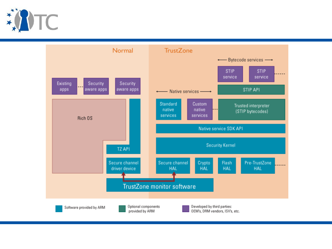
www.opentc.net
2 April 2007
48
ARM TrustZone (SW point of view)

www.opentc.net
2 April 2007
49
ARM TrustZone (3)
• TrustZone implements a single-CPU solution that adds:
– A secure permission domain which has access to security
functionalities (integrity verification, protected memory);
– A Monitor mode of operation which controls the separation
and switching between secure and non-secure worlds;
– An SMI (Secure Monitor Interrupt) instruction invoked by
Real Time OS to securely enter the Monitor mode;
– An
NS bit
in a coprocessor register and
S bit
in memory to
distinguish between secure and non-secure worlds.
• TrustZone's core functionalities are hardwired into the
processor core (System-on-Chip, SoC) and involve no
software.
• A new bus is used to communicate information between
the components of the secure world.

www.opentc.net
2 April 2007
50
ARM TrustZone (4)
• The Monitor is in charge of:
– Saving the context (registers, configuration settings) of
currently running non-secure processes;
– Switching to secure processes;
– Reciprocally saving and switching back to non-secure
mode.
• Caches and memory spaces are each separated into the
secure and the non-secure worlds (
S bit
).

www.opentc.net
2 April 2007
51
ARM TrustZone (5)
• The Real Time OS (RTOS) is still in charge of context
switches between non-secure processes.
• Processes can check an
NS bit
to determine the mode.
• Communication between secure and non-secure world is
done by message-passing. Addresses are passed to
communicate large amount of data.
• Trusted Logic's Security Module (Security Kernel)
software provides high level functionality, such as
cryptography, safe storage and integrity checking.
• The Trusted Interpreter provides protected transactions
(over-the-air upgrades) independently from the OS.
– Similar to SIMcard: code uses the STIP interface (bytecode)
and is executed in a sandbox.

www.opentc.net
2 April 2007
52
ARM TrustZone (6)
• Main HW components:
– TrustZone CPU;
– Secure on-chip boot ROM
(master key);
– On-chip NV or OTP
memory;
– Secure on-chip RAM;
– Resources (peripherals)
that can be configured to
allow access by trusted
applications.
• Main SW components:
– Security kernel;
– Native security services;
– Trusted interpreter;
– Trustzone APIs;
– Bootloader;
– Monitor.
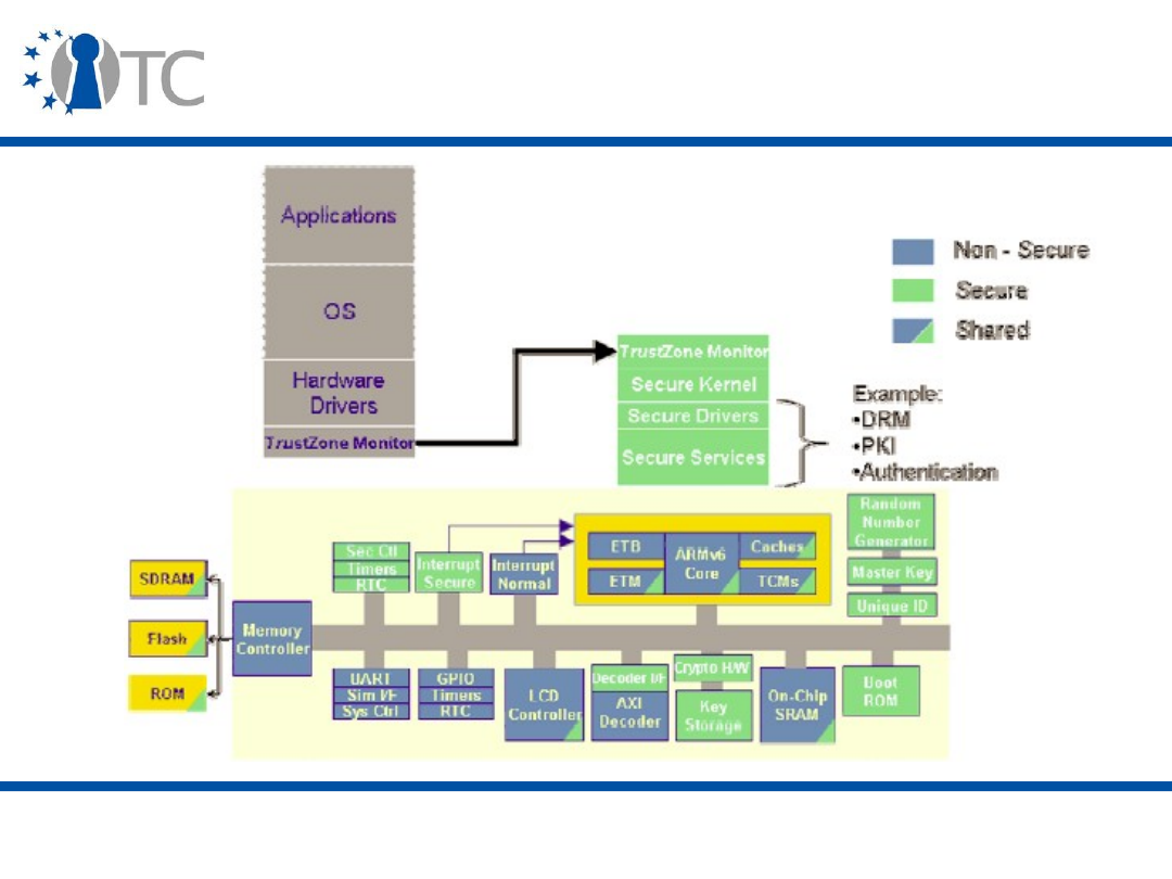
www.opentc.net
2 April 2007
53
ARM TrustZone (HW point of view)

www.opentc.net
2 April 2007
54
ARM TrustZone (7)
• TrustZone ensures the integrity of the OSs and enforces
policy between the various interrupt types.
• Furthermore it provides the facility to disable debugging
of the secure world.
• Backward compatibility is ensured through software
emulation (Security Kernel, i.e. Trusted Logic's Security
Module).
• Software Multicore makes use of a second processor
(ARM or other) dedicated to cryptography when it is
available.

www.opentc.net
2 April 2007
55
ARM TrustZone (8)
• TrustZone can be used to implement IMEI protection and
SIMlock via secure boot, secure storage and runtime
integrity checks.
• Other application examples include the prevention of
the rollback of car mileage reading in rental cars
(monotonic counter).

www.opentc.net
2 April 2007
56
AMD-V (1)
• AMD new architecture, called AMD-V, is built around two
activities:
– HW and I/O virtualisation (Pacifica)
• Special host mode for the VMM and guest mode for the VMs;
• VMRUN instruction to switch to host mode and start a VMM.
– Security enchancements (Presidio)
• Hardware-enforced privilege levels;
• Strong domain separation;
• I/O and device protection.
• AMD's framework works in conjunction with a TPM which
is assumed to be connected to the LPC bus (PC-
specific).

www.opentc.net
2 April 2007
57
AMD-V (2)
• Virtualisation and security extensions are combined to
provide an SVM (Secure Virtual Machine).
– No modifications to the x86 boot process are required, but
special hardware logic is added in the processor and
chipset.
• The Device Exclusion Vector (DEV) has the same role as
the NoDMA table in LT, i.e. to enable the VMM to control
Direct Memory Access (DMA). Devices are grouped in
domains which each have a DEV structure.
• A Global Interrupt Flag (GIF) is used to suspend
interrupts (GIF=0)

www.opentc.net
2 April 2007
58
AMD-V (3)
• The VMM controls the VMs by populating the Virtual
Machine Control Block (VMCB) which defines the
processor, memory and I/O operations authorised for
each VM.
• The VMCB is used to decide when to redirect a resource
access made by a VM in guest mode to the VMM (in host
mode). The VMM can then decide whether or not the
access is authorised.
• During mode switches, AMD-V checks that no
unexpected modifications occur. Part of the context of a
VM that is interrupted is stored to and restored from the
Virtual Machine Control Block (VMCB).
– Instructions VMLOAD and VMSAVE can be used to
respectively load and store the whole context.

www.opentc.net
2 April 2007
59
AMD-V (4)
• VMM and VMs communicate in a complex manner:
– The instruction VMMCALL enables a VM to
communicate with its VMM. For example, to ask for
more memory or disk space.
– The VMM can inject virtual interrupts that will be
caught by a VM.

www.opentc.net
2 April 2007
60
SKINIT (1)
• The SKINIT (Secure Kernel Initialisation) instruction is
the main addition to the AMD framework.
– It can be executed from an untrusted state (Dynamic Root
of Trust for Measurement, DRTM).
– Special hardware logic makes it unspoofable and
uninterruptable.
– Works in a multi-processor environment similarly to LT.

www.opentc.net
2 April 2007
61
SKINIT (2)
• SKINIT's operating sequence is the following:
– The launching environment loads the Secure Loader (SL)
and Secure Kernel (SK) into memory;
– SKINIT first puts the platform in a well-known hardware
configuration such that the SKINIT instruction is
guaranteed to be atomic (GIF=0), only one processor is
running, and no code modification is possible;
– SKINIT then verifies the signature of the Secure Loader
(SL) and that the SL satisfies the format of SL images; if
successful, the SL is measured using the TPM;
– SKINIT then executes SL in a separate memory space, with
the CPU in a non-paged mode and with registers set to
values based on the SL.

www.opentc.net
2 April 2007
62
SKINIT (3)
• At this point, the state of the platform is:
– The CPU is a known state not dependent on software
running before SKINIT and is about to start executing SL;
– The cryptographic hash of the SL is stored securely in the
TPM.
• The SL then establishes the DEV structures, measures and
launches the Secure Kernel (SK), i.e. the VMM.
• SKINIT ensures a clean state is restored if any step is aborted.

www.opentc.net
2 April 2007
63
Conclusion
• Trusted Computing goes beyond the TCG specifications:
– Hardware accommodates the required changes;
– Semiconductor companies build upon the TCG principles
and the TPM to improve platform security.
• This is a huge improvement that will change the
industry and its customers.
– The PC platform specification was getting old and limited.
• But there are a variety of improvements and platform
changes, some of which are targeted at the platform
vendors and some at the software industry.
– It is difficult to predict how all this is going to connect.
• Next: Trusted Computing Applications, part 1, Operating
Systems

www.opentc.net
2 April 2007
64
References (1)
• Computer platforms:
– John L. Hennessy and David A. Patterson. Computer
Architecture: A Quantitative Approach. Morgan Kaufmann
Publishers, 2003
– http://en.wikipedia.org/wiki/Computer_architecture
• Virtualisation technology:
– P. Barham et al. Xen and the Art of Virtualization. In
Proceedings of the nineteenth ACM symposium on
Operating systems principles (SOSP '03), 2003.
–
http://en.wikipedia.org/wiki/Virtualization_Technology
–
http://www.kernelthread.com/publications/virtualization/

www.opentc.net
2 April 2007
65
References (2)
• Intel LaGrande:
– David Grawrock. Intel Safer Computing. Intel Press, 2006.
–
http://www.intel.com/technology/security/
• ARM TrustZone:
http://www.arm.com/products/esd/trustzone_home.html
• AMD-V:
– Geoffrey Strongin. Trusted computing using AMD "Pacifica"
and "Presidio" secure virtual machine technology.
Information Security Technical Report, Volume 10, Issue 2,
2005, Pages 120-132.

www.opentc.net
2 April 2007
66
The information in this document is provided “as is”, and no guarantee or
warranty is given that the information is fit for any particular purpose.
The user thereof uses the information at its sole risk and liability.
The Open-TC project is co-financed by the EC.
If you need further information, please visit our website
www.opentc.net or contact the coordinator:
Technikon Forschungs- und Planungsgesellschaft mbH
Richard-Wagner-Strasse 7, 9500 Villach, AUSTRIA
Tel.
+
43 4242 23355 – 0
Fax.
+
43 4242 23355 – 77
Email coordination@opentc.net
Open_TC EC Contract No: IST-027635
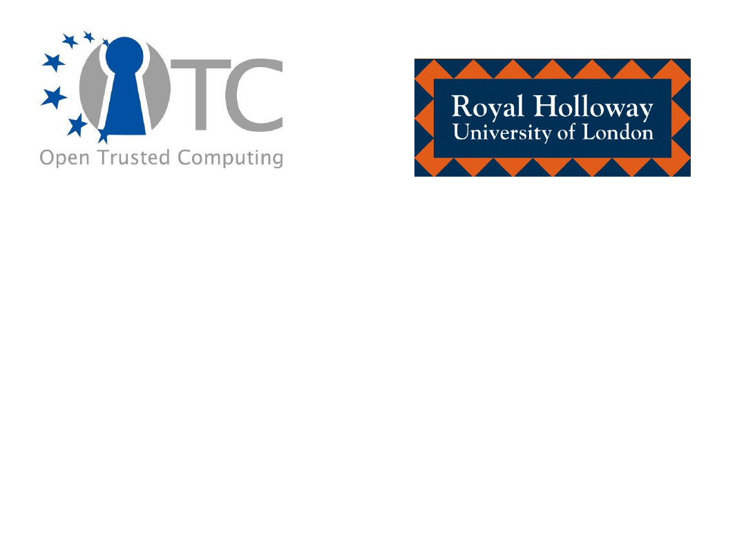
Trusted Computing Applications, part 1
(Operating Systems)
Stéphane Lo Presti
Royal Holloway, University of London
Stephane.Lo-Presti@rhul.ac.uk

www.opentc.net
2 April 2007
2
Introduction (1)
• Trusted Computing requires changes to the hardware
and the software, which for software means primarily
changes to the Operating System (OS).
• The OS is hardened by leveraging the underlying
Trusted Computing-aware elements. Further
modifications are necessary to build “Trusted OS”.
– One major change is to try to move away from monolithic
and heavy OSs to better designed and lighter
architectures.
– But you have to bring the “best of both worlds” to
security-aware companies and functionality-hungry
individuals.

www.opentc.net
2 April 2007
3
Introduction (2)
• We will cover the following systems:
– Microsoft NGSCB;
– Windows Vista;
– Unix and Linux;
• Open Trusted Computing;
• EMSCB;
– Apple Mac OS X.

www.opentc.net
2 April 2007
4
The TSS (TCG Software Stack) (1)
• The TCG designed the TPM with a small set of
functionalities so that it could be implemented as an
inexpensive component.
• In order to complement and extend the TPM
functionalities, the TCG specified a TCG Software Stack
(TSS) that is the (software) interface between
applications and the TPM (through the TPM driver).
• More about the TSS in the next lecture.
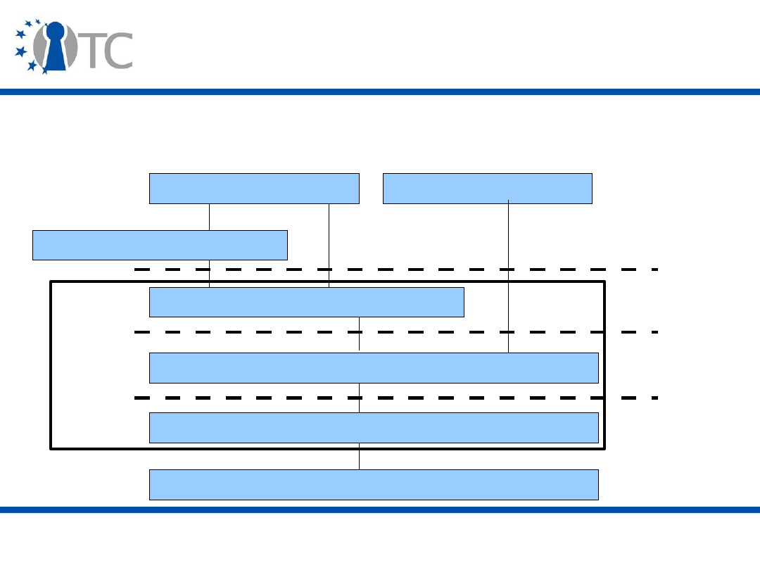
www.opentc.net
2 April 2007
5
The TSS (TCG Software Stack) (2)
• The TSS is composed of three layers, each one providing
a different set of functionalities:
TPM
TSS Device Driver Library (TDDL)
TSS Core Services (TCS)
TSS Service Provider (TSP)
Crypto Service Provider
Local Application
Remote Application
TSS
TSPI
TCSI
TDDLI

www.opentc.net
2 April 2007
6
Microsoft NGSCB
• The Microsoft initiative was originally introduced under
the name Palladium.
• In January 2003, the name Palladium was dropped,
officially because the name had already been
trademarked by another company.
• The work has continued under the name NGSCB, which
stands for Next Generation Secure Computing Base.
• NGSCB aims to provide robust access control to OSs and
applications so that they can protect themselves against
other software running on the platform.
• NGSCB is not incorporated in Windows Vista, but it
should be part of the future Windows Server codename
Longhorn.
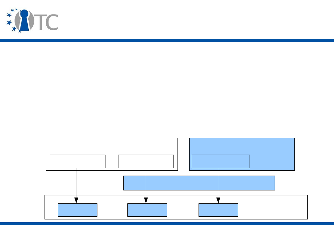
www.opentc.net
2 April 2007
7
NGSCB Architecture (1)
• NGSCB is built around:
– A Cryptographic chip called the Security Support Component
(SSC), or Security CoProcessor (SCP), i.e. a TPM v1.2;
– A lightweight isolation kernel (or Security Kernel);
– A mass market OS and untrusted applications (or left-hand
side);
– High assurance components (or right-hand side).
Device
Device
Device
Hardware
Isolation Kernel
Device Driver
Guest OS (mass market)
High Assurance Guest
Device Driver
Device Driver

www.opentc.net
2 April 2007
8
NGSCB Architecture (2)
• The Security CoProcessor (SCP) securely stores and
accesses cryptographic keys, and provides some
protected storage (registers).
• The isolation kernel isolates the various guests and
controls access to the devices.
• The mass market OS is a legacy system providing a
wide range of functionality to the user. It should run in
NGSCB almost unaffected from the point of view of
performance and functionalities.

www.opentc.net
2 April 2007
9
NGSCB Architecture (3)
• High assurance components are small components with
limited and well-defined functionality. The user can have
confidence that these components behave correctly.
– These components are, for example, used in critical
systems, e.g. critical infrastructure or military
environment.

www.opentc.net
2 April 2007
10
NGSCB Services (2)
• NGSCB provides the following services to its guests:
– Persistent protected storage
• Seal and unseal;
• Monotonic counter;
– Attestation
• Quote;
• PkSeal and PkUnseal: applications can remotely seal
information to a particular program on the remote platform.

www.opentc.net
2 April 2007
11
NGSCB Services (3)
• Sealed storage is designed to reveal no platform-
identifying information. At both hardware and software
layers, Seal adds randomness to each sealed data object
so that malicious software calling Seal repeatedly on the
same data is returned a different value each time.
• The user must specifically authorise software to perform
attestation. The High Assurance Guest can let users
restrict the parties with which attestation is used.

www.opentc.net
2 April 2007
12
NGSCB Services (4)
• Attestation mechanisms can provide cryptographic keys
to programs in order to use (slightly modified)
cryptographic protocols:
– Public key encryption using PkSeal(remote program
identity, machine key);
– Public key decryption using PkUnseal(program identity,
machine key);
– Signature using Quote.

www.opentc.net
2 April 2007
13
Modifications to the hardware (1)
• NGSCB runs on open hardware architectures, i.e. systems
allowing arbitrary peripherals to be connected.
• But the NGSCB features require some modifications to the
hardware platform.
– Input/Output (I/O) paths can be created so that information is
communicated only between the program and the user using
the device, ensuring the integrity and confidentiality of the
communication.
• Trusted path for Intel LT, and I/O control via the Virtual
Machine Control Block (VMCB) for AMD-V.
– The chipset must provide an access control to Direct Memory
Access (DMA) devices, so that the isolation layer can
arbitrate access to the devices between the guests.
• NoDMA table for Intel LT, and Device Exclusion Vector
(DEV) for AMD-V.
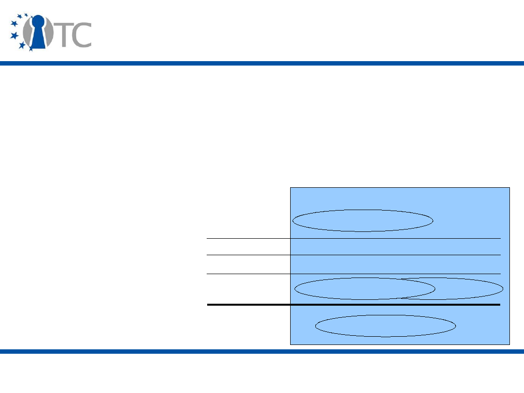
www.opentc.net
2 April 2007
14
Modifications to the hardware (2)
– The isolation kernel should be in control of the various
guests. But, as mass-market OSs are running in Ring 0
(currently the most privileged level of execution), the CPU
needs to provide a more privileged Ring (“-1”) to run the
isolation layer under unmodified OSs.
• Privileged ring 0 for Intel LT, and host mode for AMD-V.
Processor
Ring 3
Ring 2
Ring 1
Ring 0
Applications
Operating System
Operating System
Ring -1
Isolation Layer

www.opentc.net
2 April 2007
15
Modifications to the hardware (3)
• NGSCB relies on certain extensions of the hardware
platform to keep the isolation layer small in size.
– The isolation layer can display the output of the various
components without the need for a display driver. This is
implemented as a simple circuit combining the outputs of
the various guests and controlled by the isolation layer.
• Intel LT's Trusted Surface.
– High Assurance Guests can be started via a dynamic boot
that does not require the platform to be physically
rebooted. This is implemented as a new CPU instruction.
• GETSEC for Intel LT, and SKINIT for AMD-V.

www.opentc.net
2 April 2007
16
Authenticated boot
1. Set the core platform hardware into a well-defined state
(similar to reset);
2. Protect the program from Direct Memory Access (DMA)
devices;
3. Compute the program identity of the program by
hashing the contents of the memory region in which it
was previously laid out;
4. Record this program identity into a special, otherwise
unmodifiable, register of the Security CoProcessor (SCP);
5. Ensure that the program can initialise itself without
interruption;
6. Transfer control to the entry point of the program.

www.opentc.net
2 April 2007
17
Isolation Layer (1)
• The Isolation layer executes several OSs in parallel and
controls access to the platform resources.
• The isolation layer combines the properties of a Virtual
Machine Monitor (VMM) and an exo-kernel.
– VMM: few modifications to the guest OS;
– Exo-kernel: devices can be exported to guest OS.

www.opentc.net
2 April 2007
18
Isolation Layer (2)
• The problem of Direct Memory Access (DMA) devices
accessing all the physical memory is solved via a DMA
policy map controlled by the isolation kernel and
enforced by the hardware.
– Guest OSs can be authorised by the isolation layer to
manage Direct Memory Access (DMA) Devices.
• Memory is virtualised, and pages are organised
according to the Page Table Edit Control (PTEC)
algorithm.
– Any attempt by a guest to edit a page map traps to the
isolation kernel which consults its security policy to decide
whether or not the guest is allowed to modify the page.

www.opentc.net
2 April 2007
19
The Nexus (1)
• For the High Assurance Guest, Microsoft proposed a
secure kernel called the Nexus.
• The Nexus only has basic OS functions:
– Process and Thread Management;
– Memory Management;
– Input/Output (I/O) Management;
– Interrupt handling (Hardware abstraction).
• The Nexus provides sealing and attestation to
applications (called Nexus Computing Agents/NCA).

www.opentc.net
2 April 2007
20
The Nexus (2)
• But the Nexus is not a complete Operating System, as it
does not have:
– A File System;
– Networking;
– Kernel Mode (or Privileged) Device Drivers;
– Advanced Display features (e.g. Direct X);
– Scheduling.
• The Nexus has no pluggable components.
– All of the kernel is loaded at boot time and its hash value
is stored in a PCR.
• A Nexus Manager can be implemented in the mass-
market OS to communicate with the Nexus.

www.opentc.net
2 April 2007
21
The Nexus (3)
• System upgrades require that information is resealed to
the new version of the system. This can be done in
different ways:
– Provide the code identity of the new kernel and ask the old
system to reseal the secrets (or a root secret protecting
them) to the code identity provided;
– Embed public keys in the system code, such that a digest
of the new system can be signed with the key of the old
system and, after the signature has been verified, the
secrets are sealed to the new system.

www.opentc.net
2 April 2007
22
Windows Vista (1)
• Windows Vista does not incorporate NGSCB.
• Two (Enterprise and Ultimate) of the six Vista editions
can use a TPM (v1.2), if it is present on the platform and
if the user chooses to use it.
• The Trusted Computing features of Windows Vista are:
– Secure Startup, to ensure boot integrity;
– Full Disk Encryption (BitLocker).
www.opentc.net
2 April 2007
23
Windows Vista (2)
• Vista's use of Trusted Computing follows this model:
Kernel
space
OS Software Services
TPM
TPM v1.2 Device Driver
TPM Base Services (TBS)
Admin
Tools
Key
Storage
Provider
3
rd
Party
Applications
Secure
Start-up
User
space
TPM
Services
TSS
TCS
TDDL
CNG
API

www.opentc.net
2 April 2007
24
TPM Base Services (1)
• The primary goals of the TPM Base Services (TBS) are to:
– Provide efficient sharing of limited TPM resources;
– Provide appropriate management of TPM resources across
power states;
– Provide prioritised and synchronised access to TPM
resources between multiple instances of TCG Software
Stacks (TSSs);
– Prevent TSSs from accessing TPM commands that should
be restricted, either because of platform limitations or
administrative requirements.

www.opentc.net
2 April 2007
25
TPM Base Services (2)
• The TBS is only accessible to Administrator and
Services.
– Possible entities: TCG Core Services (TCS), Administrative
tools, Key Storage Provider (KSP).
• The TBS acts as a context manager:
– Each entity communicating with the TBS accesses it
through a context object (TBS_HCONTENT) that is
protected from other entities.
– The TPM commands are scheduled according to priorities
(4 possible levels), and the TBS efficiently manages the
TPM resources (keys, authorisation, transport session) by
“virtualising” them.
• Virtual object handles are seen by the entities, while actual
handles are stored in, moved from and deleted from the TPM.

www.opentc.net
2 April 2007
26
TPM Base Services (3)
– The TBS manages the moving of keys to and from the
TPM, by using the commands TPM_SaveContext and
TPM_LoadContext.
• It converts virtual addresses to physical ones;
• It passes handles and byte streams to the command caller.
• The TBS additionally provides exclusive transport
sessions.
– In addition to confidentiality, a session is terminated if any
other software (entity or TBS) accesses the TPM during the
chain of commands.
• The TBS can block TPM commands according to group,
local or default policies
– Rationale: privacy, incompatibility (v.1.1 Deprecated
commands, specific implementations).

www.opentc.net
2 April 2007
27
TPM Base Services (4)
• The TBS passes a physical presence command through
to the driver and checks for command format errors (not
cryptographic parameters).
• The TBS reacts to power management events so that
the TPM state is not lost (cancels long duration
commands) and pending TPM commands are saved.

www.opentc.net
2 April 2007
28
TPM Base Services and 3
rd
Party
Components (1)
• Three Microsoft applications and services that rely on
TPM Base Services are provided:
– Secure start-up
– TPM administrative tools
• Front-end to TPM administrative commands;
• Examples: curtail use of TPM commands that may reveal
private information about users or workstations; remote
administration of workstations;
– Key Storage Provider (KSP)
• Interface to key generation, encryption and signing;
• Keys are stored in user or application profiles.

www.opentc.net
2 April 2007
29
TPM Base Services and 3
rd
Party
Components (2)
• The "3rd-party Application" and TCG Software Stack
(TSS) are third-party components that rely on TPM Base
Services (TBS).
– Microsoft has no plans for a v1.2 compliant TSS;
– As the TBS corresponds to the TSS Device Driver Library
(TDDL) layer of the TCG Software Stack (TSS), TSS vendors
must modify their TCG Core Services (TCS) layers.

www.opentc.net
2 April 2007
30
Secure Startup (1)
• Secure Startup provides an authenticated boot by using
the CRTM, and the TPM measurement and storage
facilities.
• It covers all components from the platform firmware
(BIOS or Extensible Firmware Interface/EFI) to the OS
logon component.
– Secure Startup offers no protection after the logon.
• Secure Startup uses memory-mapped I/O to
communicate with the TPM.
– No TPM Device Driver during the boot sequence.
www.opentc.net
2 April 2007
31
Secure Startup (2)
• The detailed boot sequence is the following:
• If an Extensible Firmware Interface (EFI) firmware is
used instead of the BIOS, the BOOTMGR includes the
components MBR and IPL.
BIOS
Option ROMs
MBR
IPL
BOOTMGR
OS loader
1
2
3
4
5
6
Configuration
Data
Configuration
Data
Partition
Table
BIOS: Basic Input/Output System
MBR: Master Boot Record
IPL: Initial Program Loader
BOOTMGR: Boot Manager

www.opentc.net
2 April 2007
32
Secure Startup (3)
• Secure Startup proceeds as follows:
– PCR[0] to PCR[15] are reset.
– The CRTM measures the firmware (BIOS or Extensible
Firmware Interface/EFI) and its associated data (hardware
configuration), stores the measurements in PCR[0] and
PCR[1], and starts the firmware.
– The firmware measures the option ROMs and its
configuration data, and stores the measurements into
PCR[2] and PCR[3].
– Similarly, measurements of the Master Boot Record (MBR)
code portion and the partition table are stored respectively
into PCR[4] and PCR[5].

www.opentc.net
2 April 2007
33
Secure Startup (4)
– The Master Boot Record (MBR) then starts by determining
the active boot partition, loads the first sector of the boot
partition, measures the first 512 bytes of that sector
(Initial Program Loader/IPL) and stores the measurement
into PCR[8]. The boot sector loads and measures the
remaining boot code, and stores the measurement into
PCR[9].
– The boot code searches and loads the BOOTMGR boot
manager, measures it and stores the measurement into
PCR[10].
– Several auxiliary pieces of information can be measured
and their measurements stored into PCR[11], for example
the current boot status, some Operating System secrets
and the BitLocker encryption key.

www.opentc.net
2 April 2007
34
Secure Startup (5)
– BOOTMGR transfers control to the OS loader for the
specified partition. The OS loader ensures the integrity of
all Windows components before transferring control to the
operating system. The operating system then ensures the
integrity of system files (hibernation, swap, crash) and all
executables loaded up to, including, and after an
authenticated logon.
• In the case of an Extensible Firmware Interface (EFI)
firmware, the boot sequence is shorter.
– The measurements of the EFI BOOTMGR are stored in
PCR[4] and PCR[8] (PCR[9] and PCR[10] are not used).

www.opentc.net
2 April 2007
35
BitLocker Drive Encryption
• BitLocker Drive Encryption (BDE) provides full volume
encryption of the Windows volume, which helps protect
data on a lost or stolen machine against compromise.
• In order to provide a solution that is easy to deploy and
manage, a Trusted Platform Module (TPM) 1.2 chip is
used to store the keys that encrypt and decrypt the
Windows volume.
• More about BDE in the next lecture.

www.opentc.net
2 April 2007
36
Other services of Windows Vista
• Vista provides APIs to interact with:
– The TPM via the Win32_tpm class
• Methods: Enable, Disable, Clear, IsOwned,
IsPhysicalPresenceHardwareEnabled, AddBlockedCommand
– The TPM Base Services;
– Bitlocker via the Win32_EncryptableVolume class.
• The Windows Security Centre is the user interface to the
Trusted Computing features.
• The Network Access Protection system should support
Trusted Network Connect (TNC).

www.opentc.net
2 April 2007
37
Unix and Linux (1)
• TrustedBSD, SELinux, Trusted Solaris or Adamantix
(Trusted Debian) have no relationship with Trusted
Computing.
– They implement Mandatory Access Control (MAC).
– But all their security features can be reinforced by Trusted
Computing. For example, the Trusted Linux Client system
implements access control based on integrity properties:
• The Extended Verification Module (EVM) stores authenticated
file metadata (file hash, MAC labels, version number) in the
extended file attributes. The TPM is used to securely store the
kernel key and HMAC the file attributes. Files are verified
once at open/execute time, and the verification is cached.
• The Simple Linux Integrity Module (SLIM) classifies programs
as trusted or untrusted based on the verifications done by the
EVM, and then enforces the access policy.

www.opentc.net
2 April 2007
38
Unix and Linux (2)
• Linux distributions like Trusted Gentoo implement some
of the Trusted Computing technologies.
• GNU/Linux has a simple and complete support of
Trusted Computing via various independent projects:
– A TPM driver (libtpm) is available for all TPM chips and is
included by default in the Linux kernel since version 2.6.12
(June 2005);
– FreeBIOS and OpenBIOS implement the Core Root of Trust
for Measurement (CRTM);
– Lilo and tGrub boot loaders enable the measurement of
the post-boot components (OS, VMM);

www.opentc.net
2 April 2007
39
Unix and Linux (3)
– TrouSerS TCG Software Stack (TSS);
• TrouSerS includes a tpm-tools package that is used to create
AIKs, extract the EK certificate, take and clear TPM
ownership, bind and unbind data, seal and unseal data, read
and extend PCRs.
– TPM Manager is a GUI used to easily launch TPM and TSS
commands.
• A TPM emulator is also available for Linux, with most
TPM commands implemented and a TPM Device Driver
Library (TDDL) included. It is available at
http://tpm-emulator.berlios.de
.
• We will look at examples of Trusted Computing Linux
from two research projects:
– Open Trusted Computing (European);
– EMSCB (German).

www.opentc.net
2 April 2007
40
Open Trusted Computing (1)
• The Open Trusted Computing (OpenTC) project is a
European Consortium.
– It is made of 23 partners from both the industry (HP, IBM,
Infineon, AMD, SuSE) and academia (UK, IT, BE, DE, AT,
BG, HU, TR);
– It brings together:
• Theoretical and practical aspects of Trusted Computing;
• Virtualisation and Trusted Computing technologies;
• The Xen and L4 virtualisation technologies;
• Different platforms (PC, Server, Mobile).
– OpenTC is building an Open-Source Software (OSS)
environment (Novell SuSE).

www.opentc.net
2 April 2007
41
Open Trusted Computing (2)
• The project's objectives are:
– Open Specification, Implementation, and Validation;
– Explicit Policies Separated from Mechanisms;
– User-friendly;
– Multilateral Security and Privacy;
– Scalability.
• The long term goal is the creation of the foundations for
a Trusted OS running on virtualisation technologies.

www.opentc.net
2 April 2007
42
Open Trusted Computing (3)
• The project will prototype (Proof-of-Concept) several
applications, including:
– Trusted WYSIWYS (What You See Is What you Sign) for
digital signing and verification;
– A DRM solution for multimedia systems, based on the
MPEG-21 Rights Expression Language;
– A Trusted Computing-based Encrypted File Service;
– Multi-factor authentication to local and remote computers;
– A trusted OS layer for mobile technology.
• See next lecture for a demo of a simple Trusted Banking
scenario.
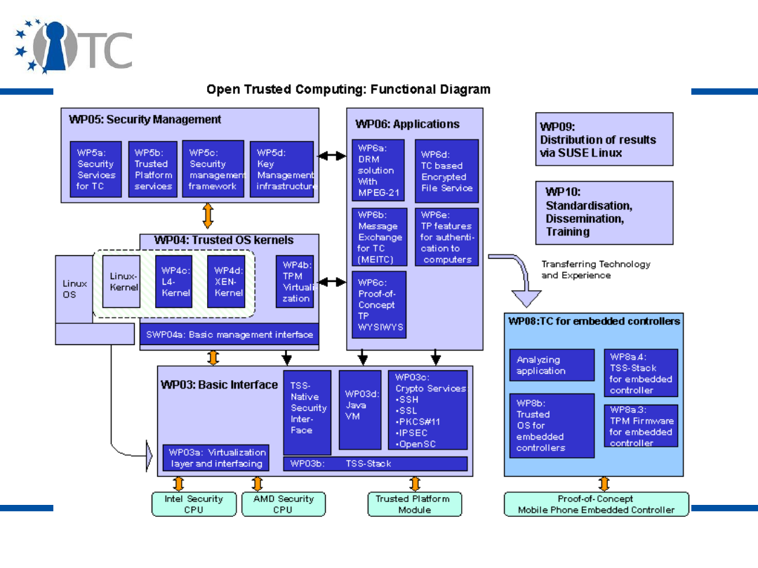
www.opentc.net
2 April 2007
43
Open Trusted Computing Structure (1)

www.opentc.net
2 April 2007
44
Open Trusted Computing Structure (2)
• At the lowest level, hardware Trusted Computing
mechanisms are leveraged for boot loaders, operating
systems and virtualisation layers via a basic driver and a
software stack.
• At the application level, the PKCS#11 interface will be
supported, SSL and SSH are being integrated with
Trusted Computing mechanisms, and isolation
mechanisms provided by the hardware platform (CPU,
Input/Output) will be interfaced with the operating
system layers.
• Trusted Computing mechanisms can be provided in an
OS-independent way through a common management
interface (Basic Management Interface/BMI), that can
also be used for remote management.

www.opentc.net
2 April 2007
45
Open Trusted Computing Structure (3)
• Methods and protocols for remote attestation of trusted
OS kernels, policy, configuration and network
management, as well as a key management
infrastructure (utility computing, GRID-like scenarios and
service hosting) are being developed.
• Verification of the trustworthiness of the system is also
investigated, looking for example at a Common Criteria
certification. Open methodologies, such as ISECOM’s
Open Source Security Testing Methodology (OSSTM), are
used to give guidance to designers, implementers, and
independent evaluators.
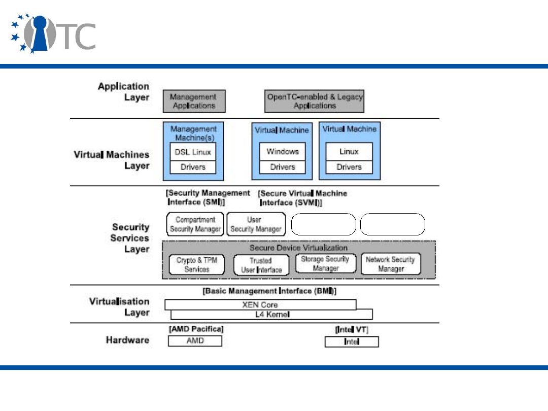
www.opentc.net
2 April 2007
46
Open Trusted Computing Architecture (1)
Integrity
Manager
Security Policy
Manager

www.opentc.net
2 April 2007
47
Open Trusted Computing Architecture (2)
• The layered architecture of the OpenTC system makes
use of the various security features available:
– At the hardware level, the OpenTC system leverages the
hardware extensions of the Intel LT and AMD-V platforms.
• Xen currently uses the AMD-V extensions to manage VMs.
– The virtualisation layer can run Xen or L4, with a Basic
Management Interface (BMI) to start, stop, suspend, and
resume hosted OS instances.
– The security services layer provide general security
services to the system.

www.opentc.net
2 April 2007
48
Security Services Layer (1)
• The
Secure Device Virtualisation
simplifies and manages
the secure virtualisation of:
– Cryptographic and TPM services;
– User Interface;
– Storage;
– Network.
• The
Compartment Security Manager
manages the life-
cycle and the security policies of each compartment.
This includes integrity constraints, permissions, and
global identifiers for each compartment. The
compartment security manager
can be used to prove
selected security properties to peers.

www.opentc.net
2 April 2007
49
Security Services Layer (2)
• The
User Security Manager
manages the users of the
system and enables authentication of individual users.
• The
Integrity Services Manager
maintains the integrity
of the system and is in charge of sealing, measurement
and attestation.
• The
Security Policy Manager
deals with the creation,
access and storage of policies for the various system
components (VM, virtual device, security service).

www.opentc.net
2 April 2007
50
EMSCB (1)
• EMSCB is a German project involving Infineon, SAP,
Blaupunkt, Sirrix, Universities of Bochum and Dresden.
• It is based on the PERSEUS Security Framework and the
L4 microkernel.
– PERSEUS: a simple and modular security kernel;
– L4: a family of microkernels (minimal OS executing
services as user applications) defined by the L4 API.
• The main objective of the EMSCB project is the
realisation of a minimal and therefore manageable,
stable and evaluable security kernel for conventional
hardware platforms.
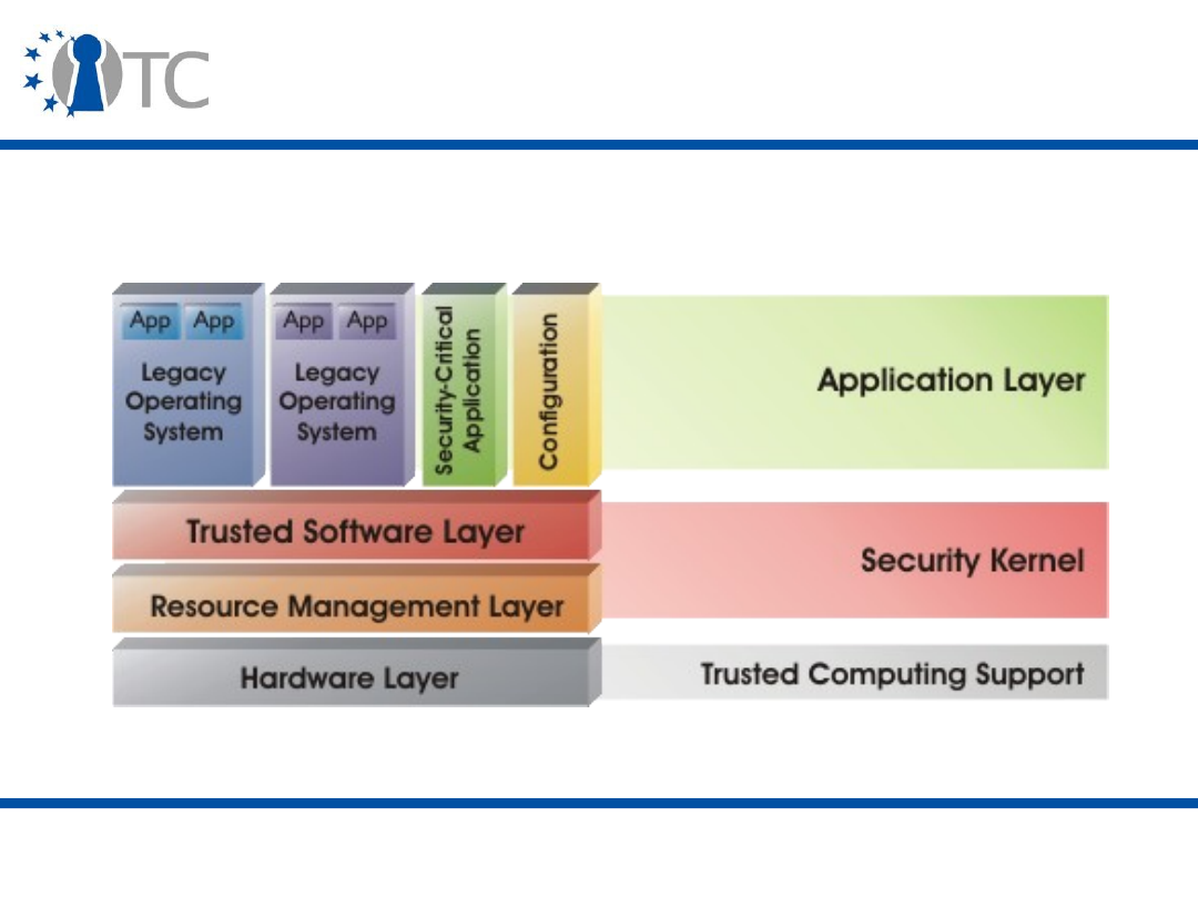
www.opentc.net
2 April 2007
51
EMSCB (2)
• The architecture of the EMSCB system is the following:

www.opentc.net
2 April 2007
52
EMSCB (3)
• The
Resource Management
layer provides an abstract
interface of the underlying hardware resources such as
interrupts, memory and hardware devices. It shares
these resources and enforces access control.
• The
Trusted Software
layers extends the interfaces of
the underlying services with security properties and
ensures isolation of the applications executed on top of
this layer. Security services include secure user
interface (trusted GUI, trusted path) and secure booting.
• At the
Application
layer, security-critical and non-critical
applications run in parallel. A legacy OS is used to
provide end-users with a common user interface and a
backward-compatible application binary interface (ABI).
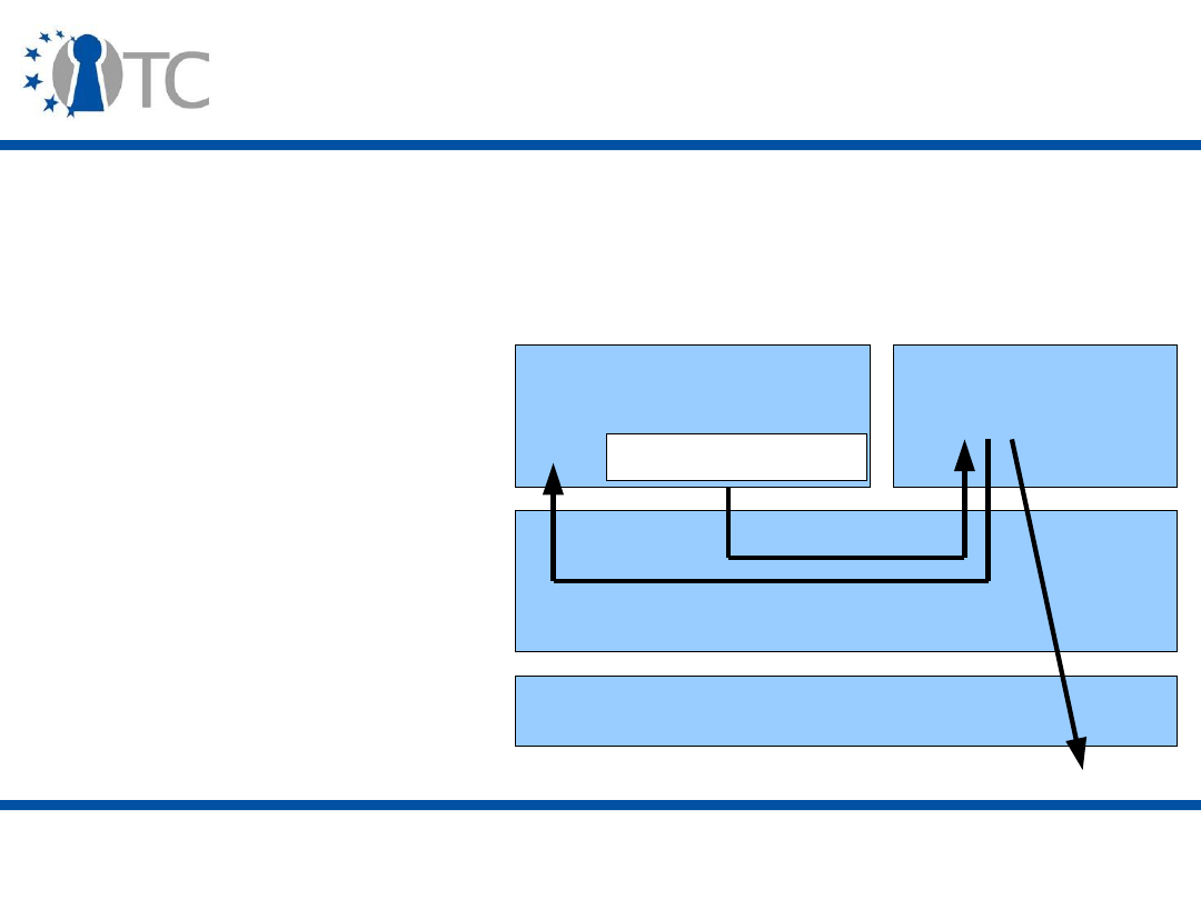
www.opentc.net
2 April 2007
53
EMSCB (4)
• The system implemented by the EMSCB project is called
Turaya and is freely available (binary and code).
• Two prototype applications have been implemented:
– Disk encryption
(Turaya.Crypt)
– VPN communication
(Turaya.VPN)
HW
Communication Stub
Linux
Trusted
Application
Security kernel
Encryption
Network
Communication

www.opentc.net
2 April 2007
54
EMSCB (5)
• Turaya.VPN implements an IPSec-based VPN client that
encrypts communication using a key only accessible if
the security kernel and the VPN application have not
been tampered with. The client runs isolated from the
calling application and access to the network is
controlled by the security kernel.
– The integrity of the security kernel is checked at boot time
using the TPM, while the integrity of the VPN application is
checked by the security kernel.
• Turaya.Crypt implements a device encryption module
that runs independently from the legacy OS. The user
provides the encryption password either at boot time, or
at run time via a Trusted GUI (for a removable media,
e.g. USB, CD, Smartcard).

www.opentc.net
2 April 2007
55
Apple
• Apple does not appear to have plans to use Trusted
Computing.
• It has been suggested that Mac OS X uses the TPM when
available (on the Intel Mac platform) to protect the OS
from piracy, but this is wrong.
• Software support is available via Open-Source Software
(OSS), based on the FreeBSD Unix system, but it is not
distributed by Apple.

www.opentc.net
2 April 2007
56
Conclusion
• Operating systems are already changed by Trusted
Computing:
– Better security provided by the trusted platform and the
TPM;
– Virtualisation protecting them and limiting the effect of
their actions.
• They are in turn changing the software landscape:
– Transparently protecting software;
– Providing security at all levels.
• But there is still a long way to go before they fully
exploit Trusted Computing's potential.
• Next: Trusted Computing Applications, part 2,
Applications

www.opentc.net
2 April 2007
57
References (1)
• NGSCB
– Paul England et al. A Trusted Open Platform. IEEE
Computer, vol. 36, no. 7, pp. 55-62, July 2003.
– Marcus Peinado, Paul England and Yuqun Chen. An
Overview of NGSCB. In Chris Mitchell ed., Trusted
Computing, 2005, IEE Press, pp. 115-141.

www.opentc.net
2 April 2007
58
References (2)
• Windows Vista
– Trusted Platform Module Services in Windows Vista.
http://www.microsoft.com/whdc/system/platform/pcdesign/
TPM_secure.mspx
– TPM Base Services. http://msdn2.microsoft.com/en-
us/library/aa446796.aspx
– Secure Startup - Full Volume Encryption: Technical
Overview.
http://www.microsoft.com/whdc/system/platform/pcdesign/
secure-start_tech.mspx
• Linux:
– TrouSerS:
http://trousers.sourceforge.net/
– Linux and trusted computing.
http://lwn.net/Articles/144681/

www.opentc.net
2 April 2007
59
References (3)
• Open Trusted Computing:
–
http://www.opentc.net
– Dirk Kuhlmann et al. An Open Trusted Computing
Architecture — Secure virtual machines enabling user-
defined policy enforcement.
http://www.opentc.net/otc_HighLevelOverview/OTC_Archit
ecture_High_level_overview.pdf
• EMSCB:
http://www.emscb.de
• Apple: Amit Singh. Trusted Computing for Mac OS X.
http://www.osxbook.com/book/bonus/chapter10/tpm/

www.opentc.net
2 April 2007
60
The information in this document is provided “as is”, and no guarantee or
warranty is given that the information is fit for any particular purpose.
The user thereof uses the information at its sole risk and liability.
The Open-TC project is co-financed by the EC.
If you need further information, please visit our website
www.opentc.net or contact the coordinator:
Technikon Forschungs- und Planungsgesellschaft mbH
Richard-Wagner-Strasse 7, 9500 Villach, AUSTRIA
Tel.
+
43 4242 23355 – 0
Fax.
+
43 4242 23355 – 77
Email coordination@opentc.net
Open_TC EC Contract No: IST-027635

Trusted Computing Applications, part 2
(Applications)
Stéphane Lo Presti
Royal Holloway, University of London
Stephane.Lo-Presti@rhul.ac.uk

www.opentc.net
3 April 2007
2
Introduction (1)
• After hardware platforms and operating systems, we
now look at the next link in the “chain of trust”:
applications.
• Applications have different and more varied
requirements than hardware and Operating Systems
(OSs).
– They interact with the user.
– Functionality is essential and not all functionalities are
related to security.
• The TCG proposed the TCG Software Stack (TSS) to
cover application needs.

www.opentc.net
3 April 2007
3
Introduction (2)
• The foreseen Trusted Computing applications include:
– Secure VPNs and Peer-to-Peer systems;
– Strong authentication;
– Data protection;
– Privacy and Identity protection;
– E-Commerce.

www.opentc.net
3 April 2007
4
Introduction (3)
• We will examine:
– The TCG Software Stack (TSS);
– Windows Vista BitLocker;
– Secure banking;
– Digital Rights Management (DRM);
– Grid computing;
– Peer-to-Peer computing;
– Trusted Computing-specific applications and middleware.

www.opentc.net
3 April 2007
5
The TSS (TCG Software Stack) (1)
• The TCG designed the TPM with a small set of
functionalities so that it could be implemented as an
inexpensive component.
• In order to complement and extend the TPM
functionalities, the TCG specified a TCG Software Stack
(TSS) that is the (software) interface between
applications and the TPM (through the TPM driver).
– Functionalities such as auditing, transport sessions, non-
volatile monotonic counters and storage use the platform’s
main processor and memory space rather than the limited
TPM resources;
– Added functionalities include delegation and secure
timing.

www.opentc.net
3 April 2007
6
The TSS (TCG Software Stack) (2)
• The TSS is the (software) interface between applications
and the TPM (through the TPM driver).
– It can also be used by a system without a TPM to
communicate with other, possibly remote, TSSs.
• Some elements of the TSS are defined by the TCG
specification, others are left to be specified by the TSS
vendor. Certain elements of the specification are
optional.
• The TSS is not trusted, as it comprises code that can be
large and complex, and it can break some of the TPM
properties (i.e. privacy).
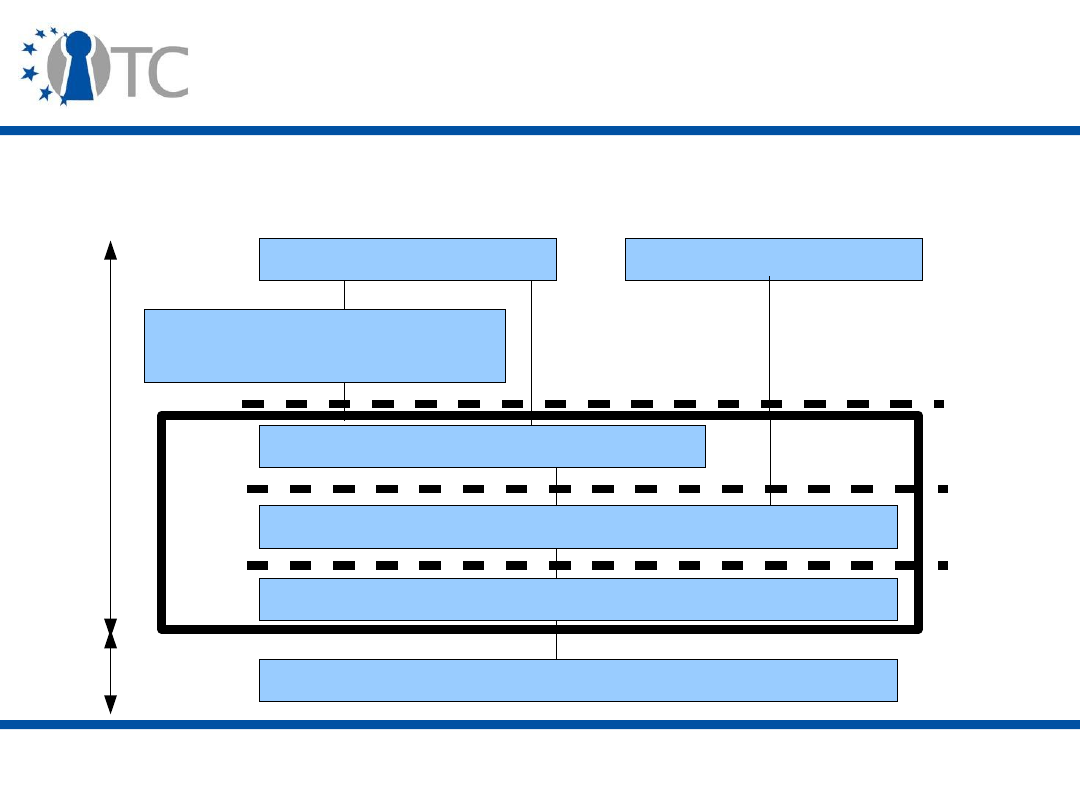
www.opentc.net
3 April 2007
7
The TSS (TCG Software Stack) (3)
• The structure of the TCG Software Stack (TSS) is the
following:
TPM
TSS Device Driver Library (TDDL)
TSS Core Services (TCS)
TSS Service Provider (TSP)
Cryptographic Service
Provider (CSP)
Local Application
Remote Application
TSS
TSPI
TCSI
TDDLI
Kernel
mode
User
mode
Remote Procedure
Call

www.opentc.net
3 April 2007
8
The TSS (TCG Software Stack) (5)
• The TSS Device Driver Library (TDDL) provides two
functions:
– A standard interface for the TPM so that all TPMs look and
behave the same at this interface (Tddli), abstracting the
TPM Device Driver and making the TSS OS-independent;
– Transition between the User and Kernel Mode (TPM Device
Driver).
• TDDL commands are sent at a byte level as a stream to
the TPM Device Driver.
• There is typically one TDDL per TPM and it is provided
by the TPM manufacturer. Access to the TPM is exclusive
and synchronised via the TDDL. The TCS is the typical
application interfacing with the TDDL.

www.opentc.net
3 April 2007
9
The TSS (TCG Software Stack) (6)
• The TSS Core Services (TCS) layer provides:
– All the TPM primitives and more sophisticated functions
such as key management;
– The Tcsi interface, designed to provide a straightforward,
simple method for controlling and requesting atomic
services from the TPM.
• There is typically one image of the TCS per platform,
executing as a system service in User Mode.

www.opentc.net
3 April 2007
10
The TSS (TCG Software Stack) (7)
• Example of TCS services:
– Serialising commands to the TPM from multiple processes
and threads;
– Coordinating the secure management of limited TPM
resources, e.g. Key Cache;
– Maintaining logs of all operations the platform owner has
chosen to audit;
– Managing TSS_PCR_EVENT structures, which provide
information about PCR extend events;
– Managing the platform credentials, so that software can
prove to remote platforms that it is working with a valid
TPM.

www.opentc.net
3 April 2007
11
The TSS (TCG Software Stack) (8)
• The TCS commands are very similar to the ones sent
directly to the TPM (e.g. TPM_Seal, etc.) and the TCS is
usually provided as an OS component. A TCS policy can
indicate which commands are authorised or not.
– The policy mechanism is left unspecified.
• TCS Contexts are used to create and manipulate TPM or
TCS Resources (e.g. keys, credentials).

www.opentc.net
3 April 2007
12
The TSS (TCG Software Stack) (9)
• Remote TSPs can access the TCS via a specific Remote
Procedure Call (RPC) mechanism.
– Specified as Web Services over SOAP (Simple Object Access
Protocol), but TSS vendors can also provide a proprietary
communication mechanism;
– The TCS policy indicates which connections are allowed or
disallowed.
• The TCS is used by low-level software that implements
specific services, e.g. middleware or OS components, and
the TSP and RPC servers.

www.opentc.net
3 April 2007
13
The TSS (TCG Software Stack) (10)
• The TSS Service Provider (TSP) layer contains the top-
most modules and providea a rich, object-oriented
interface (Tspi) to applications. While not an
architectural requirement, it is intended that the TSP
obtains many TCG services, such as TPM byte stream
generation, key management, etc., from the TCS.
– The TSP can implement application-defined policies;
– It also marshals data for TCS.

www.opentc.net
3 April 2007
14
The TSS (TCG Software Stack) (11)
• The TSP provides:
– Contexts that are used by applications to manage TPM
objects (e.g. policy, key, PCR); these contexts can be used
to connect threads in an application and, possibly remote,
TSSs;
– Cryptographic functions (e.g. Direct Anonymous
Attestation/DAA, Signature verification).
• The TSP is usually provided as a library and used by all
high-level applications (e.g. Cryptographic Service
Provider/CSP, user application).

www.opentc.net
3 April 2007
15
Direct Anonymous Attestation (DAA) (1)
• Direct Anonymous Attestation (DAA) was added in the
TPM/TSS specification version 1.2 following concerns
over Privacy-CAs (tracking, privacy).
• DAA provides anonymous (and pseudonymous) proof
that a key came from a genuine TPM without requiring a
third party anonymiser (zero-knowledge proof). DAA
uses a group signature scheme and ensures that the
issuer is not able to identify the signer of a DAA
signature.
• DAA involves heavy (and complex) computations and
not all TPMs implement it, but it can be outsourced to
the TSS.

www.opentc.net
3 April 2007
16
Direct Anonymous Attestation (DAA) (2)
• The DAA scheme is composed of:
– Actors: the platform, DAA Issuer, DAA Verifier (challenger);
– Protocols: DAA-Join, DAA-Sign.
• DAA-Join: the platform proves to the DAA Issuer that it
has a TPM-controlled, non-migratable secret
f
(generated from a seed and DAA Issuer information) by
providing a pseudonym of the form
N
1
f
(
N
1
is derived
from the DAA Issuer's name and is an element of a
suitable group). The DAA Issuer then provides to the
platform a credential in the form of a Camenish-
Lysyanskaya signature on
f
.

www.opentc.net
3 April 2007
17
Direct Anonymous Attestation (DAA) (3)
• DAA-Sign: the platform can sign a message using the
DAA credential and a pseudonym
N
2
f
chosen by the DAA
Verifier. The choice of this pseudonym determines the
anonymity properties of the attestation process.

www.opentc.net
3 April 2007
18
Windows Vista BitLocker (1)
• BitLocker Drive Encryption (BDE) is a Windows Vista
application that aims at protecting data from offline
viewing using a TPM v1.2.
– In an offline attack, an attacker boots an alternative
operating system.
– Offline attacks are a huge threat, because stored data can
have much more value than the computer itself.
– Bonus: secure decommissioning by deleting the keys.
• The solution involves two elements:
– Booting OS integrity check;
– System volume encryption with key sealed to the booted
OS.

www.opentc.net
3 April 2007
19
Windows Vista BitLocker (2)
• There are two volume categories:
– System volume (unencrypted)
• Master Boot Record (MBR), Boot manager and utilities;
– OS volume (encrypted)
• OS kernel, page/temp/hibernation file, data.
• BitLocker uses two keys:
– The Volume Master Key (VMK) that is protected by one of
five possible options (TPM, TPM+PIN, TPM+USB, USB,
Recovery password); if the TPM is used, the VMK is sealed
to the platform state (see Secure Startup, last lecture);
– The FVEK (Full Volume Encryption Key) that is encrypted
with the VMK and is used to encrypt the OS Volume.
• SRK authorisation value must be set to 20 zeros, so that
the user is not asked for several passwords.
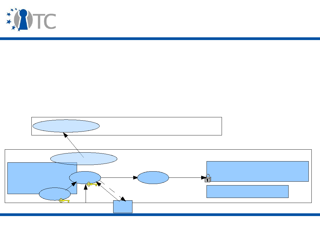
www.opentc.net
3 April 2007
20
Windows Vista BitLocker (3)
TPM
VMK
SRK
PIN
USB
Windows OS Volume
Recovery key
backup
decrypt
Network or WWW Server
System Volume
• After the user (or administrator) activates BDE in
Windows Vista:
– BDE verifies the partition layout and that the TPM is
activated;
– The user selects his desired recovery backup method;
– BDE encrypts the OS volume.
VMK: Volume Master
Key
FVEK: Full Volume
Encryption Key
FVEK
decrypt
Recovery key

www.opentc.net
3 April 2007
21
Windows Vista BitLocker (4)
• If the boot components or the system volume have been
modified, Windows Vista alerts the user and refuses to
release the VMK required to access protected volumes.
• The system then goes into a recovery mode, prompting
the user to provide a recovery key to allow access to the
System volume, or the key is accessed from the
enterprise backup server.

www.opentc.net
3 April 2007
22
Secure Banking (1)
• Online banking is becoming widespread.
– Banks need very high assurance to propose more services.
– Users must have few problems.
• The main aims of a secure banking application are:
– Protection of the user's credentials;
– The server needs to be assured that the service can only
be accessed by a trusted application;
– The service can neither be subverted nor changed by the
user, who keeps control of the service progression;
– Other system functionalities are unaffected by the service.

www.opentc.net
3 April 2007
23
Secure Banking (2)
• Typical security threats include:
– Phishing
• Attack where the attacker tricks the user into revealing some
of his personal information by making him think that he is a
valid entity or component;
• The typical sequence of actions is: access to a fake web
server (e.g. link in a spam email); get the user's credentials
from the browser when connecting; use the user's
credentials.
– Software vulnerabilities
• Trojans, Malware.

www.opentc.net
3 April 2007
24
Secure Banking (3)
• Countermeasures necessitate setting up a trusted path
from the user to the bank server, through the banking
application.
• Mechanisms that can be used to prevent these threats
include:
– Trusted virtual compartment with a different visual
appearance and a firewall;
– TLS server authentication with measured part of trusted
compartment in a server certificate;
– Mutual remote attestation through proxies;
– Multi factor authentication;
– Trusted I/O path (trusted GUI and keyboard).

www.opentc.net
3 April 2007
25
Secure Banking (4)
• We demonstrate a simple Secure Banking application
using the Open Trusted Computing system based on two
independent protection mechanisms:
– Client-side only (sealed protected storage);
– Client-server (remote attestation).
• On the client side, three compartments (Xen domains)
are executed:
–
dom0
: trusted service domain
• runs drivers, management and security services, proxy;
–
domT
: trusted domain (trusted browser);
–
domU
: vanilla domain (day-to-day operations).
• On the server side, policy is enforced via a proxy acting
as front-end to the web server.

www.opentc.net
3 April 2007
26
Secure Banking Demonstration (1)
• Step 0: Authenticated boot process, with measurements
by the CRTM (Trusted Computing-aware BIOS) of:
– Boot loader (tGrub modules e.g. OSLO for the Dynamic
Root of Trust for Measurement/DRTM);
– Virtualisation layer (Xen).
• Xen is started using AMD-V.
• The Trusted Service domain (dom0) is then measured
and started.
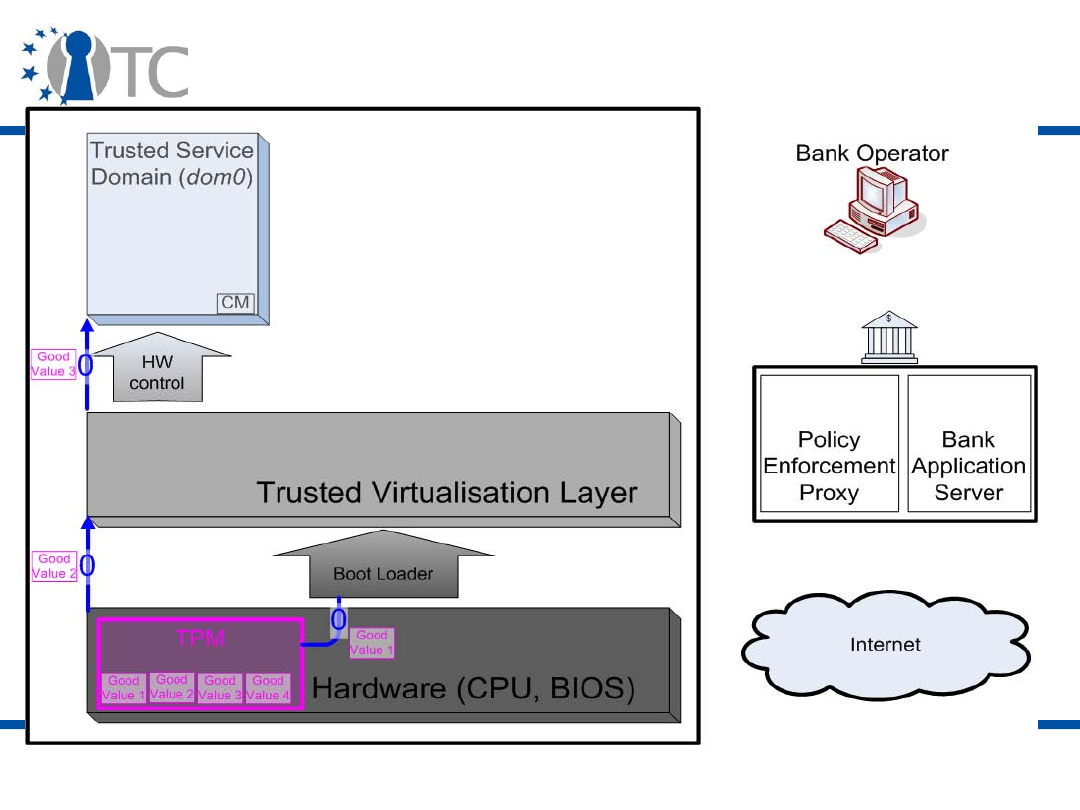
www.opentc.net
3 April 2007
27
Secure Banking Demonstration (2)

www.opentc.net
3 April 2007
28
Secure Banking Demonstration (3)
• Step 1: An untrusted domain (domU) is started from the
Compartment Manager (CM).
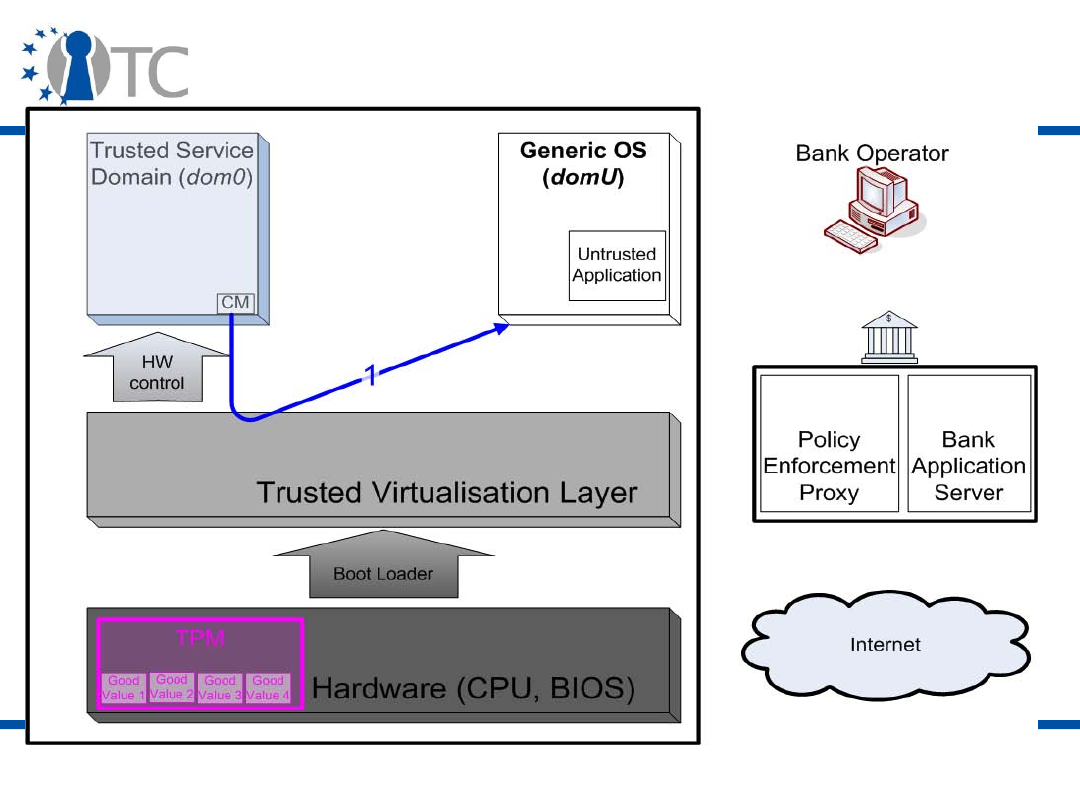
www.opentc.net
3 April 2007
29
Secure Banking Demonstration (4)

www.opentc.net
3 April 2007
30
Secure Banking Demonstration (5)
• Step 2: A trusted domain (domT) is started, which is
measured and the measurement stored in PCR[11].
– A different background picture is used to remind the
user of the trusted status of this domain.
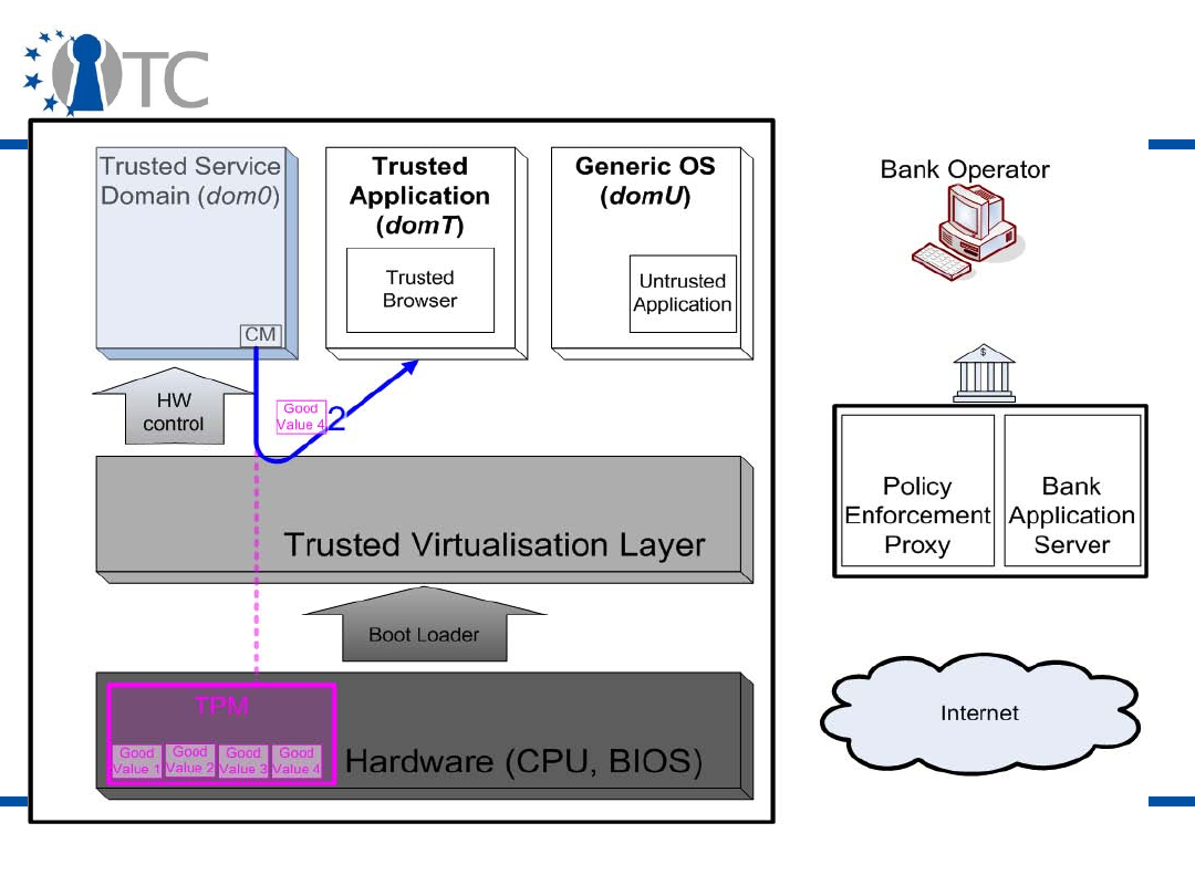
www.opentc.net
3 April 2007
31
Secure Banking Demonstration (6)

www.opentc.net
3 April 2007
32
Secure Banking Demonstration (7)
• Step 3: Take ownership of the TPM.
– The TPM has already been enabled via the Trusted
Computing-aware BIOS.
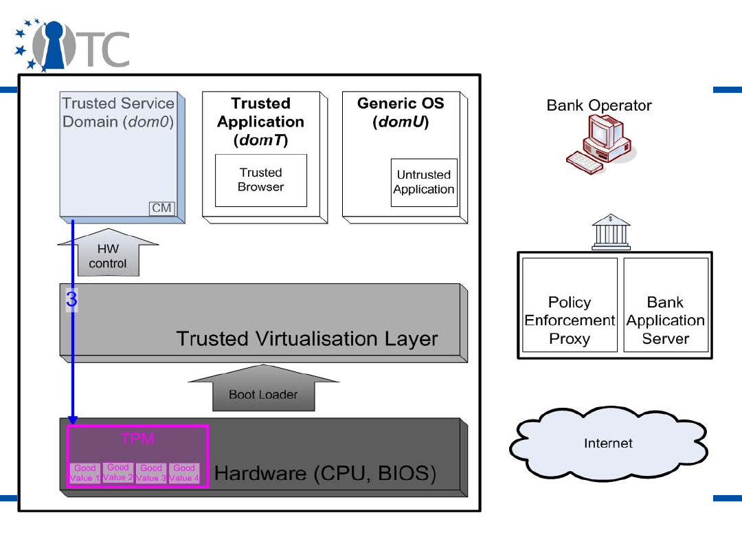
www.opentc.net
3 April 2007
33
Secure Banking Demonstration (8)

www.opentc.net
3 April 2007
34
Secure Banking Demonstration (9)
• Step 4: Create an identity key (AIK) and activate the
identity.
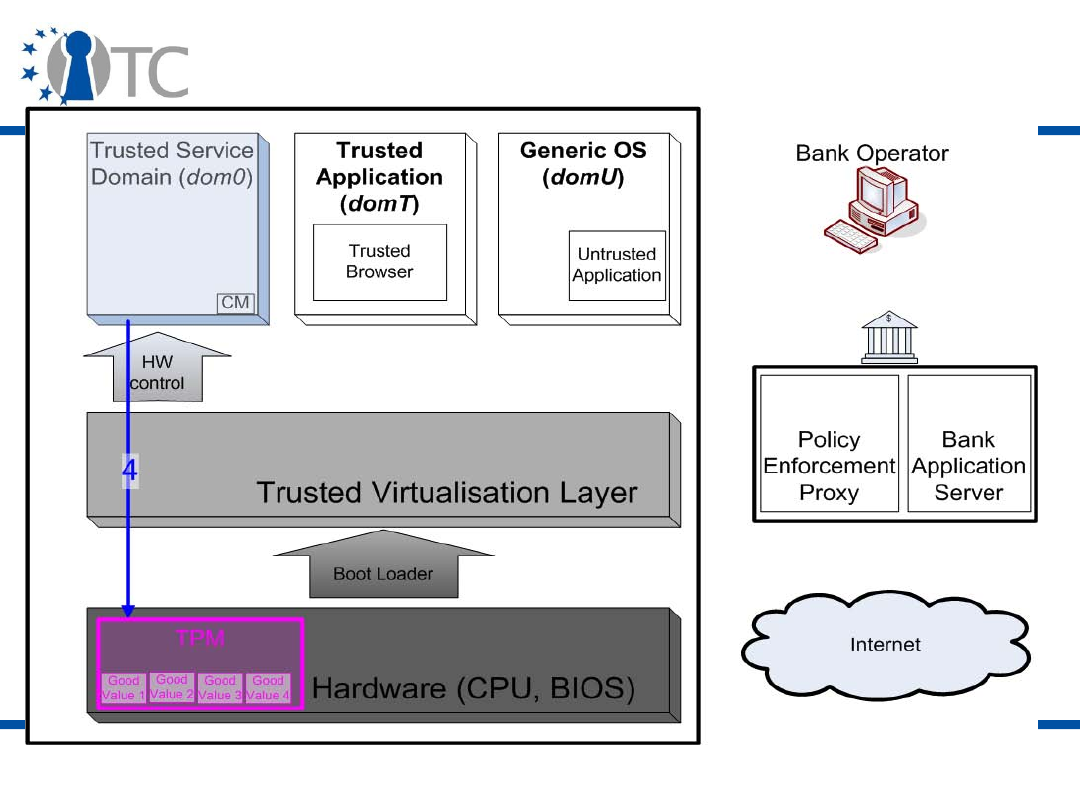
www.opentc.net
3 April 2007
35
Secure Banking Demonstration (10)

www.opentc.net
3 April 2007
36
Secure Banking Demonstration (11)
• Step 5: Register the platform and upload the platform
state to the Bank server.
– The platform state is stored in a file;
– A “bank operator” manually uploads the file to the
bank server.
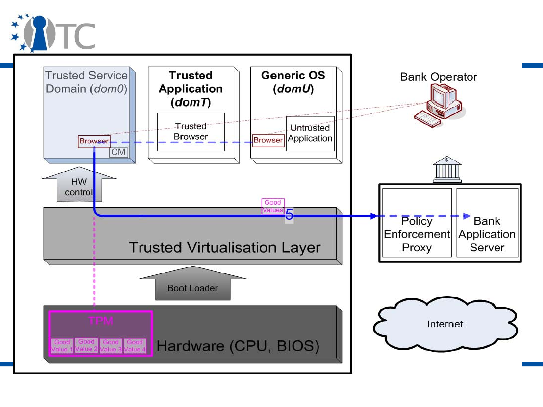
www.opentc.net
3 April 2007
37
Secure Banking Demonstration (12)

www.opentc.net
3 April 2007
38
Secure Banking Demonstration (13)
• Step 6: Enable the client platform state on the bank
server.
– The “bank operator” authorises access for the
platform state provided (done by default).
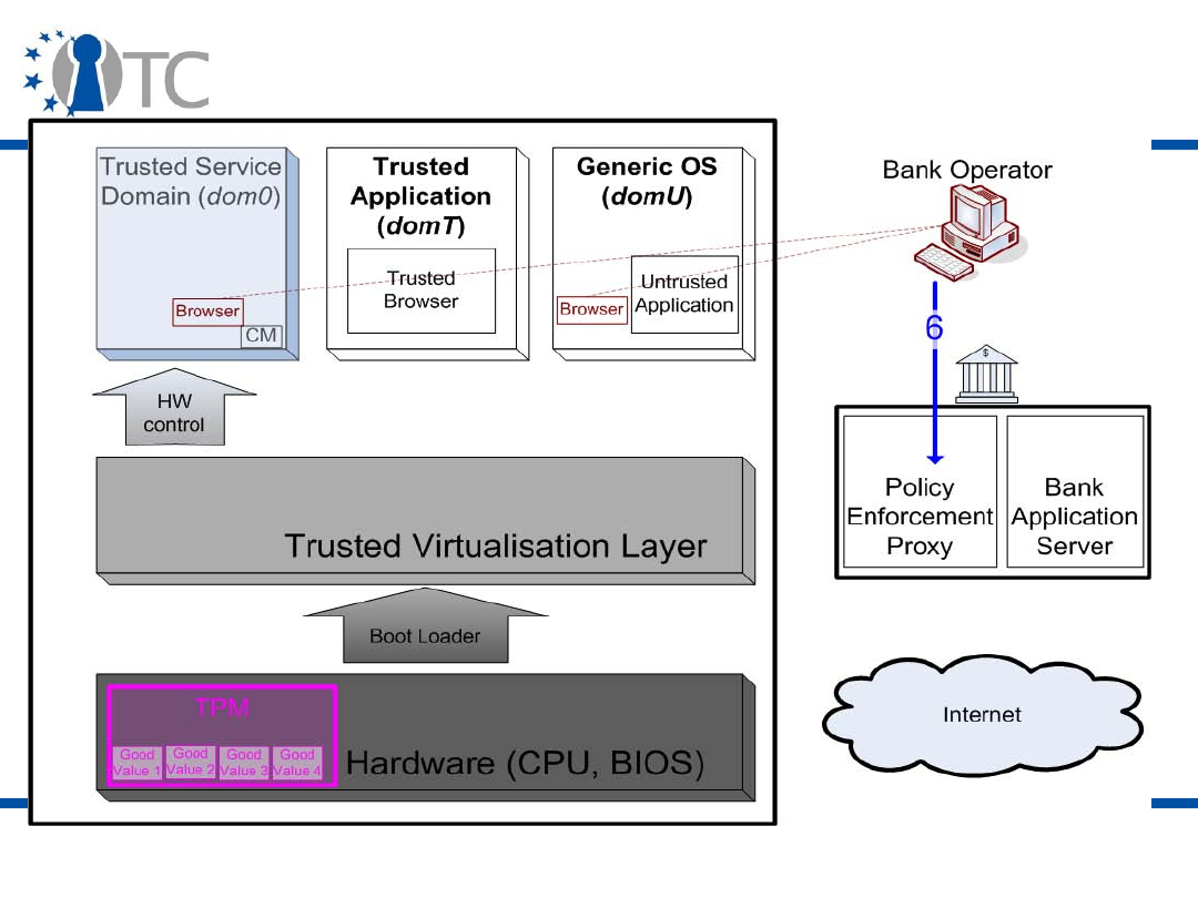
www.opentc.net
3 April 2007
39
Secure Banking Demonstration (14)

www.opentc.net
3 April 2007
40
Secure Banking Demonstration (15)
• Step 7: Start the client proxy.
– The client proxy is used to route accesses from the
trusted domain (domT) to the bank server;
– It creates two SSL tunnels using keys protected by
the TPM.
• One tunnel redirects to a real bank website via a
proxy on the bank server;
• The other tunnel connects to a web site on the
bank server.
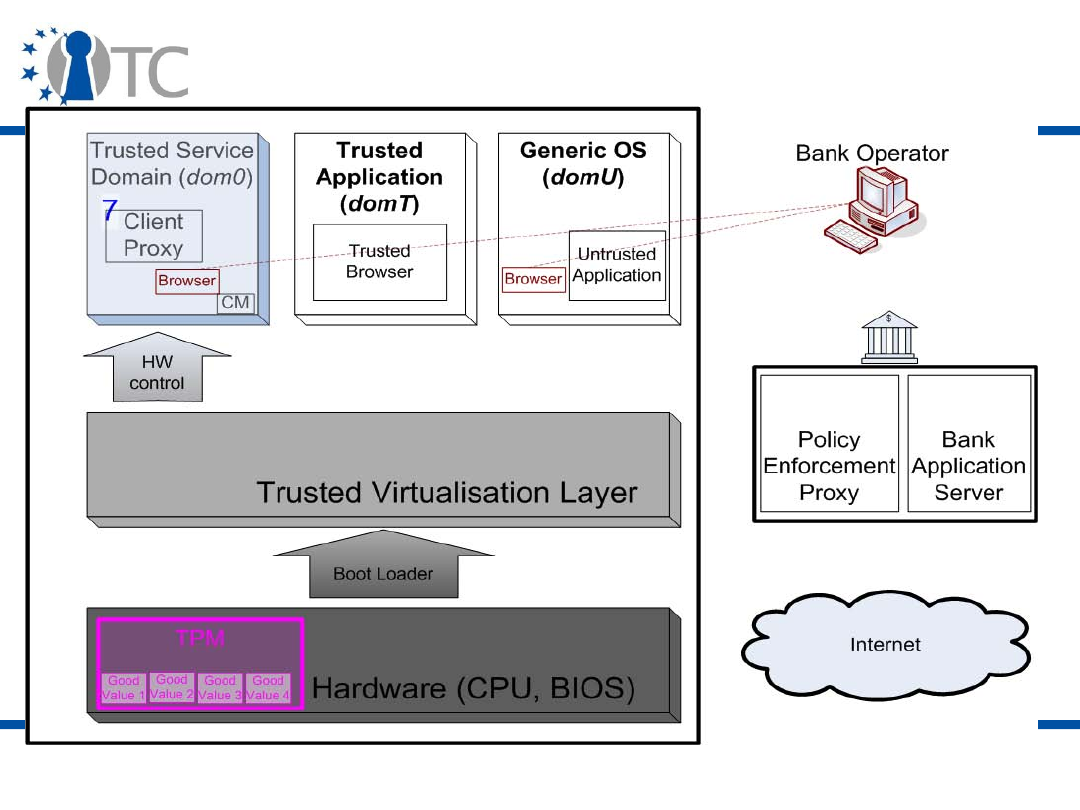
www.opentc.net
3 April 2007
41
Secure Banking Demonstration (16)

www.opentc.net
3 April 2007
42
Secure Banking Demonstration (17)
• Step 8: Communication with the Bank server.
– The user clicks on the weblinks (SSL tunnel 1 or 2) in
the trusted browser (domT).
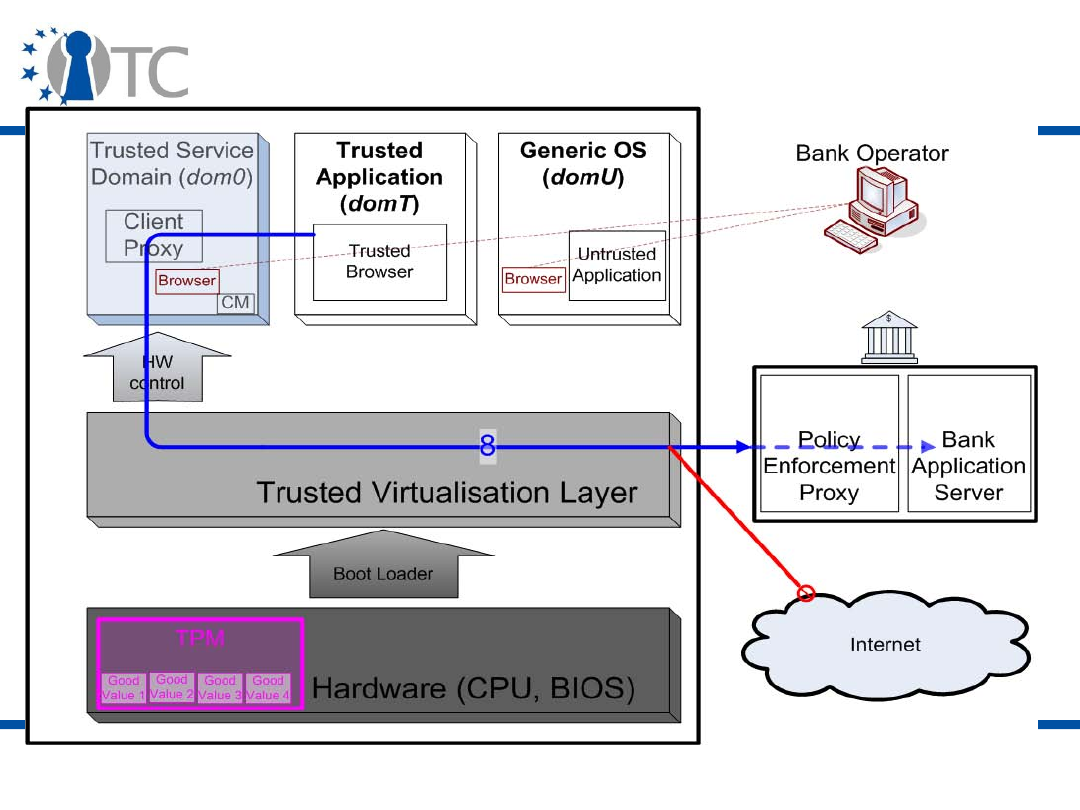
www.opentc.net
3 April 2007
43
Secure Banking Demonstration (18)

www.opentc.net
3 April 2007
44
Secure Banking Demonstration (19)
• Step 9: Untrusted communication.
– The user tries to access the bank proxy server from
the untrusted domain (domU).
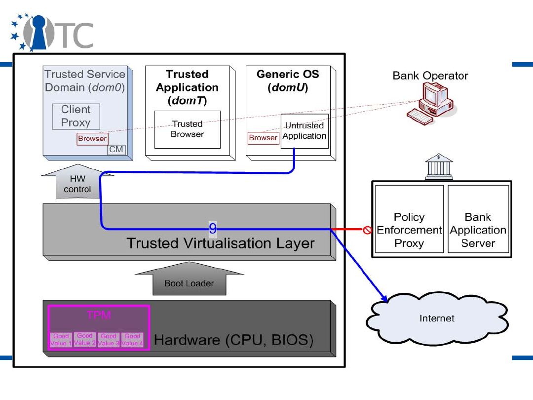
www.opentc.net
3 April 2007
45
Secure Banking Demonstration (20)

www.opentc.net
3 April 2007
46
DRM (1)
• Digital Rights Management (DRM) systems implement
access and usage rights in order to satisfy DRM
stakeholder's policies.
– They are complementary to content protection.
• DRM systems are traditionally used by publishers or
copyright owners to protect their digital data or
hardware against unrestricted access and usage.
• Companies use it to protect their assets.
– For example, hospitals protect patient records.
• Note that Trusted Computing is NOT targeted at DRM
systems but can greatly help their implementation.
– More on this in the last lecture.

www.opentc.net
3 April 2007
47
DRM (2)
• DRM applications are important applications on the
mobile platform (ringtones, games, music, video, etc.)
where it is harder to implement than on the PC platform.
• Policies are sometimes separated from the content they
are related to.
• There are two main threat categories:
– Bypassing the DRM agent; because of the possibility of
reverse engineering DRM solutions, such as media player
modifications and proprietary codecs, DRM has to be
implemented at a lower level (OS, hardware);
– Accessing the content while it is no longer protected
(memory, I/O).

www.opentc.net
3 April 2007
48
DRM (3)
• Possible uses of Trusted Computing for DRM include:
– Protecting the DRM agent's integrity;
– Monotonic counters and trusted timestamps for enforcing
usage rules;
– DRM content bound to a specific TPM or platform
configuration;
– Trusted I/O channels;
– Client platform attesting to the Content Provider;
– Secure migration of DRM content;

www.opentc.net
3 April 2007
49
DRM (4)
– Protected boundary around a legacy OS (or the
components related to the DRM agent, e.g. Java Virtual
Machine);
– Trusted virtualisation to support trusted DRM agent
running in a protected compartment;
– Specific protocols and data integrity mechanisms
supported by keys protected by the TPM.

www.opentc.net
3 April 2007
50
Grid Computing (1)
• Grid Computing is a form of computing where Virtual
Organisations (VOs) federate to share computational
resources.
– Evolution of high-performance and distributed computing;
– Widely deployed systems;
– “Jobs” are processed so as to optimise the use of the Grid
computation power;
– Data, which can also be code to execute, circulates
through the Grid network according to the needs and
available processes, while still satisfying various policies
(Virtual Organisation/VO node);
– In a sense, it is a huge distributed Virtual Machine.
• Examples of Grid systems: SETI@HOME, Climate Change
Prediction.

www.opentc.net
3 April 2007
51
Grid Computing (2)
• First Grid systems had little or no security:
– They relied on the underlying domain structure, as all
principals in the same domain freely shared access to
platforms and data;
– There were no privacy issues because a Grid system was
seen as a closed system;
– There were no confidentiality and integrity issues because
all the domain nodes were trusted (not “malicious”).
• Security is needed in various places in the Grid:
– User, as its computation data may require privacy,
confidentiality and integrity protection;
– Resource provider, as the guest user should not
compromise the platform's security;
– Virtual Organisation (VO), whose policy should be enforced.
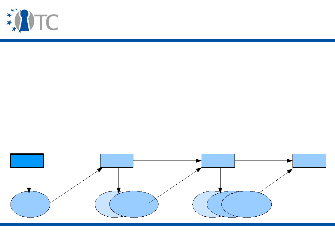
www.opentc.net
3 April 2007
52
Grid Computing (3)
• Security has been added to the Grid toolkit via the use
of a PKI:
– Virtual Organisations (VOs) are created in a chained
manner, each node creating the key pair for the next node
and extending a proxy certificate chain;
– To avoid misuse of the proxy certificates (each new node
being trusted for the recruitment of the next one), a
credential's lifetime is typically 12 hours.
CA
Alice
Proxy1
A-pubkey
cert
A-pubkey
cert
Proxy cert
for Proxy1
signs
transmit
send cred
signs
transmit
(2 creds)
send cred
transmit
(3 creds)
A-pubkey
cert
Proxy cert
for Proxy1
Proxy2
signs
Proxy cert
for Proxy2

www.opentc.net
3 April 2007
53
Daonity (1)
• Daonity is a Grid project led by HP Labs China.
• It aims at improving the Grid Security Infrastructure by
using Trusted Computing.
– At the platform level, Trusted Computing acts as an in-
platform TTP that ensures fair play between the host and
the guest by making sure that the security and
management policy are enforced.
– At the Virtual Organisation (VO) level, the certificate chain
is replaced by the migration of the VO private key and
nodes can be revoked so that they will leave the VO
without VO information.
• Each Virtual Organisation (VO) member has a TPM.

www.opentc.net
3 April 2007
54
Daonity (2)
• The Grid PKI model is modified so that:
– Chained proxy certificates are avoided;
– A small constant number of certificates are exchanged
between participants and verified by each participant;
– Credentials are protected by the TPM, thus removing the
need for a short lifetime;
– Credentials are migrated using the TCG migration protocol;
– Credential use requires explicit approval of an Online
Certificate Revocation Authority (OCRA) which is instructed
of the revocation status of a particular TPM by the VO
initiator (Alice).

www.opentc.net
3 April 2007
55
Daonity (3)
• The TSS and Daonity components are measured and the
measurements stored into PCRs. The VO key is sealed to
these measurements. This provides behaviour
conformity:
– Proxies ask the OCRA's explicit approval before using the
VO credential;
– VO participants enforce the VO policy which is controlled
by the VO initiator (Alice) and specifies how VO
information can be used (e.g. conversations saved in
cleartext).
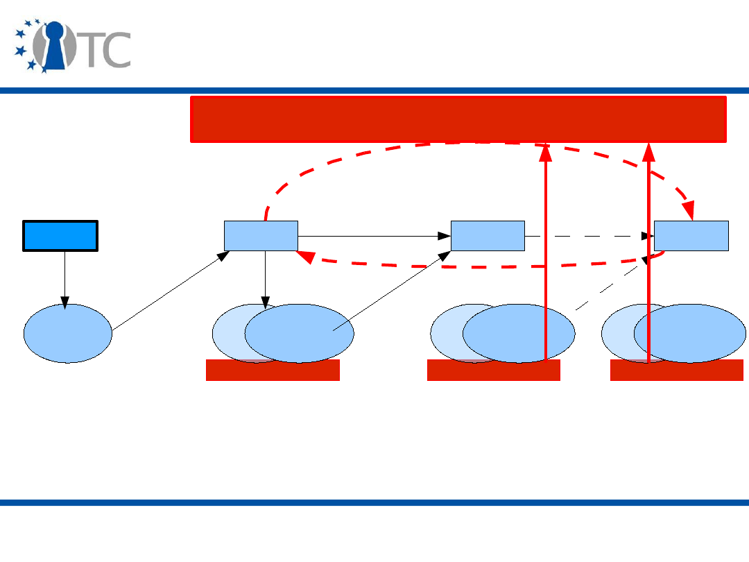
www.opentc.net
3 April 2007
56
TPM
TPM
Daonity (4)
CA
Alice
Proxy
A-pubkey
cert
A-pubkey
cert
VO-pubkey
cert
signs
transmit
migrate proxy cred
VO-privkey
signs
transmit
migrate ...
transmit ...
A-pubkey
cert
VO-pubkey
cert
Proxy
Online Certificate Revocation Authority (OCRA)
revoke
informs
explicit
approval
• The VO initiator (Alice) migrates the VO credential (VO-pubkey cert) to
the new proxies in the VO, is informed of the proxy platform state and
controls the VO policy.
• Each proxy asks the OCRA for its revocation status before using the
VO credential, and the VO initiator (Alice) can revoke proxies.
TPM
A-pubkey
cert
VO-pubkey
cert

www.opentc.net
3 April 2007
57
Daonity (5)
• Drawbacks of the approach:
– There is a lot of communications with the OCRA, but the
amount of communication can be reduced by authorising
that a VO node does not check the OCRA for a certain
period of time;
– Proxy code runs on the grid middleware (Globus toolkit)
using the TSS, but OS code can break the behaviour
conformity.

www.opentc.net
3 April 2007
58
Future Grid Systems using Trusted
Computing
• One component currently missing in Grid systems is
virtualisation.
– Trusted Virtualisation will “repair” the chain of trust at the
OS level.
– Compartmented security (and privacy) is readily available.
– Bonus: compartment management and migration.
• But efficiency constraints mean that designers need to
look carefully at the number of interactions needed.
– Example: attestation.
– Solution: offline scalable attestation, decomposed into
attestation token creation by an attestation service and
freshness verification.

www.opentc.net
3 April 2007
59
Peer-to-Peer Computing (1)
• Peer-to-Peer (P2P) Computing assumes no centralised
control and all the peers contribute equally to the P2P
network.
– Control is decentralised, but management may not be.
– Some P2P systems promote certain nodes to “super-
nodes”.
• P2P systems provide:
– Scalability;
– Availability;
– Fault-resilience.
• In P2P systems, there is a tradeoff between privacy
(pseudonymity) and access control/accountability.

www.opentc.net
3 April 2007
60
Peer-to-Peer Computing (2)
• Until now, security was not a primary concern.
– Threat was more on the authenticity of the shared content
and the legality of accessing it.
• As the technology emerges as a commercial proposition
for network storage and content distribution, security
becomes paramount.
– Availability
• DoS;
• Free-riding;
– Accountability;
– Pollution;
– Sybil attack;
– Distributed access control.

www.opentc.net
3 April 2007
61
Peer-to-Peer Computing (3)
• Trusted Computing can help through privacy-friendly
features, yet ensuring strong authenticity and integrity.
• Identity authentication protects against spoofing and
man-in-the-middle attacks.
• Integrity ensures that fair policies can be enforced.
• Attestation helps build reliable connections.
• DAA can be used to provide certified pseudonyms.
– Pseudonyms can be generated from the P2P network
identifier and the secret used during DAA-Join (
f
), and
authenticated by DAA-Sign on a predefined message.
– This message could include parameters for establishing a
session key.
– Access control can be implemented via the DAA issuer.

www.opentc.net
3 April 2007
62
Other TC-augmented applications
• Some SSL implementations make use of the TPM:
– Mutual authentication can be used, because the client has a
certified public key;
– The TPM generates a key pair whose protection reinforces
the strength of the SSL tunnel;
– The SKAE (Subject Key Attestation Evidence) extension is
used for the creation of an X.509v3 certificate for this key;
– The key is then used to sign the MD5 hash of the SSL
handshake messages and the X509v3 certificate is provided;
– The SSL client can then reuse the key for future
communications with the SSL server;
– There are many other ways to manage the SSL key, for
example to ensure pseudonimity.
• IPsec can similarly benefit from Trusted Computing.

www.opentc.net
3 April 2007
63
Integrity Measurement Architecture (1)
• Integrity Measurement Architecture (IMA) is a system
proposed by IBM to:
– Look at the integrity problem after the boot and once the
OS is started;
– Extend the attestation mechanism to a
measurement list
that is protected by the TPM.
• Integrity Measurement Architecture (IMA) assumes that
all components up to the bootloader have been
measured by the platform. The bootloader measures the
kernel which measures changes to itself and user-level
processes, which themselves can in turn measure their
inputs and sensitive data.

www.opentc.net
3 April 2007
64
Integrity Measurement Architecture (2)
• The measurement list contains the names of the files
that are measured (kernel modules, system files, TSS).
– Dirty flags are used to indicate files that may have
changed, combined with a cache of measurements.
• IMA is built around two components:
– A Measurement Mechanism determining what to measure,
when to measure it and how to securely maintain the
measurements;
– An Integrity Challenge/Validation Mechanism that allows a
remote challenger to retrieve and verify measurements.
• The Measurement Mechanism is initiated by
Measurement Agents that store the measurements of
particular files in an ordered list in the OS kernel, and
store the measurements into a PCR.

www.opentc.net
3 April 2007
65
Integrity Measurement Architecture (3)
• The Integrity Challenge/Validation Mechanism proceeds
as follows:
– The challenger sends a challenge request with a nonce to
the Attestation Service (AS) running on the attesting
system;
– The AS loads an AIK, requests a Quote from the TPM,
which signs the PCR values and the nonce with the AIK,
and retrieves the measurement list (ML) from the kernel;
– The AS sends a challenge response composed of the
signed PCR values and the ML;
– The challenger first retrieves and verifies the AIK
certificate, then verifies the signature and the freshness
(nonce), and finally that the PCR values correspond to
measurements of the files indicated in the ML.

www.opentc.net
3 April 2007
66
Integrity Measurement Architecture (4)
• Validation of the verified measurements is done by the
challenger based on:
– A list of trusted measurements;
– An interpretation of the list of measurements, e.g.
program updates, fingerprints policy.
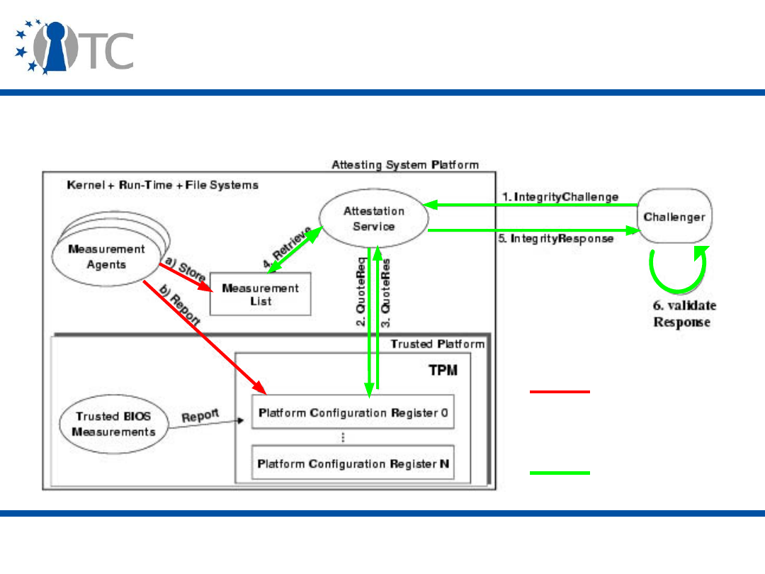
www.opentc.net
3 April 2007
67
Integrity Measurement Architecture (5)
• Integrity Measurement Architecture
Measurement
mechanism
Integrity
Challenge/
verification

www.opentc.net
3 April 2007
68
Trusted Computing-specific applications
and middleware (1)
• Enforcer is one of the first Trusted Computing
applications implemented. It implements an
authenticated boot process in Linux using the TPM.
• TrouSerS (IBM) is a Free Open-Source (FOSS)
implementation of the TSS.
– It supports only the TPM/TSS 1.1b specification, but it can
be patched to run on a TPM v1.2.
• Front-ends to Trusted Computing functionalities: TPM
tools and TPM Manager.
• BerliOS's TPM emulator for Linux.
– See previous lectures.

www.opentc.net
3 April 2007
69
Trusted Computing-specific applications
and middleware (2)
• HP ProtectTools Embedded Security is installed by
default on HP notebooks with a TPM and enables to:
– Take ownership of the TPM, clear the TPM, create and
manage keys;
– Encrypt secrets (password, fingerprint) to TPM keys;
– Manage credentials, specify policies, backup and migrate
them (and tool configuration).
• IBM (Lenovo) also provides Client Security Software in
addition to TrouSerS.
• TrustedJava aims at using Trusted Computing in the
context of Java:
– jTSS Wrapper to access TSS native code from Java (Tspi);
– JTpm, a set of command line tools for basic interaction
with the TPM and the TSS.

www.opentc.net
3 April 2007
70
Trusted Computing-specific applications
and middleware (3)
• More applications and software here:
http://www.tonymcfadden.net/tpmvendors.html#software

www.opentc.net
3 April 2007
71
Software and network security
• In order to provide “trustworthy” systems, applications
will not only have to be secured, but also be secure:
– Software quality;
– Verified software.
• See IY5607 Software Security for more details.
• Trusted Network Connect (TNC) addresses network
security in the Trusted Computing world, but it is still in
its infancy.

www.opentc.net
3 April 2007
72
Conclusion
• Although applications will transparently benefit from
Trusted Computing (integrity), direct use of Trusted
Computing will also bring benefits to the users.
• Many applications are already Trusted Computing-
aware, but much more needs to be done.
– First implementations can reveal underlying problems,
possibly requiring changes to parts of the specifications or
platforms.
– Applications are related to other aspects of trust, e.g.
legal, economic (see last lecture).
• Next: Technologies and Approaches related to Trusted
Computing.

www.opentc.net
3 April 2007
73
References (1)
• The TSS: TPM Software Stack (TSS) Specifications,
https://www.trustedcomputinggroup.org/specs/TSS/
• DAA: Ernie Brickell, Jan Camenisch and Liqun Chen. The
DAA scheme in context. In Chris Mitchell ed., Trusted
Computing, 2005, IEE Press, pp. 143-174.
• Windows Vista BitLocker
– BitLocker Drive Encryption: Technical Overview,
http://technet.microsoft.com/en-
us/windowsvista/aa906017.aspx
– Windows Vista BitLocker Client Platform Requirements,
http://www.microsoft.com/whdc/system/platform/hwsecurit
y/BitLockerReq.mspx
–
http://en.wikipedia.org/wiki/BitLocker_Drive_Encryption

www.opentc.net
3 April 2007
74
References (2)
• DRM
– Andrew Cooper and Andrew Martin. Towards an Open,
Trusted Digital Rights Management Platform. In
Proceedings of the ACM workshop on Digital rights
management (DRM '06), pages 193-206, 2006.
– Löhr et al. Enhancing Grid Security Using Trusted
Virtualization. In Proceedings of the Second Workshop on
Advances in Trusted Computing (WATC'06), 2006.
• Grid computing
– Wembo Mao, Fei Yan and Chunrun Chen. Daonity—Grid
Security with Behaviour Conformity from Trusted
Computing. In Proceedings of the 1
st
ACM Workshop on
Scalable Trusted Computing (STM'06), pages 43-46, 2006.

www.opentc.net
3 April 2007
75
References (3)
• Peer-to-Peer computing
– Shane Balfe, Amit D. Lakhani and Kenneth G. Paterson.
Securing peer-to-peer networks using trusted computing.
In Chris Mitchell ed., Trusted Computing, 2005, IEE Press,
pages 271-298.
– X. Zhang, S. Chen and R. Sandhu. Enhancing Data
Authenticity and Integrity in P2P Systems. IEEE Internet
Computing, vol. 9, no. 6, Nov.-Dec. 2005.
• TC-specific applications and middleware
– TrouSerS:
http://trousers.sourceforge.net/
– IMA: Reiner Sailer et al. Design and Implementation of a
TCG-based Integrity Measurement Architecture. In
Proceedings of the 13
th
Usenix Security Symposium, pages
223-238, 2004.

www.opentc.net
3 April 2007
76
The information in this document is provided “as is”, and no guarantee or
warranty is given that the information is fit for any particular purpose.
The user thereof uses the information at its sole risk and liability.
The Open-TC project is co-financed by the EC.
If you need further information, please visit our website
www.opentc.net or contact the coordinator:
Technikon Forschungs- und Planungsgesellschaft mbH
Richard-Wagner-Strasse 7, 9500 Villach, AUSTRIA
Tel.
+
43 4242 23355 – 0
Fax.
+
43 4242 23355 – 77
Email coordination@opentc.net
Open_TC EC Contract No: IST-027635

Technologies and Approaches related to
Trusted Computing
Stéphane Lo Presti
Royal Holloway, University of London
Stephane.Lo-Presti@rhul.ac.uk

www.opentc.net
3 April 2007
2
Introduction
• Trusted Computing is a reality today through the TCG's
specifications and its members' products.
• But this concept did not start with the TCG, and goes
beyond the topics addressed by the TCG.
• We will now give a broader overview of trusted
computing, introducing the following systems:
– XOM;
– AEGIS;
– PERSEUS;
– Terra;
– The IBM 4758 Processor.

www.opentc.net
3 April 2007
3
XOM
• XOM (eXecute Only Memory) is a system created at
Stanford University (USA).
• The initial aim was to prevent users examining
executable code by providing memory than can only be
executed, but the scope was later expanded to prevent
the execution of unauthorised code.
• The challenge was to use an untrusted OS to manage
trusted hardware.
• A XOM machine supporting internal integrity- and
confidentiality-protected compartments is proposed.

www.opentc.net
3 April 2007
4
XOM Model (1)
• Memory and OS are not trusted.
– OS performs only resource management.
– OS can only perform denial-of-service attacks against its
applications.
– Values stored in on-chip memory and registers are in
clear, while values stored in off-chip memory are
encrypted, along with the memory location of programs
accessing them and a hash of the values.
• The XOM processor possesses its own asymmetric key
pair, special memory used for its functioning, and a
special privileged execution mode.
• It also implements a special set of instructions used for
protecting programs and memory.

www.opentc.net
3 April 2007
5
XOM Model (2)
• Hardware support for symmetric encryption and
decryption, and MACing, is needed for acceptable
performance.
• The XOM functionality can be implemented in hardware,
or also use a Virtual Machine Monitor (VMM).

www.opentc.net
3 April 2007
6
XOM Virtual Machine Monitor (1)
• XOM prevents programs from tampering with each other
by placing them in separate compartments.
– OS runs in a separate compartment.
– OS should be able to manage resources without having to
interpret data values in transit.
– OS cannot read or modify process data.
• A XOM Virtual Machine Monitor (XVMM) creates and
manages the compartments.
– The XVMM is implemented either in hardware (microcode)
or in software. A software XVMM must be secure-booted.
– It is the only element authorised to access the processor
key pair and the special memory.

www.opentc.net
3 April 2007
7
XOM Virtual Machine Monitor (2)
• The XOM processor runs the XVMM in a privileged mode
so that it can trap to the XVMM on cache misses.
• A NULL compartment is used to execute unencrypted
code.
• The XVMM can save instructions to the instruction cache
(decrypt instructions that are encrypted, and check their
hash values), but it cannot save program data to the data
cache as there is no way to differentiate between data
types (shared, private) without additional hardware
extensions.
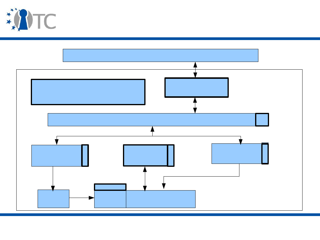
www.opentc.net
3 April 2007
8
XOM Architecture
Main memory
Symmetric
Decryption Unit
XOM Asymmetric Decryption
Microcode and Key
L2 Cache
L1 Instruction
Cache
L1 Data
Cache
Private
Memory
Register
File
Datapath
Decode
XOM
ID
Tags
XOM
ID
Tags
XOM ID Tags
XOM ID
Tags and
Valid bits
Private
Key

www.opentc.net
3 April 2007
9
XOM Services (1)
• XOM provides three services:
– Decryption of the symmetric session key used to protect a
program with the asymmetric key pair embedded in the
XOM machine;
– Decryption of the program code using the session key;
– Isolation of the principals (code and their data) and
ensuring a strictly controlled information flow.
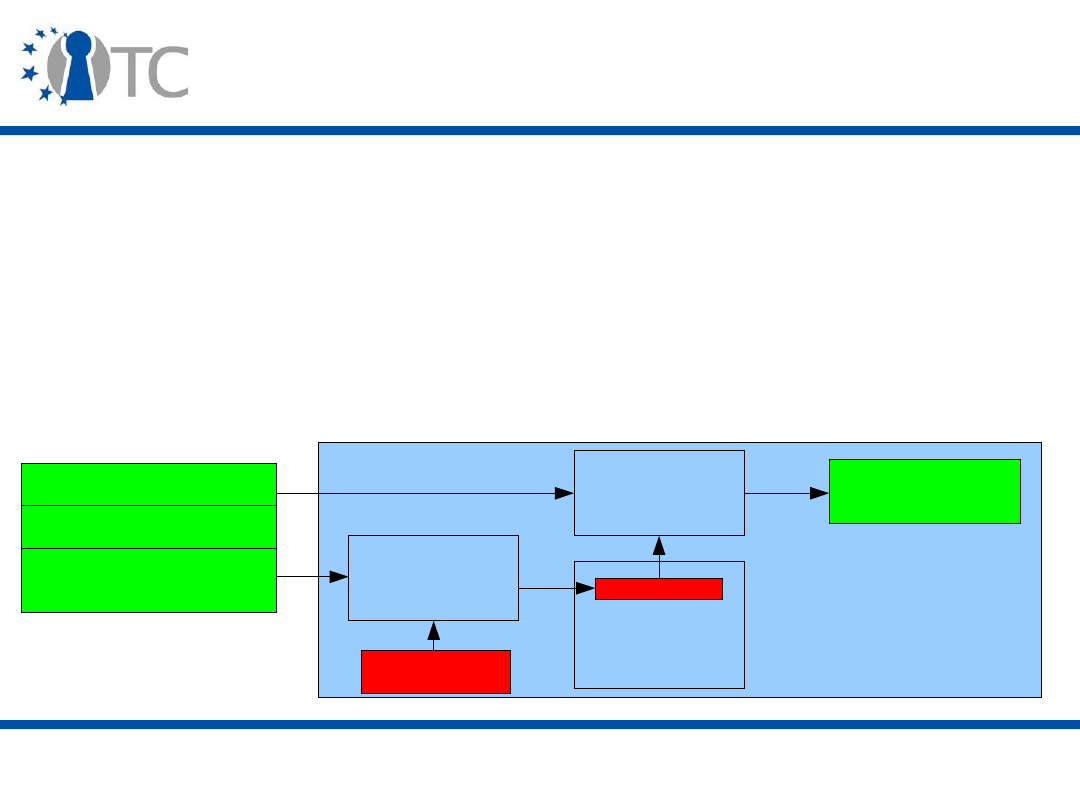
www.opentc.net
3 April 2007
10
XOM Services (2)
• The program code is sent by a service provider
symmetrically encrypted, with the key encrypted with
the XOM machine key
– The originally proposed XOM algorithm does not include
integrity-protection, e.g. a MAC.
• Once on the XOM machine, its verification and
decryption are handled transparently.
Unencrypted code
Encrypted code
Encrypted Symmetric
Key
Main memory
XOM processor
Private key
Asymmetric
Decryption
Module
XOM
Key table
Asymmetric
Decryption
Module
Executable
code

www.opentc.net
3 April 2007
11
XOM Services (3)
• A XOM ID register records the XOM identifier of the
active principal and is used to:
– Check the ID tags attached to registers and cache lines;
– Attach the active principal's XOM identifier to data that it
produces.

www.opentc.net
3 April 2007
12
XOM key table
• XOM key table associates the decrypted key with a XOM
identifier.
• It is updated by the XOM Virtual Machine Monitor
(XVMM) each time a compartment is created,
interrupted or deleted.
• Actually the XOM key table is composed of two
subtables:
– The Register Key table associates keys for decrypting
registers with XOM identifiers;
– Compartment Key table maps keys for decrypting cache
lines with XOM identifiers;
– Multiple register keys may point to the same entry in the
Compartment Key Table in order to allow multiple
instances of the same program to execute.

www.opentc.net
3 April 2007
13
Private data
• Data is decomposed into:
– Shared data (which comprises data from NULL
compartment);
– XOM program private data that needs to be integrity- and
confidentiality-protected when evicted from the cache.
• During interrupts or context switching, the XOM Virtual
Machine Monitor (XVMM) must flush instruction cache
and clear registers.
– Shadow registers are used to save register values, and
keep track of the data status (shared, private) and the
compartment ownership.
• On-chip memory stores tagged shadow registers used
for the various compartments, and the XOM key table.

www.opentc.net
3 April 2007
14
XOM Instructions (1)
• XOM provides eight new instructions (possibly via the
XVMM):
–
enter_xom
is used for the decryption of the compartment
key and the program code and data; one parameter also
indicates the cache miss handler and the interrupts trap;
• Hardware XVMM shunts this redirection and improves the
performance of managing cache and interrupts;
–
exit_xom
restores handlers changed by
enter_xom
;
–
secure_store
moves data from private registers to data
cache then to external memory, protecting the data by
MACing and encrypting it;
• Shadow registers are set to private;
–
secure_load
imports values from the memory into the
registers, if the MAC verification succeeds;

www.opentc.net
3 April 2007
15
XOM Instructions (2)
–
move_from_shared
and
move_to_shared
change the
shadow register information between shared and private;
–
save_register
moves register values that are private to
the shadow registers, while keeping a record of the source
register;
–
restore_register
restores the values stored in the
shadow register to the source register.

www.opentc.net
3 April 2007
16
XOM Functionalities (1)
• To provide its services, XOM has three functionalities:
– Secure storage;
• XOM compartment ID is used to enforce data access;
•
secure_load
and
secure_store
instructions are used to
move data;
•
move_to_shared
and
move_from_shared
instructions are
used to keep track of data status;
– External memory protection;
• Data is tagged with the XOM compartment ID, MACed, and
encrypted with the compartment key;
• A secure hash of values stored in external memory is kept
on-chip to protect against replay attacks;
– Security over interrupts;
•
save_register
and
restore_register
instructions are used
to manage registers during interrupt handling.

www.opentc.net
3 April 2007
17
XOM Functionalities (2)
• Other functionalities have been added to XOM via a
dedicated OS (XOMOS, based on the Unix system IRIX):
– System calls for executing the XOM instructions in user-level
applications;
– Virtual Key table in order to enable more processes to run in
parallel;
– Paging support ensuring efficient access to hash values;
– Dynamically linked libraries cannot enter a compartment, so
they are executed unencrypted (untrustworthy), but code
compiler must modify the calling convention (caller in the
compartment is the only one able to access the registers);
– User-defined signal handlers are used to access the state of
interrupted processes; they must use the register key to
access process information and so must be associated with
the compartment.

www.opentc.net
3 April 2007
18
AEGIS
• AEGIS is a system created at the Massachusetts Institute
of Technology (USA).
• It provides a processor architecture that protects
applications against physical and software attacks.
• Memory and other components do not have to be
modified.
• Side-channel attacks are always possible.
• Initially, AEGIS had two implementations depending on
whether or not the OS has a trusted security kernel.
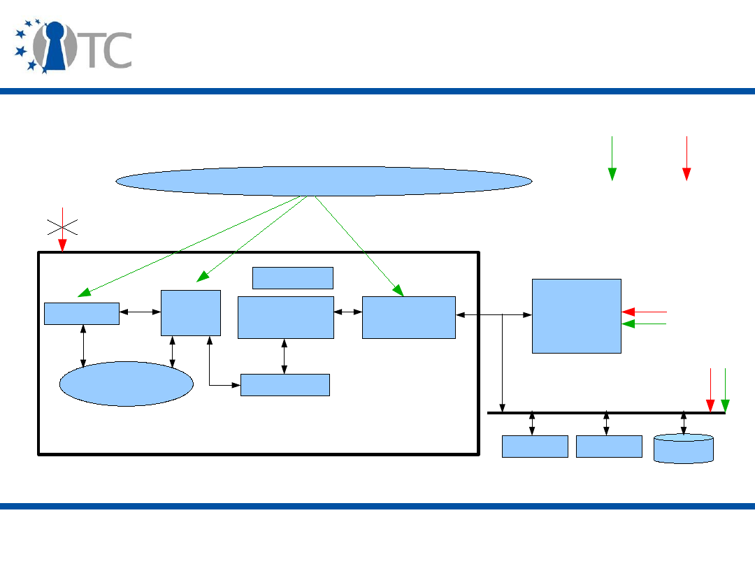
www.opentc.net
3 April 2007
19
AEGIS General model and architecture
(1)
Cache
Registers
Encryption
Integrity
Verification
Untrusted
Memory
Untrusted part of the OS. Malicious applications.
Security
Kernel
Keyboard
Display
Disk
AEGIS Processor
Software
Attack
Hardware
Attack
Memory
Controller
Keyboard
Hash cache

www.opentc.net
3 April 2007
20
AEGIS General model and architecture
(2)
• The AEGIS processor has a physical RNG and a certified
key pair.
– New instructions:
l.secure.*
(
enter
,
exit
,
suspend
,
resume
,
csm
) and
l.puf.*
(
response
,
secret
).
– A private key stored either in EEPROM (Non-Volatile
memory) or fuses can still be physically attacked. PUFs
(Physical Unclonable Functions) are used instead.
• AEGIS provides two types of execution environment:
– Tamper-Evident (TE), where physical and software
tampering is guaranteed to be detected;
– Private Tamper-Resistant (PTR), where, in addition to
detection of tampering, an adversary cannot gain any
information by tampering with or observing the system
operation.

www.opentc.net
3 April 2007
21
Secure Context Manager
• A Secure Context Manager (SCM) is used when no
security kernel exists. The SCM manages the programs
running in the AEGIS mode by assigning Secure Process
ID (SPID) and maintaining a process table:
– Each table entry is composed of: SPID, program hash,
register values, hash for memory integrity verification,
tamper-evident/resistant bit, two encryption keys (static,
dynamic);
– The
l.secure.enter
and
l.secure.exit
instructions
create and delete table entries.
• The SCM is stored in memory, and cached in the AEGIS
on-chip cache.
– Movement of cache entries is protected by encryption with
a processor master key.

www.opentc.net
3 April 2007
22
Memory protection (1)
• The Memory Management Unit (MMU) is modified so that
memory can be partitioned into two regions:
– Integrity Verification (IV);
– Memory Encrypted (ME).
• Furthermore, data is separated into static (application
instructions) and dynamic (heap, stack) data.
– Static corresponds to read-only and can be IV protected
simply by a MAC.
• ME done using a One Time Pad (OTP) encryption scheme.
– Evicted cache block is XORed with AES encryption of its
memory address, a timestamp and a constant vector.

www.opentc.net
3 April 2007
23
Memory protection (2)
• The memory protection depends on where the data is:
– On-chip cache:
• Physical attacks are not relevant, but software ones still are;
• SPIDs and address checks are used to protect against these
attacks;
• If the security kernel is available, virtual memory and
privileges add to the protection.
– For Off-chip memory, data transferred from on-chip has to
be integrity protected:
• Integrity verification between L2 cache and encryption module
• Merkle/Hash trees used by each process to protect dynamic IV
memory
– Parent hash=concatenation of its children;
– Root stored securely in the SCM;
– Verification from children to parent until root or node in the cache.

www.opentc.net
3 April 2007
24
Processor security modes (1)
• The AEGIS processor can be run in four security modes:
– Standard (STD) and Suspended Secure Processing (SSP) mode
• Access to unprotected memory;
• Unprotected code execution;
• Switch to the two other modes (TE and PTR);
• STD can manage Virtual Memory, but not SSP;
• SSP mode used by a program running in TE or PTR to execute
insecure code;
• No STD or SSP processes can access IV or ME protected memory
regions.
– Tamper-evident (TE)
• Access to verified memory.
– Private Tamper-resistant (PTR)
• Access to private memory, and can use the
l.puf.*
instructions.

www.opentc.net
3 April 2007
25
Processor security modes (2)
• The Tamper-evident (TE) mode, which protects of the
program initial state, is started by the
l.secure.enter
instruction:
– A hash of the program code is obtained and stored in
protected storage;
– The program must then check hashes of programs it uses;
– The execution environment is then checked.
• Processor mode, data stack, virtual address.
• Protection of the program from interrupts is done by
preserving the registers over an interrupt.
• Either done by the SCM or the security kernel.

www.opentc.net
3 April 2007
26
Processor security modes (3)
• The PTR mode is launched via the
l.secure.csm
instruction.
– Then a static key and the program hash are encrypted
under the aegis public key.
• With a hash of the security kernel (if available).
– All registers are private and protected and can only be
used by processes with the corresponding access rights.
– The second Most Significant Bit (MSB) of the virtual
address determines if information exported to off-chip
memory has to be protected.
– When an interrupt occurs, the register values are securely
saved, the registers are cleared, and then restored after
the interrupt handler finishes.

www.opentc.net
3 April 2007
27
Processor security modes (4)
– On-chip memory can only be accessed if SPID of memory
cache matches the one of the active process, that must be
in PTR mode.
• If a security kernel is running, virtual memory and privileges
are also checked.
– For off-chip memory, a hardware engine is added between
the integrity checker and the memory bus.
• Information is symmetrically encrypted when leaving the on-
chip memory with the static key specified in the
l.secure.csm
instruction (protected by the processor key);
• A dynamic key is used to protect data generated during
program execution (randomly chosen);
• During process switches, the security kernel must save and
clear the static key of interrupted process.

www.opentc.net
3 April 2007
28
Processor security modes (5)
• The processor stores SM and UM bits to track the
security mode in supervisor and user processor mode.
• The TE and PTR modes protect against tampering at
various stages of the program execution:
– Initial state, using a hash function;
– On-chip cache and off-chip memory;
– State information during interrupt or context switch.
• During program execution, Integrity Verification (IV),
Memory Encryption (ME), and access permission checks
via secure execution modes are used;
– Transitions between secure execution modes are
monitored so that execution protection cannot be
circumvented.
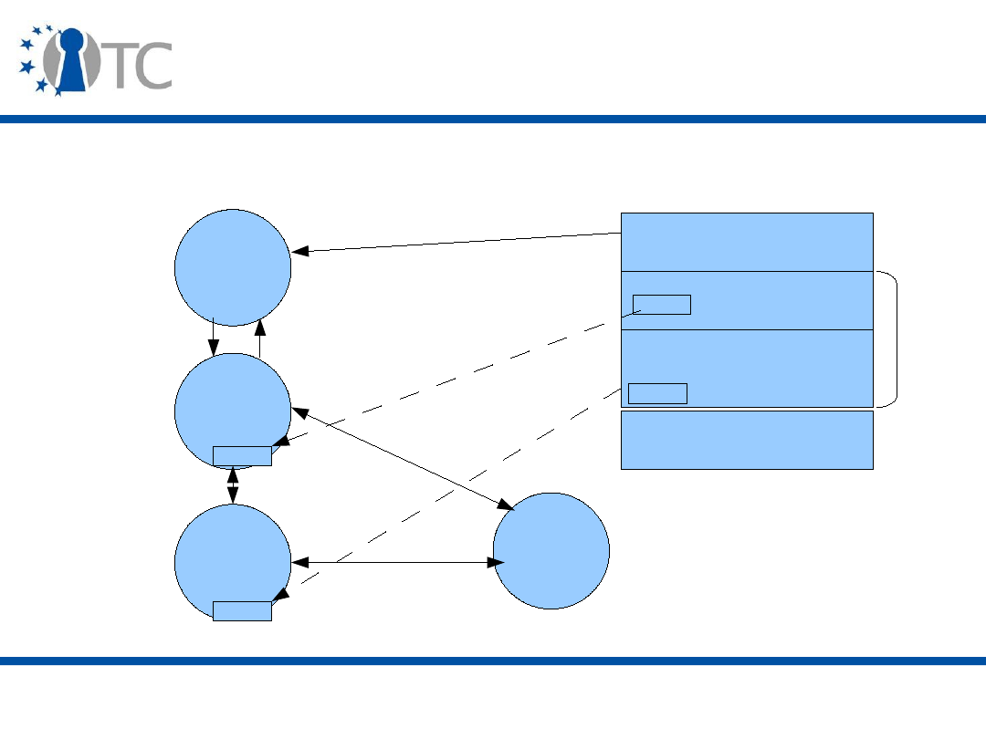
www.opentc.net
3 April 2007
29
Processor security modes (6)
Bootstrapping
Private code
Untrusted code
STD
Mode
TE
Mode
PTR
Mode
SSP
Mode
trusted
VMM
VMM
• Security modes can only transition in a particular order:
l.secure.enter
l.secure.exit
l.secure.csm
l.secure.suspend
/resume
l.secure.suspend
/resume

www.opentc.net
3 April 2007
30
Physical Unclonable Functions (1)
• Physical Random Functions (PRFs), also called Physical
Unclonable Functions (PUFs), are functions that map a
set of challenges to a set of responses based on an
intractably complex physical system.
– Example: silicon hidden timing and delay information.
– They are used to create new secrets and securely store
them.
– Hashing the PUF output prevents building a model of the
PUF.
• The PUF is accessible via the AEGIS processor
instruction
l.puf.response
.

www.opentc.net
3 April 2007
31
Physical Unclonable Functions (2)
• The actual PUF challenge is a hash of the concatenation
of the pre-challenge sent by the security kernel and the
hash of the security kernel, to prevent a malicious
security kernel from learning the response for a
particular challenge.
–
l.puf.response(H(SK_hash || preC))
–
H
is a cryptographic one-way hash function
• Because PUF outputs can be slightly different for the
same input, due to environmentnoise, error correcting
codes must be added to obtain the same secret after
every evaluation.

www.opentc.net
3 April 2007
32
Physical Unclonable Functions (3)
• Similarly to the previous scheme, a user-level
application secret can be created.
• Once a user knows a challenge-response, he can share a
secret with the security kernel:
– This is facilitated by the processor instruction
l.puf.secret
which, for a challenge C, returns:
H(SK_Hash || l.puf.response(C))
– The security kernel then in turn returns:
H(App_hash ||
l.puf.secret(C))
• The AEGIS security kernel exposes the AEGIS processor
instructions
l.puf.response
and
l.puf.secret
to the
user-level applications via equivalent system calls.

www.opentc.net
3 April 2007
33
Program results signing and
communication
• Result from program execution can be signed with the
sign_msg
instruction (or its equivalent system call if a
secure kernel is available).
• The signature over the result is concatenated with the
program hash.
– And the security kernel hash (if available).
• The XOM architecture does not enable two
compartments to directly exchange information.
– Instead, this must be done through the NULL
compartment, and communication security must be
ensured via other means.

www.opentc.net
3 April 2007
34
AEGIS support for Programming
Languages
• Programming language constructs were added to access
the AEGIS features:
– Data or functions are either unprotected, verified, or
private.
• Unprotected functions execute in STD or SSP modes with
access to only unprotected data.
• Verified functions execute in TE or PTR mode depending on
which variable they access.
• Private functions execute encrypted in PTR mode.
– There are three corresponding separate stacks, heaps and
memory spaces for storing instructions.
• A trusted compiler is necessary to create trusted
programs.

www.opentc.net
3 April 2007
35
PERSEUS
• PERSEUS was developed in Germany (IBM, Saarland,
Karlsruhe)
• More emphasis in this work on the social acceptability of
the system by demonstrating a trusted system that is
both controlled by the user and enforces a provider's
policy.
– See last lecture.
• PERSEUS is built on top of trusted hardware and
provides:
– Open-Source and lightweight system (portable or mobile
platforms) that is compatible with Linux;
– A layered design.
• PERSEUS formed the basis of the EMSCB system.
– See previous lecture.

www.opentc.net
3 April 2007
36
PERSEUS Architecture
• PERSEUS is built around a minimal security kernel that
runs OSs.
– L4 microkernel provides the basis of the PERSEUS security
kernel: it implements address spaces, inter-process
communication and scheduling, all other services being
run in user mode;
– A Virtual Machine Monitor (VMM) can also be used as a
basis (Xen);
– In addition to the previous, added components include:
• Resource and memory managers to enforce policies;
• Device drivers with DMA isolation;
• Trusted I/O paths and User Interface components;
• Secure application and storage managers.

www.opentc.net
3 April 2007
37
PERSEUS Trustworthiness
• PERSEUS code is less than 100 kLOC (Lines Of Code).
– Decreases significantly the probability of software bugs.
– Open-source nature may increase trust (see IY5607
Software Security).
• PERSEUS enforces policies, including DMA restrictions.
• It can use TCG components or execute legacy systems
in an unaffected way.
• Applications implemented include:
– Secure boot;
– Digital Rights Management (DRM);
– Authenticated Digital Signing of documents viewed in a
secure way, possibly using Smartcards.
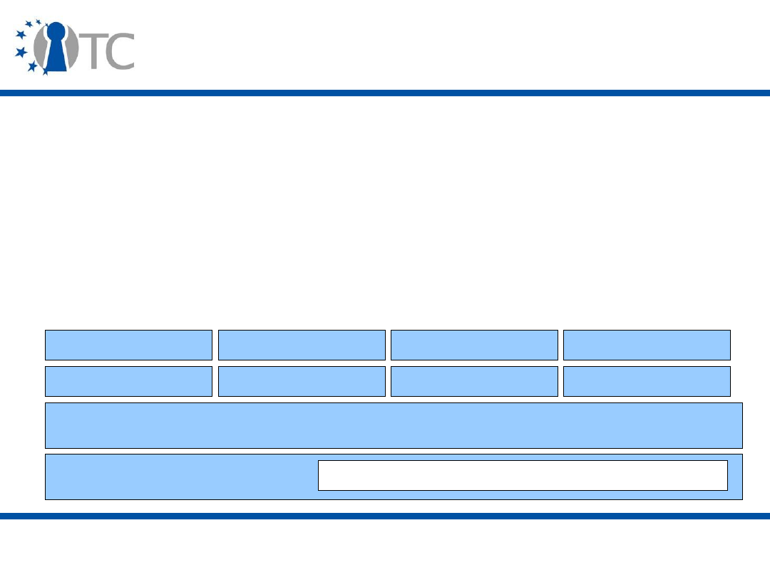
www.opentc.net
3 April 2007
38
Terra (1)
• Terra was created at Stanford University (USA) and
aimed at strengthening peer authentication in order to
secure distributed applications.
• Terra provides a Virtual Machine (VM)-based platform.
– “Open” or “Closed” boxes.
• Built on top of a TVMM (Trusted Virtual Machine
Manager).
TVMM
Thin OS
Commodity OS Commodity OS
Thin OS
Management VM
Email, web
Distrib. Comp.
Online game
Hardware
Attestation and Sealed Storage Device

www.opentc.net
3 April 2007
39
Terra (2)
• Terra operates an authenticated boot in the usual way:
– Private key embedded in hardware, signed by manufacturer;
– Hardware certifies firmware;
– Firmware certifies bootloader;
– Bootloader certifies Trusted Virtual Machine Monitor (TVMM);
– TVMM certifies VMs.
• A component wanting to be certified:
– Generates a public/private key pair;
– Makes an ENDORSE API call to a lower level component;
– Lower level component generates and signs a certificate
containing:
• A SHA-1 hash of attestable parts of higher component;
• Higher component’s public key and application data.

www.opentc.net
3 April 2007
40
Terra (3)
• TVMM provides:
– Isolation;
– Extensibility/Compatibility;
– Efficiency;
– Security
• TVMM outside of OS administrator control;
• Attestation;
• Trusted path.
• Attestation of VMs can be done in two ways:
– Ahead-of-Time, for small, high-assurance VMs that are
hashed just after the boot process;
– Optimistic, for larger VMs that are hashed block by block
while the blocks are loaded during execution.

www.opentc.net
3 April 2007
41
Terra (4)
• Since one of the initial usage scenario for Terra is
Trusted Quake (video game), the problem of device
drivers is important:
– Large and complex software;
– Inherently insecure (OS spying).
• Terra requires hardware support to solve this problem.

www.opentc.net
3 April 2007
42
Terra (5)
• Terra also provides Trusted Access Points (TAPs) to
check communications only.
– A client VM includes VPN client and firewall, and enforces
the application's communication policy.
– A TAP gateway bridges the internal network to the
restricted one.
– Client and server mutually-authenticate.

www.opentc.net
3 April 2007
43
The IBM 4758 Processor
• The 4758 is an IBM tamper-responsive, general purpose,
secure coprocessor.
– Tamper-responsive: secrets are cleared and certificates
deleted in case of physical tampering (physical
penetration, power, temperature or radiation attacks).
• The PCI card can be added to any IBM PC.
• The card encapsulates a 486 processor and has a root
certificate used for attestation,
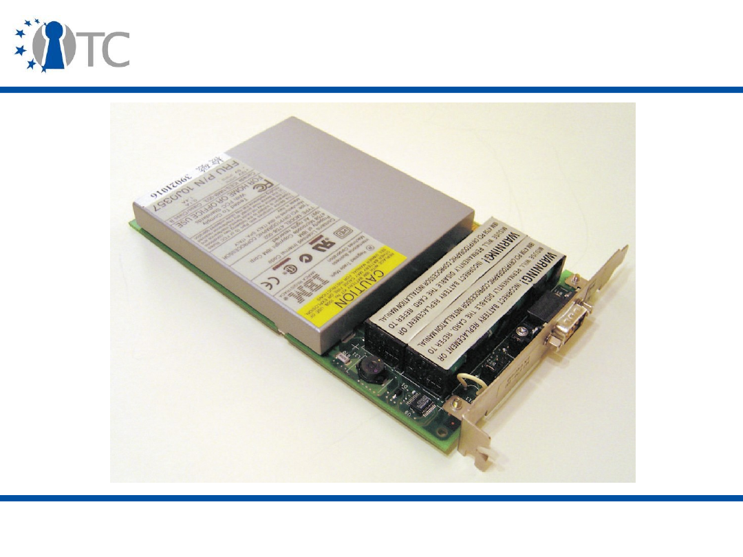
www.opentc.net
3 April 2007
44
Picture of the IBM 4758

www.opentc.net
3 April 2007
45
The IBM 4758 Software
• All software is organised into layers:
– Each layer has an owner that authorises operation on the
next layer and has a hash of the next layer;
– Layer 0 is the miniboot (firmware, owner: IBM) and
possesses a unique key with a certificate linked to IBM's
root key;
• Used to send attestation;
– Layer 1 is the boot (firmware, owner: IBM);
– Layer 2 is the OS (software, owner designated by IBM);
– Layer 3 is the user-level application (owner designated by
owner of layer 2) and is (usually) the only piece of
software that can be installed on the 4758.

www.opentc.net
3 April 2007
46
Conclusion
• The Trusted Computing approach has its roots in a
series of schemes proposed over the last ten years.
• Many systems have been proposed, and even
implemented, all modifying the hardware at one level or
another.
• Most systems seemed to converge towards similar
features:
– Physical and logical integrity protection;
– Cryptographic reinforcement;
– Control via privileged components that bridge hardware
and software.
• Next: Trust and the Future of Trusted Computing.

www.opentc.net
3 April 2007
47
References (1)
• Trusted Computing, Chris Mitchell (ed.), IEE Press.
• XOM:
– David Lie, Chandramohan Thekkath, Mark Mitchell, Patrick
Lincoln, Dan Boneh, John Mitchell, Mark Horowitz.
Architectural Support for Copy and Tamper Resistant
Software. In Proceedings of the 9
th
international
conference on Architectural support for programming
languages and operating systems, pages 168-177, 2000.
– D. Lie, C. Thekkath, M. Horrowitz. Implementing an
Untrusted Operating System on Trusted Hardware. In
Proceedings of the 19
th
ACM symposium on Operating
systems principles, pages 178-192. ACM Press, 2003.
–
http://www-vlsi.standford.edu/~lie/xom.htm

www.opentc.net
3 April 2007
48
References (2)
• AEGIS:
– G. Edward Suh, Dwaine Clarke, Blaise Gassend, Marten
van Dijk, Srinivas Devadas. AEGIS: Architecture for
Tamper-Evident and Tamper-Resistant Processing. In
Proceedings of the 17
th
Annual International Conference on
Supercomputing, pages 160 - 171, June 2003.
– G. Suh, C. O'Donnell, I. Sachdev, S. Devadas. Design and
Implementation of the AEGIS Single-Chip Secure Processor
Using Physical Random Functions. In Proceedings of the
32
nd
Annual International Symposium on Computer
Architecture (ISCA'05), pages 25-36, June 2005.

www.opentc.net
3 April 2007
49
References (3)
• PERSEUS:
– Ahmad-Reza Sadeghi and Christian Stuble. Taming
“Trusted Platforms” by Operating System Design. In
Proceedings of the international workshop on information
security applications (WISA 2003), pages 286-302, LNCS
2908, Springer, 2003.
–
http://www.perseus-os.org
• Terra: T. Garfinkel, B. Pfaff, J. Chow, M. Rosenblum, D.
Boneh. A Virtual Machine-Based Platform for Trusted
Computing. In Proceedings of the 19
th
ACM Symposium
on Operating Systems Principles (SOSP), pages 193-206,
ACM Press, 2003.

www.opentc.net
3 April 2007
50
References (4)
• THE IBM 4758 Processor:
– J. Dyer, M. Lindemann, R. Perez, R. Sailer, S.W. Smith, L.
van Doorn, S. Weingart. Building the IBM 4758 Secure
Coprocessor. EEE Computer. 34: 57-66. October 2001.
– http://www-
03.ibm.com/security/cryptocards/pcicc/overview.shtml

www.opentc.net
3 April 2007
51
The information in this document is provided “as is”, and no guarantee or
warranty is given that the information is fit for any particular purpose.
The user thereof uses the information at its sole risk and liability.
The Open-TC project is co-financed by the EC.
If you need further information, please visit our website
www.opentc.net or contact the coordinator:
Technikon Forschungs- und Planungsgesellschaft mbH
Richard-Wagner-Strasse 7, 9500 Villach, AUSTRIA
Tel.
+
43 4242 23355 – 0
Fax.
+
43 4242 23355 – 77
Email coordination@opentc.net
Open_TC EC Contract No: IST-027635

Trust and the Future of Trusted
Computing
Stéphane Lo Presti
Royal Holloway, University of London
Stephane.Lo-Presti@rhul.ac.uk

www.opentc.net
30 March 2007
2
Introduction (1)
• Trust was defined by the TCG as:
A platform can be trusted when it behaves as expected for a
particular purpose.
• The Oxford English dictionary defines trust as:
Confidence in or reliance on some quality or attribute of a
person or thing, or the truth of a statement.
• Another commonly accepted definition of trust is:
A psychological state comprising the intention to accept
vulnerability based upon positive expectations of the
intentions or behaviour of another.
• Trust is a semantically overloaded word.
– But it is a fundamental notion for understanding human
and social phenomena.

www.opentc.net
30 March 2007
3
Introduction (2)
• While the TCG's technical definition of trust is fit for the
purpose of its specifications, it may be different from the
definitions given in other domains.
• As the Trusted Computing ecosystem expands, this may
create some problems and tensions between the
ecosystem entities due to differing, and possibly
conflicting, meanings of trust.
• We will explore some dimensions of the notion of trust in
this lecture and examine some of the criticisms that
have been made regarding Trusted Computing.

www.opentc.net
30 March 2007
4
Trusted vs. Trustworthy
• The US Department of Defence was among the first to
mention trust in the security field (Trusted Computer
System Evaluation Criteria):
a
trusted
system or component is defined as one which can
break the security policy, while a
trustworthy
system or
component is one that will not fail.
– This definition of a trusted system seems counter-intuitive,
but
trusted
refers the
need
to be trusted for the system to
function, while
trustworthy
corresponds to the fact of
actually being
trusted.

www.opentc.net
30 March 2007
5
Trust decision
• The difference between
trusted
and
trustworthy
is made
by a
trust decision
, where an entity (user, program,
component) assesses the system trustworthiness
against its situation (e.g. experience, rules, goal,
context).
• In this decision, risk (amount of money of a transaction,
probability of a loss) and goal (strategy) are other
important factors taken into account.
• To be able to make a trust decision, the entity must be
able to unambiguously identify the system and get
exact information about it.

www.opentc.net
30 March 2007
6
Trust properties (1)
• Real-life trust has various complex properties.
– It can have a varying scope (trust in a general or specific
ability, blind trust). If a scope A is included in a scope B,
trusting an entity with regards to B implies trusting it with
regards to A.
– Trust is a dynamic notion that is related to time (difficult to
earn, easy to loose, lost with the passing of time and no
interaction). Trust is a process rather than a product and
develops in phases (learning). An entity whose actions
follow patterns (behaviour) is more trustworthy than one
behaving in an unpredictable manner.
– Trust is dependent on the social group the entity belongs
to (reputation, social conventions and rules). Structure of
these social groups can be complex (inclusion,
overlapping, multiple identities).

www.opentc.net
30 March 2007
7
Trust properties (2)
– Trust is dependent on the level of uncertainty
(newcomers). When all information is known, there is no
need for trust, as decisions can be made solely on the
basis of the information. Trust can be seen as an
intermediary stage between ignorance and knowledge,
and is used to reduce complexity.
– Trust is subjective, i.e. relative to the user's own point of
view (difficult to share and make objective, predisposition,
prejudices).
– Trust is not binary but can rather be quantified (discrete or
integer value). But it is often reduced to a binary decision
(trust threshold).
– Trust is not always transitive (i.e. A trusts B and B trusts C
implies A trusts C) and not always reciprocal (A may trust
B, but B may not trust B).

www.opentc.net
30 March 2007
8
The Many Facets of Trust (1)
• Economics
– Trust has many degrees and a complex evolution that can
be modelled by economic model.
– In business, trust is actually an asset to protect, as for
example people generally associate certain levels of trust
to brands (e.g. Microsoft).
– A market can be a social group and its rules determine the
context of trust.
• Social
– The reputation of someone is determined by the
aggregation of recommendations given by others.
– Society can limit the acceptability of certain behaviours
(culture).
– Social engineering is used to break security.

www.opentc.net
30 March 2007
9
The Many Facets of Trust (2)
• Legal
– Laws can remove the need for trust, for example by defining
the general conditions of success or failure of a transaction
and the litigation process.
– Contracts can increase trust between partners.
– Fairness is usually dealt with on case to case basis (e.g.
Microsoft's anti-competitive behaviour, DRM).
– Open-Source Software causes legal problems, due to its
license model and openness.

www.opentc.net
30 March 2007
10
The Many Facets of Trust (3)
• Philosophy/Psychology
– Trust is an irrational concept. People are less predictable
than programs and emotions sometimes lead them to make
trust decisions contrary to their interests.
– Technology does not define “good” and “bad”. Technology
users interpret systems to map them to their own definitions
and make a judgement, that influences trust.

www.opentc.net
30 March 2007
11
Trust and Security
• The relationship between trust and security is complex:
– In security, trust usually pre-exists security (human trust)
and is sometimes necessary (Trusted Third Party, root of
trust).
– But trust in a computing system is dependent on the level
of security. People trust systems using adequate security,
while they distrust systems using security that is too strong.
• The two properties are sometimes different in that
security does not involve a subjective judgement:
– Being malicious can break a policy, but being selfish may
not.
– To an expert, a security protocol can be very robust, but to
a non-expert the protocol robustness might depend on
his/her own experience with it (feeling of security).

www.opentc.net
30 March 2007
12
Trust and Trusted Computing
• The Trusted Computing technologies provide the means to
collect and share evidence of behaviour (platform state). An
entity then knows what
can
be trusted.
• Then particular behaviours are assessed and people agree
(in a social context, e.g. experts in BIOS, OS, VMM, or
company administrators) if the element's behaviour is
correct, good and fair (depending on the element's
function). An entity then knows what
should
be trusted.
• In Trusted Computing, trust corresponds to behavioural
reputation.
– A virus or Trojan is trusted to perform the bad operations it
was programmed to execute. More confusingly, these
operations are not always bad, e.g. the Blast.D (or Nachi)
worm cleaned the Blaster virus and applied the security patch.

www.opentc.net
30 March 2007
13
PGP's Web of Trust (1)
• The authentication systems PGP (Pretty Good Privacy) is
a public key encryption program that is used to secure
end-to-end communications (e.g. emails).
• In PGP, a certificate binds a key to a person (e.g. name
and email address).
• People assign trust values (
ultimate
,
complete
,
marginal
,
untrusted
) to the keys according to their
knowledge (how the certificate was obtained, who the
person is).
– Public keys are stored on public servers distributed among
the world.
– Trust values are stored in a local
web of trust
.

www.opentc.net
30 March 2007
14
PGP's Web of Trust (2)
• Valid keys have either an
ultimate
trust value, or are
signed by one key with
complete
trust value, or signed
by two keys with
marginal
trust value.
– Validity can be limited to a certain key chain length, and
the default number of complete/marginal keys required for
validity (respectively one and two) can be redefined by the
user.
• Users then sign (they act as a CA for the users trusting
them) the certificate of a valid key and send the
signature to the user of the key.
– Key signing parties can be organised to exchange
signatures in a group.

www.opentc.net
30 March 2007
15
PGP's Web of Trust (3)
• Possible attacks:
– Sybil attack, when an attacker uses different email
addresses to generate key signatures between his
different accounts;
– Collusion, when a group of users share their knowledge in
order to get more signatures, and thus improve their
individual trustworthiness.

www.opentc.net
30 March 2007
16
Trust Management (1)
• Trust Management Systems bind together Public Key
credentials (authentication) and policies in order to
express complex authorisation decisions:
– Given a policy P, a set of credentials {ci} and a request
for a resource R, the problem is to determine if R satisfies
P with {ci} and, if not, possibly indicate the missing
elements;
– The policy is not necessarily centralised, it can be
distributed among various systems, and it may specify
how to find missing information in order to decide
whether to accept or reject a request;
– The cryptographic aspects are generally taken for granted
(integrity check, signature validation).

www.opentc.net
30 March 2007
17
Trust Management (2)
• Trust Management policy languages are usually
specified as a list or set of assertions, i.e. policy (access
right) or credential (signed certificate).
• Policy languages can express complex notions like:
– Delegation;
– Combination of policies;
– Minimal or maximal (inference) set of permissions related
to a request.

www.opentc.net
30 March 2007
18
Trust Management (3)
• Deciding whether a request should be granted or not
can be computationally expensive.
– But a lot of Trust Management Systems rely on
monotonicity (more credentials do not invalidate
authorisations) to simplify the checks.
– There is a tradeoff between efficiency and features like
delegation and revocation.

www.opentc.net
30 March 2007
19
Examples of Trust Management
Systems (1)
• PolicyMaker was created in order to specify authorisation
as a combination of authentication and access control in
a varied environment of programs.
• PolicyMaker assertions bind a source entity to a public
key and a logical predicate (filter determining the
permitted actions).
– No language is imposed for expressing filters (e.g. Java).
Only the API of the PolicyMaker engine is fixed.
– The filter can have annotations that link together assertions
in order to append conditions to actions.

www.opentc.net
30 March 2007
20
Examples of Trust Management
Systems (2)
• An application checks the assertion signatures and sends
to the PolicyMaker engine the set of requested actions,
the set of assertions (possibly looking for missing
credentials using a “trust protocol”) and the policy.
• The PolicyMaker engine executes the compliance
checking by using a “blackboard” composed of the
request and the initial assertions (policy, credentials).
Assertions are then run to try to find the authorised
actions (application action or inter-assertion
communication). The request is accepted if it matches a
set of authorised actions in the blackboard.
– The content of the blackboard of an accepted request
constitutes a
proof
that the corresponding actions are
authorised.

www.opentc.net
30 March 2007
21
Examples of Trust Management
Systems (3)
• KeyNote is the successor of PolicyMaker. It moves the
signature verification into the engine and fixes the filter
language.
– Instead of a blackboard environment necessary to process
assertion run and inter-assertions communication, the
compliance checking is reduced to a depth-first search.
But credential discovery is still difficult and left to the
calling application, and explicit revocation (negative
credential, not credential expiration) is not supported.
• REFEREE is a Trust Management System based on
PolicyMaker and implemented for Web access.
– The assertion language includes specific Web parameters
(e.g. url, PICS labels).
– The compliance check returns a tri-value (true, false,
unknown).

www.opentc.net
30 March 2007
22
Examples of Trust Management
Systems (4)
• IBM proposed the Trust Establishment framework that
adds roles to Trust Management.
– A Trust Policy Language (TPL) specifies how roles, called
groups, are defined.
– When a credential is received, it is processed by the TPL
module which assigns roles to it.
– The result is then used by a Role-Based Access Control
(RBAC) module to determine what actions are permitted.

www.opentc.net
30 March 2007
23
Examples of Trust Management
Systems (5)
• RT is a family of Trust Management Systems combining
roles and credentials. Example of an RT
0
policy:
UniversityRegistrar.parttimeStudent Alice
←
University.student UnivertisyRegistrar.fulltimeStudent
←
University.student UniversityRegistrar.parttimeStudent
←
Shop.studentDiscount University.student NUS.member
←
∩
Alice is a part-time registered student, part-time (and full-
time) registered students are students, students that are
NUS members get a discount at the Shop.
• RT
1
extends RT
0
with parameterised roles and RT
2
extends RT
1
with sets grouping roles together.
• A credential chain proves that an action is authorised and
is discovered by exploring the policy graph of assertions.

www.opentc.net
30 March 2007
24
Examples of Trust Management
Systems (6)
• Some schemes based on logics have attempted to
enrich Trust Management Systems.
– Modal logic use modal operators to represent conceptual
notions: T
A
(B) represents the fact that A trusts B and can
be defined using other modalities, e.g. (strong) belief
B
A
(B), desire D
A
(B), intention I
A
(B).
– These Trust Management Systems are very expressive
and powerful, but complicated and difficult to operate
efficiently.

www.opentc.net
30 March 2007
25
Reputation/Recommendation Systems
(1)
• Reputation (or Recommendation, or Recommender)
Systems have also been often associated with trust, and
Trust Management.
• They aim at determining the reputation of each member
in a given community (e.g. market, e-Commerce
website), based on the recommendations given to them
by other members.
– Reputation systems are used a lot in distributed
computing (Peer-to-Peer, mobile ad-hoc networks).
– Ebay is a well-known example.
– Less well-known but much more used is Google's
PageRank algorithm that assigns a score to each page on
the web, based on the number of other pages linking to it
(plus a few other things).

www.opentc.net
30 March 2007
26
Reputation/Recommendation Systems
(2)
• The central element of a Reputation System is the trust
algorithm used to aggregate recommendations.
– A lot of algorithms exist, and differ in their input, their
calculations and how these calculations are conducted
(centralised, distributed or hybrid architecture).
– They usually split the calculation into several steps: initial
values (bootstrap); update of values (direct experience);
propagation of updated values (recommendation);
stabilisation.
• A user A typically determines a trust value by
calculating the reputation of user B and combining it
with a satisfaction value from direct experience with B.
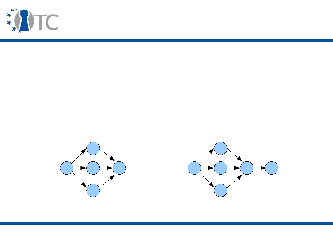
www.opentc.net
30 March 2007
27
Reputation/Recommendation Systems
(3)
• Another important aspect of Recommendation Systems
is the identification of users.
– Sybil attack can be very costly, depending on cost of
creating a new ID.
• Topological aspects can also complicate the
calculations: reputation is reinforced by several good
recommendations, but these can sometimes be
transferred from the same user.
A
B
Recommenders
reinforcing
reputation
trustee
trustor
A
Recommenders
propagating the
same recommendation
B

www.opentc.net
30 March 2007
28
Arguments against Trusted Computing (1)
• Some consumer movements have taken a more critical
view of Trusted Computing.
– Various stories in the USA (the Fritz chip, Microsoft's
antitrust lawsuit, Intel's Pentium 3's serial number
scandal) created a lot of suspicion towards significant
security initiatives.
– The similarity between the TCPA, Microsoft NGSCB, and
Intel and AMD's projects cast doubts about the industry's
intentions (TCPA members are both the creators and
probable first users of the technology).
– Conflicts of interests between the industry and the
consumers occur more and more often.
– There were privacy concerns, but a lot of them have been
addressed in the successive versions of the TPM
specification.

www.opentc.net
30 March 2007
29
Arguments against Trusted Computing (2)
• Two main movements have emerged:
– Anti-TCPA (Ross Anderson);
• Richard Stallman, an important figure in the “free software”
world, leading the Free Software Foundation (FSF) and the
decisions behind the widely used GPL (GNU General Public
Licence), has a similar point of view.
– EFF (Electronic Frontier Foundation).

www.opentc.net
30 March 2007
30
Arguments of anti-TCPA (1)
• A lot of the anti-TCPA arguments are based on pseudo-
fictional stories presenting possible abuses of Trusted
Computing, extrapolating existing stories like the Fritz
chip, the Microsoft antitrust lawsuit or the Entertainment
industry sueing pirates.
• These arguments tie together the technology with the
law (anticompetitive behaviour, copyright laws,
freedom), politics (policy decision and enforcement,
censorship) and economics (change in industry balance,
policy fairness).

www.opentc.net
30 March 2007
31
Arguments of anti-TCPA (2)
• Richard Stallman argues that Trusted Computing will be
used to make “malicious features” pervasive and called
the initiative “Treacherous Computing”.
• Similarly to software code, Stallman wants cryptographic
keys to be visible to the user.
• Some clauses in the new GPLv3 address specifically the
status of DRM applications, trying to prevent them from
locking in content to particular platforms.
– Linus Torvalds (leader of the Linux kernel) replied by saying
that these clauses were too strong and “ensnaring innocent
and beneficial uses of encryption and DRM technologies”.
– These questions are related to ethics (fairness is not a
technical problem), and there is almost a philosophical split
(free vs. open).

www.opentc.net
30 March 2007
32
Arguments of the EFF (1)
• The EFF thinks the Trusted Computing threat model is
unclear.
– Is the PC Owner the adversary? Or the Service/Good
Supplier always trusted?
– What happens in the case of conflict of interests?
• Trusted Computing puts into question reverse
engineering and Free/Open-Source Software (FOSS).
– There are good uses of reverse engineering, for example
for minority platforms or user groups (e.g. SAMBA,
assistive technology for people with disabilities).
– The cost of certification may prohibits FOSS from getting
into the Trusted Computing world.

www.opentc.net
30 March 2007
33
Arguments of the EFF (2)
• Trusted Computing could be a threat to industry
competition and interoperability.
– Software lock-in: high cost of switching to other solutions,
minority systems may be marginalised.
– TCG indicates that there should be no “
artificial barriers
to
interoperability” but it is difficult to understand.
– Ability to interoperate can be limited by the use of
attestations (segregation).
– Furthermore, platforms could become obsolete without the
ability to emulate (virtualise) them
transparently
.
• Legal arguments can complicate the matter.
– A legitimate business reason could be to “protect the
incentives to investment” or “protect the viability of new
business models”.

www.opentc.net
30 March 2007
34
Arguments of the EFF (3)
• The TCG notion of control is biased, leaving the PC
Owner only with the ability to turn on or off the TPM.
– Need for a more fine-grained notion of control.
• Security goals can become coercion.
– E.g. websites forcing the use of a particular browser.
• Priorities between the different stakeholders is unclear.
– Does the execution of software imply that the software
complies with the Owner's policy? (e.g. spyware)

www.opentc.net
30 March 2007
35
Arguments of the EFF (4)
• The EFF proposed several ideas to solve the problems
they mention:
–
Owner override
: the Owner can choose to disclose the
system configuration without the modifications that he
made;
–
Owner gets key
: the Owner can use the TPM's attestation
identity private key to generate signatures himself;
–
Owner generates key
: the Owner can create and import
attestation identity key pairs into the TPM;
– Policy transparency at all levels;
– Limit attestations to a group of platforms;
– Slow attestation.

www.opentc.net
30 March 2007
36
The Future of Trusted Computing (1)
• The TCG view of the evolution of Trusted Computing
(see first lecture):
1) TPM deployment;
2) Platform root-of-trust;
3) Operating System chain of trust;
4) Trusted Computing applications (Enterprise);
5) Trusted Ecosystem.

www.opentc.net
30 March 2007
37
The Future of Trusted Computing (2)
• The manufacturing of TPMs and Trusted Computing
applications in the enterprise environment is already
under way.
– Six main TPM manufacturers (Atmel, Broadcom, Infineon,
Winbond, ST Microelectronics, Sinosun).
– OEMs ship TPMs mostly in laptops for the moment.
• But the US Army for example requires their new computers to
have a TPM.
– TCG Software Stacks (TSS) are available (TrouSerS, NTRU,
Infineon).
– Linux is Trusted Computing-ready and Windows Vista's
Trusted Computing features only in the Ultimate and
Enterprise editions.
– Intel LT and AMD-V hardware platforms are being deployed.

www.opentc.net
30 March 2007
38
The Future of Trusted Computing (3)
• Example of the problems currently highlighted in the
TCG specifications:
– Binaries are currently being measured and attested to, but
it obliges the verifier either to maintain a big database of
binary hashes or limit the number of accepted states in
order to be able to determine the state trustworthiness;
– Furthermore there are also privacy issues (the platform is
revealing exact information about hardware and software);
– Property-based attestations have been proposed to
remedy this problem.

www.opentc.net
30 March 2007
39
The Future of Trusted Computing (4)
• Software (Operating System and application) will
determine how successful the Trusted Computing
paradigm is.
– Trusted virtualisation is seen as the next critical next step
(blue pill attack/VMM malware).
– A lot of security functionalities are available to developers:
which ones will prove successful?
– First applications deployed: strong authentication and
drive encryption (BitLocker).
• A big challenge in the long term: non-business
applications? For example e-Government or e-Business.
– Will there be “islands of trust”?

www.opentc.net
30 March 2007
40
The Future of Trusted Computing (5)
• The Trusted Computing infrastructure will be rolled out
(e.g. Privacy-CAs).
– First at a local (corporate) level.
– At a global level, scalability is paramount to ensure
efficient mechanisms.
• Certification of the TPM and the platform is an important
challenge that may require changes to the industrial
production processes.

www.opentc.net
30 March 2007
41
The Future of Trusted Computing (6)
• Meanwhile, new Trusted Computing specifications are
coming, and new platforms will benefit from Trusted
Computing (Mobile, PDA, Server).
– As mentioned before, there may be a TPM version 1.3.
• In the longer term, Trusted OSs will have to be
developed:
– Non-monolithic kernels and software verification;
– Full use of the Trusted Computing capabilities;
– Ability to make complex trust decisions (policy problem).
• Trusted Network Connect (TNC) may also play an
important role in completing the Trusted Computing
framework.

www.opentc.net
30 March 2007
42
The Future of Trusted Computing (7)
• Ultimately, a
trusted ecosystem
will comprise many
different entities interacting dynamically in a complex
and trustworthy manner.
• All the different facets of trust will have to be satisfied:
– Legal status;
– Socio-psychological acceptability;
– Economic cost;
– Security and privacy.

www.opentc.net
30 March 2007
43
References (1)
• Richard Walton. Cryptography and trust. Information
Security Technical Report, vol. 11, No. 2 , pages 68-71,
2006.
• D. H. McKnight, N.L. Chervany. The Meaning of Trust. In
Trust in Cyber-societies, Springer LNAI 2246, pages 27-
54, 2001.
• N. Luhmann. Trust as a Reduction of Complexity. In
Trust and Power: Two works by Nikals Luhmann. John
Wiley & Sons, 1979, pages 24-31.
• Stephen Weeks. Understanding trust management
systems. Proceedings of the IEEE Symposium on
Security and Privacy, pages 94--105, 2001.

www.opentc.net
30 March 2007
44
References (2)
• Anti-TCPA FAQ: http://www.cl.cam.ac.uk/~rja14/tcpa-
faq.html
• Seth Schoen. EFF Comments on TCG Design,
Implementation and Usage Principle 0.95. October 2004.
• Catherine Flick. The Controversy over Trusted
Computing. University of Sydney, June 2004.
• Klaus Kursawe. The future of trust computing: an
outlook. In Chris Mitchell ed., Trusted Computing, 2005,
IEE Press, pages 299-304.

www.opentc.net
30 March 2007
45
The information in this document is provided “as is”, and no guarantee or
warranty is given that the information is fit for any particular purpose.
The user thereof uses the information at its sole risk and liability.
The Open-TC project is co-financed by the EC.
If you need further information, please visit our website
www.opentc.net or contact the coordinator:
Technikon Forschungs- und Planungsgesellschaft mbH
Richard-Wagner-Strasse 7, 9500 Villach, AUSTRIA
Tel.
+
43 4242 23355 – 0
Fax.
+
43 4242 23355 – 77
Email coordination@opentc.net
Open_TC EC Contract No: IST-027635

MSc in Information Security - Trusted Computing
Eimear Gallery -
e.m.gallery@rhul.ac.uk
Coursework 1 - Total: 60 marks
Set date: 19
th
Feb 07 - Submission date: 5
th
Mar 07
Answers should be preferably handed in at the TC lecture on the 23
rd
Feb or the 2
nd
March. Alternatively, you may e-mail your answers.
1. Describe the components which comprise a TPM.
[11 marks]
2. A TPM has both activation and enablement controls. What is the purpose of
having both?
[4 marks]
3. Describe the TPM endorsement key pair.
[4 marks]
4. Describe, with the aid of a diagram, a simplified PC authenticated boot process.
[4 marks]
5. What is the difference between an authenticated boot process and a secure boot
process?
[3 marks]
6. What is the name of the key used during platform attestation? [1 mark]
7. What are the properties of this key?
[3 marks]
8. How is such a key created and certified.
[6 marks]
9. Describe the contents of an attestation identity key credential. [2 marks]
10. Describe the process of platform attestation to a challenger of the platform –
Include in your description an outline of the input and output parameters to the
TPM_Quote command (see
www.trustedcomputinggroup.org
for TPM command
specifications).
[5 marks]
11. Describe five problems associated with verifying reported integrity metrics.
[5 marks]
12. Show, with the aid of a diagram, the key types which may exist in a protected
storage key hierarchy.
[3 marks]
13. Using the TPM protected storage functionality describe 2 ways by which it can be
assured that a credit card number can only be accessed when the TPM’s host
platform is in a particular software state.
[6 marks]
14. Describe two benefits/uses of the 20-bytes of usage authorisation data which may
be associated with a TPM protected object.
[3 marks]

MSc in Information Security - Trusted Computing
Eimear Gallery -
e.m.gallery@rhul.ac.uk
Coursework 1 - Total: 60 marks
Set date: 19
th
Feb 07 - Submission date: 5
th
Mar 07
Solutions
1. Describe the components which comprise a TPM.
[11 marks]
I/O:
●
Manages flow of information over the communications bus.
●
It performs encoding/decoding suitable for internal and external buses.
●
It routes messages to the appropriate components within the TPM.
●
The I/O component enforces access control associated with TPM functions
requiring access control.
Cryptographic co-processor:
●
Asymmetric encryption/decryption
○
The TPM must support RSA;
○
The TPM must use RSA for encryption/decryption;
○
The TPM may implement other asymmetric algorithms for asymmetric
encryption/decryption, such as elliptic curve.
●
Symmetric encryption/decryption engine
○
Symmetric encryption is used by the TPM to:
■
Provide confidentiality of newly created authorisation data being sent
to the TPM;
■
Provide confidentiality during transport sessions;
■
Provide internal encryption of blobs stored off the TPM.
○
For authentication and transport sessions:
■
Stream cipher - XOR is used;
■
Key generation process is also specified in both cases.
○
For internal encryption of blobs stored off the TPM:
■
The TPM designer may choose any symmetric algorithm.
○
Symmetric encryption is not exposed for general message encryption.
●
Signature operations
○
The TPM must support the RSA algorithm for signature operations, where
signed data must be verified by entities other than the TPM which
performed the sign operation.
○
The TPM may use other algorithms for signature generation, e.g. DSA,
but there is no requirement that other TPM devices either accept or verify
those signatures.
Key generation:
●
The TPM must generate RSA key pairs.
○
The TPM must support key sizes of 512, 768, 1024 and 2048 bits (minimum
recommended = 2048 bits);

○
It is mandated that certain keys (the storage root key and attestation identity
keys, for example) must be at least 2048 bits.
●
The implementation must be in accordance with P1363- Standard specifications
for public-key cryptography.
HMAC engine:
●
The HMAC engine is also used in the authorisation mechanism:
○
Allows a TPM to verify that a caller knows the required authorisation data to
complete a particular action – for example, to utilise a particular command or
to access a particular key or piece of data.
○
It also enables the TPM to verify that no unauthorised modifications have
been made to an incoming command in transit.
RNG:
●
Comprised of three components:
○
Entropy source and collector;
○
State register; and
○
A mixing function.
●
Entropy source and collector
○
Entropy source: is the process or processes which provide entropy.
■
Sources include noise, clock variations, for example.
○
The collector: is the process that collects the entropy, removes the bias and
smooths the output.
■
For example, if the raw entropy data has a bias of 60% 1s and 40% 0s then
the collector takes this information into account before sending data to the
state register.
●
State register
○
Where the output from the entropy collector is stored.
○
The implementation may use 2 registers – a non-volatile and a volatile:
■
The state of non-volatile register is stored to the volatile register on start-
up.
■
Changes to the state of the state register from either the entropy source or
mixing function affect the volatile register.
■
The state of the volatile register is stored to the non-volatile register at
power down.
■
Avoids overuse of flash.
●
Mixing function
○
Takes the state register and produces the RNG output.
SHA-1 engine:
●
The TPM must implement the SHA-1 hash algorithm as defined in FIP-180-1.
●
The output of SHA-1 is 160 bits and all areas that expect a hash value must
support the full 160 bits.
●
Security issue – significant weaknesses have been discovered in SHA-1.

Opt-in component:
●
The opt-in component provides mechanisms to allow the TPM to be turned
on/off, enabled/disabled, activated/deactivated.
●
This component also maintains the state of persistent and non-volatile flags and
enforces the semantics associated with these flags.
Execution engine:
●
Runs the program code to execute TPM commands received from the I/O port.
Non-volatile memory:
●
Non-volatile memory is used to store persistent identity and state information
associated with the TPM.
○
Sample data stored – the endorsement key.
●
Must also support the functionality of a Data Integrity Register (DIR):
○
The TPM must provide one 20-byte non-volatile register called a DIR.
Power detection:
●
The power detection component manages the TPM power states in conjunction
with platform power states. TCG requires that the TPM be notified of all power
state changes.
●
Power detection also supports physical presence assertions. The TPM may restrict
command-execution during periods when the operation of the platform is
physically constrained.
Volatile memory:
e.g. PCRs:
●
A PCR is a 160-bit/20-byte storage location which is used to store integrity
measurements.
●
A TPM must support a minimum of 16 PCRs.
●
Whether a PCR must be used to store a specific measurement (e.g. the CRTM,
BIOS…Option ROM code…), or, whether it is available for general use, is
specified in platform specific specifications.
2. A TPM has both activation and enablement controls. What is the purpose of
having both?
[4 marks]
Sample attack scenario:
●
If there was no activation/deactivation functionality:
●
If the TPM:
○
is enabled; AND
○
fFlags.OwnershipEnabled = true.
●
Rogue software could then take ownership of TPM and have the full range of
TPM functionality available to it.
●
However, when the TPM:
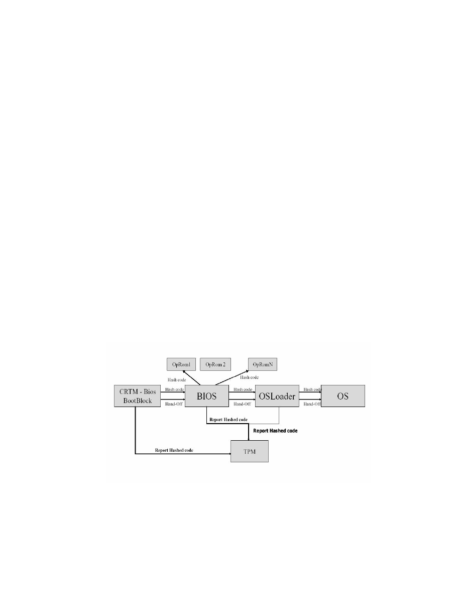
○
is enabled;
○
fFlags.OwnershipEnabled = true; AND
○
permanently deactivated;
●
The genuine TPM owner can execute the take ownership process, and then turn
on the remaining TPM functions by physically activating the TPM.
●
If a remote entity (software) successfully executes the take ownership command
on a deactivated TP before the legitimate owner, it will gain only restricted access
to TP functionality until the platform is activated.
●
As physical presence is required for TPM activation, the remote software cannot
perform this step, and thus the potential control that rogue software may have
over a hijacked TPM is limited.
3. Describe the TPM endorsement key pair.
[4 marks]
●
An 2048-bit RSA asymmetric key pair located in a TPM’s non-volatile memory.
●
A TPM has one such endorsement key pair.
●
The private key from this key pair is used for decryption; never for signature
operations.
○
It is never exposed outside of the TPM.
●
The public key from this pair may be exported outside the TPM to be used by
external entities.
○
Used to assert ownership over a TPM;
○
Also used to deliver pseudonymous identities/attestation identities to a TPM.
4. Describe, with the aid of a diagram, a simplified PC authenticated boot
process.
[4 marks]
Figure 1: The Authenticated boot process
The authenticated boot process is shown in figure 1.

In a PC, where the CRTM may be integrated into part of the BIOS called the BIOS boot
block (BBB), integrity metrics may be measured and recorded as follows:
●
The BBB (the CRTM) starts the boot process, measures its own integrity and the
integrity of the entire BIOS, and stores the details of the measured components in
the stored measurement log (SML), saving the integrity measurements (hash
values of the components measured) in a TPM platform configuration register
(PCR);
●
The BBB then passes control to the BIOS, which contains a measurement agent
(MA) responsible for measuring the option ROMs, storing the details of the
measured components in the SML and the integrity measurements in a TPM PCR;
●
Control is then passed from the BIOS to the option ROMs, which carry out their
normal operations and pass control back to the BIOS;
●
The BIOS then measures the OS loader, and stores the details of the measured
component in the SML and the integrity measurement in a TPM PCR;
●
Control is then passed to the OS loader, also containing an integrated MA, which
carries out its normal functions and then measures the OS, stores the details of the
measured component in the SML and the integrity measurement in a TPM PCR;
●
Finally, control is passed to the OS.
5. What is the difference between an authenticated boot process and a secure
boot process?
[3 marks]
●
Authenticated boot process: The process by which measurements about the
firmware/software state of the platform (integrity measurements) are reliably
measured
and
stored
(but not checked/validated).
●
Secure boot process: The process by which measurements about the
firmware/software state of the platform (integrity measurements) are reliably
measured, checked/validated against the expected values
and then
stored
.
6. What is the name of the key used during platform attestation? [1 mark]
●
Attestation identity key
7. What are the properties of this key?
[3 marks]
●
An AIK is a RSA 2048-bit key pair.
●
The private key from an AIK pair can be used to digitally sign data generated by
the TPM:
○
PCR information;
○
Non-migratable keys generated by the TPM.
●
The public key from this AIK pair is used to verify digital signatures generated by
the TPM.
●
A TPM may have an unlimited number of AIKs.
8. How is such a key created and certified.
[6 marks]

The procedure used to allow a TPM owner to create a TPM identity and obtain an AIK
credential has two main steps: identity creation and identity activation.
1. The platform sends a message to the TPM requesting the generation of an AIK
pair. The properties of the key pair to be generated are specified as input. The
digest of the ‘identity label’ chosen by the TPM owner and an identifier for the P-
CA chosen to certify the new identity, are also input.
2. The AIK key pair is then generated by the TPM.
3. The TPM creates an identity-binding:
●
The TPM takes:
○
The public key from the newly generated AIK; and
○
The digest of the ‘identity label’ chosen by the TPM owner and an
identifier for the P-CA chosen to certify the new identity.
●
Generates a digital signature (using the private AIK) over the above data.
4. A TSS command is called to assemble all data needed by the P-CA, i.e. the
platform credential set, all data linked to the identity-binding (i.e. the public key
from the newly generated AIK pair, the ‘identity label’, and the identifier for the
P-CA), and the identity-binding.
5. The assembled data is then sent to the chosen P-CA, encrypted under the public
key of that P-CA.
6. The P-CA decrypts the bundle received.
7. The P-CA inspects the credentials and checks whether it is indeed the P-CA being
asked to generate the new identity for the TP.
8. The P-CA then creates an AIK credential, encrypts it with a symmetric key, and
encrypts the symmetric key such that it can only be decrypted by that specific
TPM, verified as genuine (using the public endorsement key of the TPM).
9. A hash of the AIK public key is also generated by the P-CA and encrypted using
the public endorsement key of the TPM.
10. These items are then sent to the TPM.
11. The TPM decrypts the hash of the AIK public key and the symmetric key used to
encrypt the AIK credential.
12. The TPM then compares the decrypted hash of the AIK public key received
against the hashes of all its public AIKs (if the data was intended for this TPM,
then the hash will equal the hash of a public AIK belonging to the TPM).
13. If a match is found, the TPM releases the decrypted P-CA symmetric key to the
host platform.
14. Release of the symmetric key permits the decryption of the AIK credential.
9. Describe the contents of an attestation identity key credential. [2 marks]
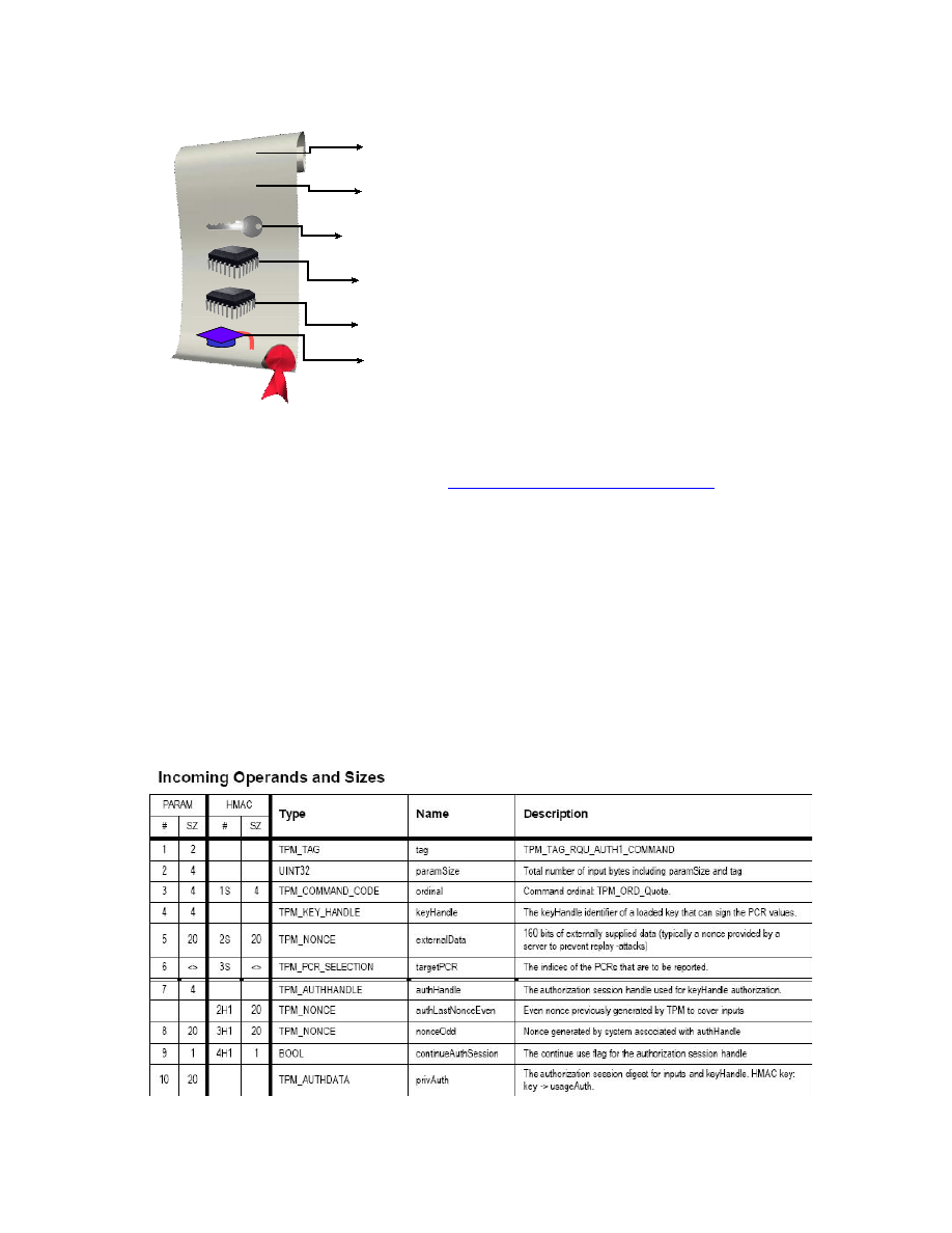
10.
Describe the process of platform attestation to a challenger of the platform –
Include in your description an outline of the input and output parameters to
the TPM_Quote command (see
www.trustedcomputinggroup.org
for TPM
command specifications).
[5 marks]
●
A challenger presents the TP with an integrity challenge or nonce and the indices
of the platform configuration registers that are to be reported.
●
The TPM signs the nonce and the relevant PCR values, using a private AIK.
●
This signed data is then forwarded to the challenger, in conjunction with the
relevant SML entries and TP AIK credential
.
●
The challenger validates the response using the appropriate validation certificates,
and makes a decision whether the challenged TP can be trusted for the intended
purpose.
TPM_Quote:
Platform attestation identity
credential
S tring
"TC P A TP M Identity"
TP M identity chos en name
P latform type + platform s ecurity properties
P rivacy-C A reference
S tring
TP M type + TP M s ecurity properties
TP M attes tation identity public key
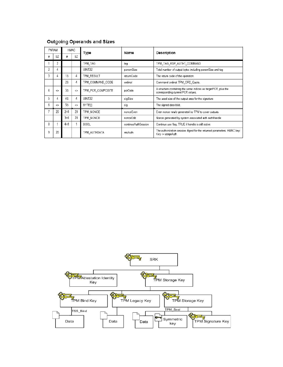
11. Describe five problems associated with verifying reported integrity metrics.
[5 marks]
1. Open source software problems.
2. It says nothing about the behaviour of the platform.
3. It is static, inflexible, perhaps inexpressive - it can convey no dynamic
information about a program such as runtime state or the properties of the input it
is acting upon
.
4. Upgrades and patches are difficult to deal with - exponential blow-up in the space
of possible binaries for a program.
5. In compatible with a widely varying, heterogeneous computing platform.
6. Problems with revocation.
12. Show, with the aid of a diagram, the key types which may exist in a protected
storage key hierarchy.
[3 marks]

●
Storage keys
○
Used by TCG-aware applications;
○
Used to encrypt other keys and arbitrary data;
○
Storage keys must be as strong as 2048-bit RSA;
○
Keys may be migratable or non-migratable.
●
Signature keys
○
Used by TCG-aware applications;
○
Used to sign arbitrary data;
○
Keys may be migratable or non-migratable.
●
Attestation identity keys
○
Non-migratable signing keys;
○
Exclusively used to sign data originated from the TPM (PCR data, non-
migratable TPM keys).
●
Bind keys
○
Used to encrypt data on one platform for decryption on another (within the
TPM).
●
Legacy keys
○
Created outside the TPM.
○
They can be imported to the TPM after which they may be used for signing
and encryption operations.
13. Using the TPM protected storage functionality describe 2 ways by which it
can be assured that a credit card number can only be accessed when the
TPM’s host platform is in a particular software state.
[6 marks]
TPM_CreateWrapKey – Create an asymmetric key pair where private key use is not
bound to PCRs.
TPM_Seal – Seal the credit card number to a set of PCR values.
TPM_CreateWrapKey – Create an asymmetric key pair where private key use is bound to
PCRs.
Encrypt the credit card number with the corresponding public key.
14. Describe two benefits/uses of the 20-bytes of usage authorisation data which
may be associated with a TPM protected object.
[3 marks]
1. The integrity of keys/data can be protected - 20 bytes of authorisation data which
may be associated with a key/data;
2. Unauthorised access to data/used of keys can be prevented – PCR data and 20
bytes of authorisation data.

MSc in Information Security – Trusted Computing (IY5608)
St´
ephane Lo Presti – Stephane.Lo-Presti@rhul.ac.uk
Coursework 2 – Total: 45 marks
Set date: 27 March 07 – Submission date: 16 April 07
Solutions
1. What is a Dynamic Root of Trust for Measurement (DRTM)? Explain
how it is implemented on either the Intel LaGrande Technology (LT) or
the AMD-V architecture.
[3 marks]
A Dynamic Root of Trust for Measurement (DRTM) is a Root of Trust
for Measurement (RTM) that can be started at an arbitrary point in time,
as opposed to the Core RTM (CRTM) (or Static RTM, SRTM) which is
started at platform boot time only. The integrity of the process of starting
a DRTM cannot be compromised by the software executing before the
DRTM invocation point, so that the DRTM enables a designated software
component (e.g. a Virtual Machine Monitor/VMM) to be started into a
trustworthy state at any point in time.
In an AMD-V hardware platform, the DRTM is implemented as the
SKINIT instruction which starts a Secure Kernel (SK) code in an atomic
manner and into a trustworthy state. In the Intel LT platform, the DRTM
is implemented as the GETSEC[SENTER] instruction which similarly
starts a Measured Virtual Machine Monitor (MVMM).
2. Define what a Virtual Machine Monitor (VMM) is, explain what its main
function is and give two examples of how to improve its security using the
Intel LaGrande Technology (LT).
[6 marks]
A Virtual Machine Monitor (VMM) (or hypervisor), also called Domain
Manager in LT, is a piece of software that creates and manages Virtual
Machines (VMs). A VM is typically composed of an Operating System
(OS) and its applications. The VMM provides to the VMs transparent
access to the platform hardware and executes the VMs in parallel and
isolated from each other. The VMM manages the memory, resources and
communication channels, and makes the platform policy decisions and
enforces them.
LT improves the security of a VMM via the following features:
•
a secure launch via a DRTM (see previous question) that ensures
that the VMM is measured, its measurement is stored securely in the
TPM in one of the dynamic PCRs (Platform Configuration Registers,
number 17 to 22), and it is started in a well-known trustworthy state;
•
a privileged execution mode (or ”ring”) so that the VMM can run
with higher privileges than the VMs it manages and keep control of
the execution, notably enforce policy decisions;
•
its own hardware-protected memory space separated from other soft-
ware;
1

•
two VMX modes of operation that are used respectively when a VMM
or a VM are executing; this ensures that attempts by a VM to execute
a privileged operations is trapped and redirected to the VMM which
decides whether or not to execute it, and makes the necessary actions
in the latter case;
•
a secure management of the DMA (Direct Memory Access) feature
via the NoDMA table used to deny DMA access to unauthorised
VMs;
•
co-management of the interrupts sent to the VMs, the MVMM and
other hardware components in conjunction with the STM (SMI Trans-
fer Module) component;
•
a VM Control Structure (VMCS) to store execution information
about the VMM and its VMs.
3. Two Trusted Computing applications need to communicate through the
network. Describe two ways to do that using the TCG Software Stack
(TSS).
[4 marks]
There are two straightforward way to use the TSS to make the two Trusted
Computing applications communicate through the network:
•
The remote application (origin of the communication) uses the TSP
(TSS Service Provider) layer of the TSS to access the TCS (TSS Core
Services) layer of the TSS used by the local application (the one being
contacted); a specific Remote Procedure Call (RPC) mechanism is
used during this communication that is specified by the TCG as Web
Services over SOAP (Simple Object Access Protocol), but TSS ven-
dors can also provide a proprietary communication mechanism; the
TCS policy can be used to allow or disallow remote communications
depending on the party trying to communicate;
•
The two applications can use TSP contexts to connect directly two
executing threads within these applications.
4. Define the four execution modes of the AEGIS processor and how they
are used to protect processes and data.
[6 marks]
The four AEGIS processor execution modes are:
•
Standard (STD);
•
Suspended Secure Processing (SSP);
•
Tamper-evident (TE);
•
Private Tamper-resistant (PTR).
The STP and SSP modes are used for unprotected processes and data,
so they do not provide any security and is used for legacy code. STD
and SSP mode differ by the possibility to use virtual memory in the first
2

one but not the second, and to transition from the secure modes (TE and
PTR) to the SSP, but not to the STD.
The TE mode enables the guaranteed detection of physical and software
tampering. In this mode, programs can access parts of memory designated
as Integrity Verification (IV). This mode is started by the l.secure.enter
instruction. A hash of the program code is then obtained and stored in
protected storage, and the execution environment’s sanity is then checked.
The program is protected from interrupts by preserving the registers over
interrupts.
The PTR mode ensures, in addition to the detection of tampering, that an
adversary cannot gain any information by tampering with or observing the
system operations. In this mode, programs can access parts of memory
designated as Integrity Verification (IV) and Memory Encrypted (ME),
where data is encrypted using a One-Time Pad (OTP). The PTR mode is
launched via the l.secure.csm instruction. A static key and the program
hash are then encrypted under the public key of the AEGIS processor (with
a hash of the security kernel if it is available). Register access rights are
enforced so that only processes with the corresponding access rights can
use them. The virtual address is used to determine if information exported
to off-chip memory has to be protected, following a convention on the
second Most Significant Bit (MSB). The register values are securely saved
when an interrupt occurs and they are then cleared, and then restored after
the interrupt handler finishes. Furthermore, the PTR mode enables access
to the secret generation functions (Physical Unclonable Function/PUF).
The AEGIS processor ensures that transition between the modes follow
a strictly enforced order so that execution protection cannot be circum-
vented., see Figure 1 below.
(Figure 1)
STD <-------------------> TE <------------> PTR <-----------------------> SSP
l.secure.enter/exit
^
l.secure.csm
l.secure.suspend/resume
^
|
|
--------------------------------------------------
l.secure.suspend/resume
5. Describe the execution of the
GETSEC[SENTER]
instruction in the Intel
LaGrande Technology (LT) architecture. In your description, you must
detail the various elements (code, tables, etc.) of LT initialised or used by
this instruction.
[10 marks]
The
GETSEC[SENTER]
instruction, executed in the SMX instruction mode,
is invoked to securely launch a VMM (making it a Measured VMM,
MVMM). The launching process (BIOS, OS loader or OS) must be in
ring 0 and the processor from which it was launched (Initiating Logical
3

Processor) must take control of the platform to ensure that this instruc-
tion is atomic. This is done by putting to sleep the other processors and
suspending interrupts at the beginning of the execution of the instruction.
Access to the TPM are done via PC-Specific commands only available
from locality 4 and memory-mapped.
A signed Authenticated Code (AC) denoted SINIT is loaded in memory by
the launching process, together with the code designated to be launched
(VMM) in a trustworthy state by the
GETSEC
instruction. All events are
disabled until the instruction is completed. SINIT is then measured, the
measurement is stored in the TPM and SINIT is executed from locality 3
(corresponding to auxiliary components) in a specific memory space if the
signature is validated. SINIT tests the hardware configuration, validates
and launches the STM (Secure Message Interrupt/SMI transfer Monitor)
in order to negotiate an interrupt policy, enables the NoDMA functionality,
measures the SCLEAN AC (which is in charge of clearing secrets and keys
in case of a component failure) into PCR[17], then measures the VMM,
performs basic checks on its page table and, if successful, adds the MVMM
pages to the NoDMA table and measures them. It finally stores the VMM
measurement in PCR[18], and finally launches the VMM (in the privileged
mode of execution). The MVMM then re-enable the interrupts and SMI
events, and wake up the processors that were put to sleep.
During the secure launch process, any problem triggers an
LT-shutdown
error that ensures that sensitive information in the various hardware com-
ponents are masked and the platform is reset with an indication of the
error type stored in a processor register.
The MVMM shuts itself down by invoking the
GETSEC[SEXIT]
instruction
that functions as
GETSEC[SENTER]
and makes sure that the environment
is put back in a consistent state where no VMM executes.
6. Give five examples of how Trusted Computing technologies can be used
to improve the security of Grid or Peer-to-Peer applications.
[5 marks]
Grid:
•
Protection of the privacy, confidentiality and integrity protection of
the user’s computation data;
•
protection of the resource provider platform’s security form the guest
user;
•
enforcement of the Virtual Organisation (VO) policy via VO software
integrity;
•
remove the need for long certificate chain thanks to key management
and migration features;
•
credential and key protection inside the TPM and via sealing to the
VO software;
•
Virtualisation to protect from OS and application threats.
4

Peer-to-Peer:
•
Anonymous identities (pseudonyms) strongly authenticated via the
DAA protocol;
•
Access control implemented by the DAA Issuer when issuing DAA
credentials;
•
Peer-to-Peer software integrity in order to enforce fair usage policies;
•
Software attestation used to built reliable connections between mutually-
trusted nodes.
7. Describe the authenticated boot process of Windows Vista in the case of
a BIOS firmware.
[4 marks]
The detailed boot sequence in the case of a BIOS firmware is the following
(see figure 2):
(figure 2)
3
4
5
6
BIOS
---------------> MBR -------------> IPL -----> BOOTMGR ---> OS loader
(configuration
(partition
data)
table)
|
^
1|
|2
V
|
Option ROM
(configuration
data)
During this boot sequence, Windows Vista’s authenticated boot process
proceeds as follows:
•
PCR[0] to PCR[15] are reset;
•
The CRTM measures the BIOS and its associated data (hardware
configuration), stores the measurements in PCR[0] and PCR[1], and
starts the BIOS;
•
The BIOS measures the option ROMs and its configuration data, and
stores the measurements into PCR[2] and PCR[3];
•
Similarly, measurements of the Master Boot Record (MBR) code
portion and the partition table are stored respectively into PCR[4]
and PCR[5];
•
The Master Boot Record (MBR) then starts by determining the
active boot partition, loads the first sector of the boot partition,
measures the first 512 bytes of that sector (called Initial Program
Loader/IPL) and stores the measurement into PCR[8]. The boot
sector loads and measures the remaining boot code, and stores the
measurement into PCR[9];
5

•
The boot code searches and loads the BOOTMGR boot manager,
measures it and stores the measurement into PCR[10];
•
Several auxiliary pieces of information can be measured and their
measurements stored into PCR[11], for example the current boot
status, some Operating System secrets and the BitLocker encryption
key;
•
The boot manager BOOTMGR transfers control to the OS loader
for the specified partition. The OS loader ensures the integrity of
all Windows components before transferring control to the operating
system. The operating system then ensures the integrity of system
files (hibernation, swap, crash) and all executables loaded up to,
including, and after an authenticated logon (at this point, BitLocker
Drive Encryption/BDE is executed, if it has been activated).
8. Explain the trusted sprite model of the Intel LaGrande Technology (LT)
architecture and how it is implemented.
[4 marks]
In the context of protected I/O, LT proposes the Trusted Sprite Model for
a trusted graphics engine illustrated in figure 3 (see below). The Trusted
Sprite Model builds a Trusted Surface that overlays the entire main display
surface and is stored in a specific secure memory space. The Trusted
Surface can only be accessed through the MVMM or a secure display
driver designated by the MVMM. Any other surface than the Trusted
Surface is only visible if the corresponding portion of the Trusted Surface
is set transparent; this is equivalent to say that the Trusted Surface has
the highest Z-order, where Z indicates the stacking order of surfaces on
the screen. The Trusted Sprite Model limits the graphics configuration
and ensures that the Trusted Surface is reconstructed after any graphics
configuration change.
In addition to these features, The Trusted Sprite Model provides a non-
spoofable panic mode screen (BSOD, Blue Screen Of Death) so that a
malicious software cannot use a system crash to access sensitive informa-
tion.
The Trusted Graphics Engine is organised as illustrated in figure 3 above.
Only trusted programs can access the Trusted Surface, under the supervi-
sion of the MVMM, which is then multiplexed with the untrusted graphics
memory information.
6

(figure 3)
DISPLAY
^
|
/-UNTRUSTED------------------|---------------TRUSTED------\
|
|
|
|
Multiplexer
|
|
^
|
^
|
|
|
|
|
|
|
Locked
|
|
|
assets
|
|
|
GTT (Graphics
^
|
|
TGTT (Trusted |
|
Translation
|
|
|
GTT)
|
\----Table)--------------|-- |-----|------------|---------/
|
|
|
|
address|
|
data
|
|address
/-------V-------------------------|------------|----------\
| Memory
V
|
|
TRUSTED SURFACE|
\---------------------------------------------------------/
9. List the four components on which Microsoft NGSCB is built, and two of
the hardware requirements of the NGSCB architecture.
[3 marks]
NGSCB components:
•
A Cryptographic chip called the Security Support Component (SSC),
or Security CoProcessor (SCP), that can securely store and access
cryptographic keys, and provides some protected storage (registers);
in practice, it is a TPM version 1.2;
•
A lightweight isolation kernel (or Security Kernel) used to isolate the
various guests and control access to the various hardware devices;
•
A mass market OS and untrusted applications (also called left-hand
side); the mass market OS is a legacy system (e.g. the Windows OS)
providing a wide range of functionality to the user and should run
in NGSCB almost unaffected from the point of view of performance
and functionalities;
•
High assurance components (also calked right-hand side) are small
components with limited and well-defined functionality, so that the
user can have confidence that these components behave correctly;
Microsoft proposes a small secure kernel called the Nexus.
NGSCB hardware requirements:
•
Input/Output (I/O) paths that can be created so that information
is communicated only between the program and the user using the
7

device, ensuring the integrity and confidentiality of the communica-
tion;
•
An access control to Direct Memory Access (DMA) devices, so that
the isolation layer can arbitrate access to the devices between the
guests;
•
A privileged CPU execution level (also called ”ring -1”) to run the
isolation layer under unmodified OSs (which expect to be executed
in ring 0, currently the most privileged level of execution).
8

MSc in Information Security – Trusted Computing (IY5608)
St´
ephane Lo Presti – Stephane.Lo-Presti@rhul.ac.uk
Coursework 2 – Total: 45 marks
Set date: 27 March 07 – Submission date: 16 April 07
Answers should be sent by e-mail, preferably as a text document.
You can also send pictures accompanying your text, in that case use
appropriate file names. PDF or Word is also acceptable.
1. What is a Dynamic Root of Trust for Measurement (DRTM)? Explain
how it is implemented on either the Intel LaGrande Technology (LT) or
the AMD-V architecture.
[3 marks]
2. Define what a Virtual Machine Monitor (VMM) is, explain what its main
function is and give two examples of how to improve its security using the
Intel LaGrande Technology (LT).
[6 marks]
3. Two Trusted Computing applications need to communicate through the
network. Describe two ways to do that using the TCG Software Stack
(TSS).
[4 marks]
4. Define the four execution modes of the AEGIS processor and how they
are used to protect processes and data.
[6 marks]
5. Describe the execution of the
GETSEC[SENTER]
instruction in the Intel
LaGrande Technology (LT) architecture. In your description, you must
detail the various elements (code, tables, etc.) of LT initialised or used by
this instruction.
[10 marks]
6. Give five examples of how Trusted Computing technologies can be used
to improve the security of Grid or Peer-to-Peer applications.
[5 marks]
7. Describe the authenticated boot process of Windows Vista in the case of
a BIOS firmware.
[4 marks]
8. Explain the trusted sprite model of the Intel LaGrande Technology (LT)
architecture and how it is implemented.
[4 marks]
9. List the four components on which Microsoft NGSCB is built, and two of
the hardware requirements of the NGSCB architecture.
[3 marks]
1
Trusted Computing Labs, IAIK TU Graz
1
Trusted Computing
TPM - Trusted
Platform Module
Thomas Winkler <
thomas.winkler@iaik.tugraz.at
>
v20070319

Trusted Computing Labs, IAIK TU Graz
2
Overview
●
Motivation
●
TC and TPM Design Goals
●
TPM Overview and TPM Specification
●
TPM Internals
●
Taking and Clearing TPM Ownership
●
TPM Keys, Key Creation and Key Hierarchy
●
Roots of Trust (RTM, RTR, RTS)
●
Attestation
●
Low-level TPM Interaction
●
Advanced TPM Concepts
Trusted Computing Labs, IAIK TU Graz
3
Motivation
●
several million of PCs, laptops, ... shipped with a TPM
●
many misconceptions and misunderstandings
●
What have you heard about TPMs?
–
Do you have a machine with a TPM?
–
Are you using it?
–
What do you think it
does?
–
What do you think
it can be used for?

Trusted Computing Labs, IAIK TU Graz
4
TC and TPM Design Goals
●
A trusted system is one that behaves in the expected manner for a
particular purpose (TCG).
–
How can that be achieved? Whom can you trust? The OS?
–
Would you trust your OS to be unmodified? If so - why?
–
If you don't know for sure that your OS really is in the state it
claims to be - why trust any software running on top of it?
●
How can one report the system state to a third party?
●
Assumption: Much easier to manipulate software than hardware.
–
Idea of TC: implement trust anchor in hardware -> TPM
●
TPMs are designed to be relatively low cost devices
–
important for market acceptance
–
limited resistance against sophisticated hardware attacks
–
not perfect security but better than pure software solution

Trusted Computing Labs, IAIK TU Graz
5
Fundamental TC Functionality
●
a mechanism to record (measure) what software is/was running
–
requires to monitor the boot process
–
needs an anchor to start the measurement from: a Root of Trust
–
nobody should be able to modify or forge these measurements
–
some shielded location for the measurements is required
●
now you know that your platform is in a defined state
–
Why should someone else believe this claim?
–
A mechanism to securely report the measurements to a 3rd party is
required.
–
The process of securely reporting the platform state is called
attestation.
●
secure storage
–
allow access to data only if system is in a known state

Trusted Computing Labs, IAIK TU Graz
6
TPM Overview
●
ancestors of todays TPMs showed up in IBM ThinkPads (called
Embedded Security Chip/Embedded Security Solution 1.0)
●
TPMs have resemblance with SmartCard technologies
●
standardization by TCG (formerly TCPA, see previous lecture)
●
open industry standard
●
specs freely available from www.trustedcomputinggroup.org
●
TPM specification versions 1.1b and 1.2
●
TCG keeps working on new / improved versions
●
TPM is a major building block to achieve the goals of a TC system

Trusted Computing Labs, IAIK TU Graz
7
TPM Overview
●
TPM spec is not targeted towards a specific device
●
other specs such as the PC Client or Mobile Phone Spec
"customize" the TPM spec for a specific device
●
TPM Manufacturers (in no particular order)
–
Infineon
–
ST Microelectronics
–
Atmel
–
Winbond (bought business unit from National Semiconductors)
–
Broadcom
–
SinoSun (China)
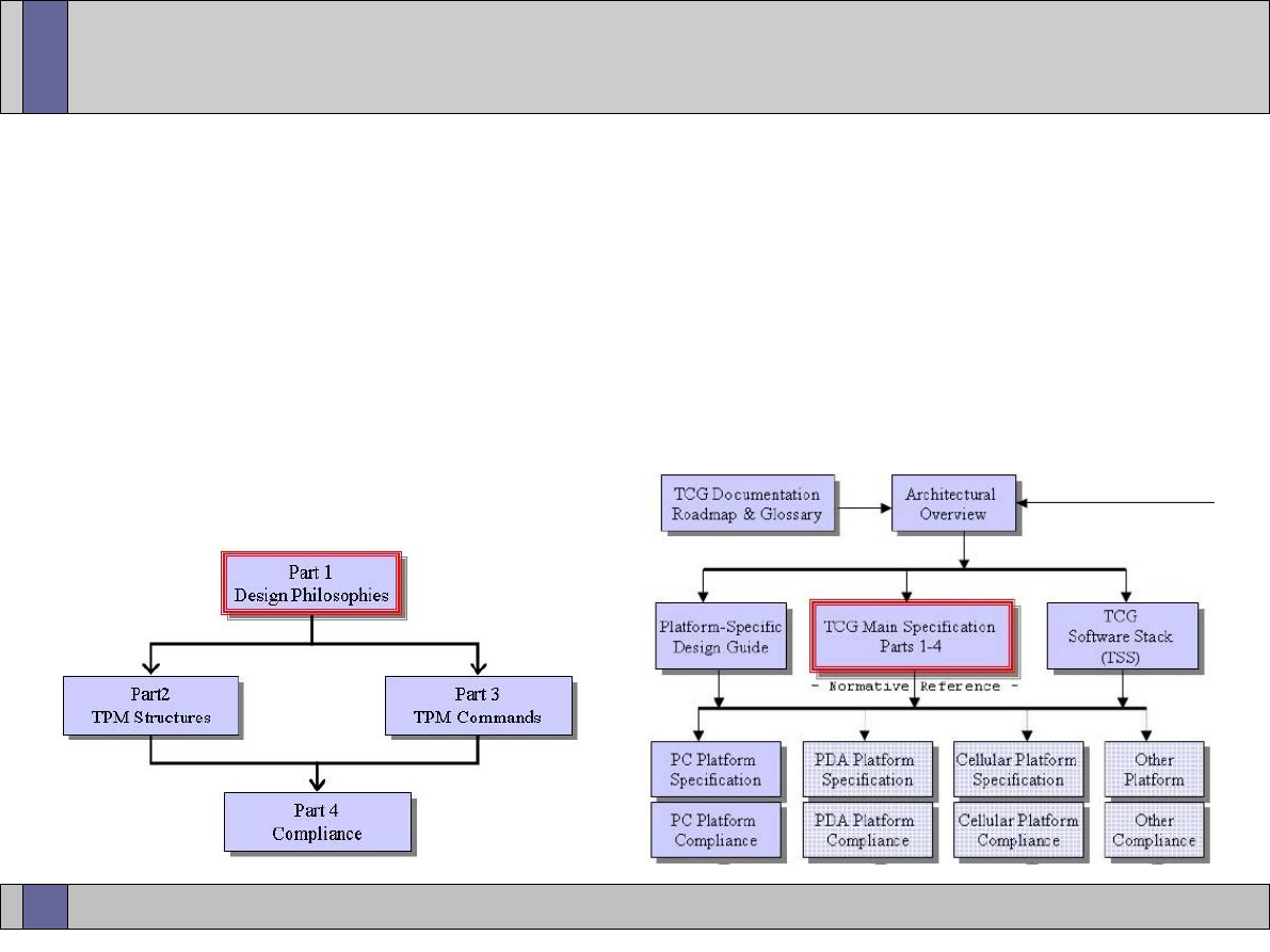
Trusted Computing Labs, IAIK TU Graz
8
TPM Specification
●
TCG TPM spec for 1.2 consists of 4 parts (600 to 700 pages total)
–
Part 1: Design Principles
Part 2: Structures and Constants
Part 3: Commands
Part 4: Compliance
–
all structures and commands are specified in C like syntax
–
additional platform specific spec (e.g. PC)
–
spec says nothing about internal TPM design or speed requirements
images © by TCG (TPM specification)

Trusted Computing Labs, IAIK TU Graz
9
TPM Internals
●
shielded location: an area where data is protected against
interference from the outside and exposure
●
protected capability: a function whose correct operation is
necessary in order for the operation of the TCG subsystem to be
trusted
●
only protected capabilities operate on data in shielded locations
●
both, shielded locations and protected capabilities are
implemented in hardware and therefore resistant against software
attacks
●
TPM is a slave device that does not actively initiate communication
●
TPM has no access to any system resources (LPC bus limitation)
●
consequence: TPM can not alter execution flow of system (e.g.
booting, execution of applications, ...)
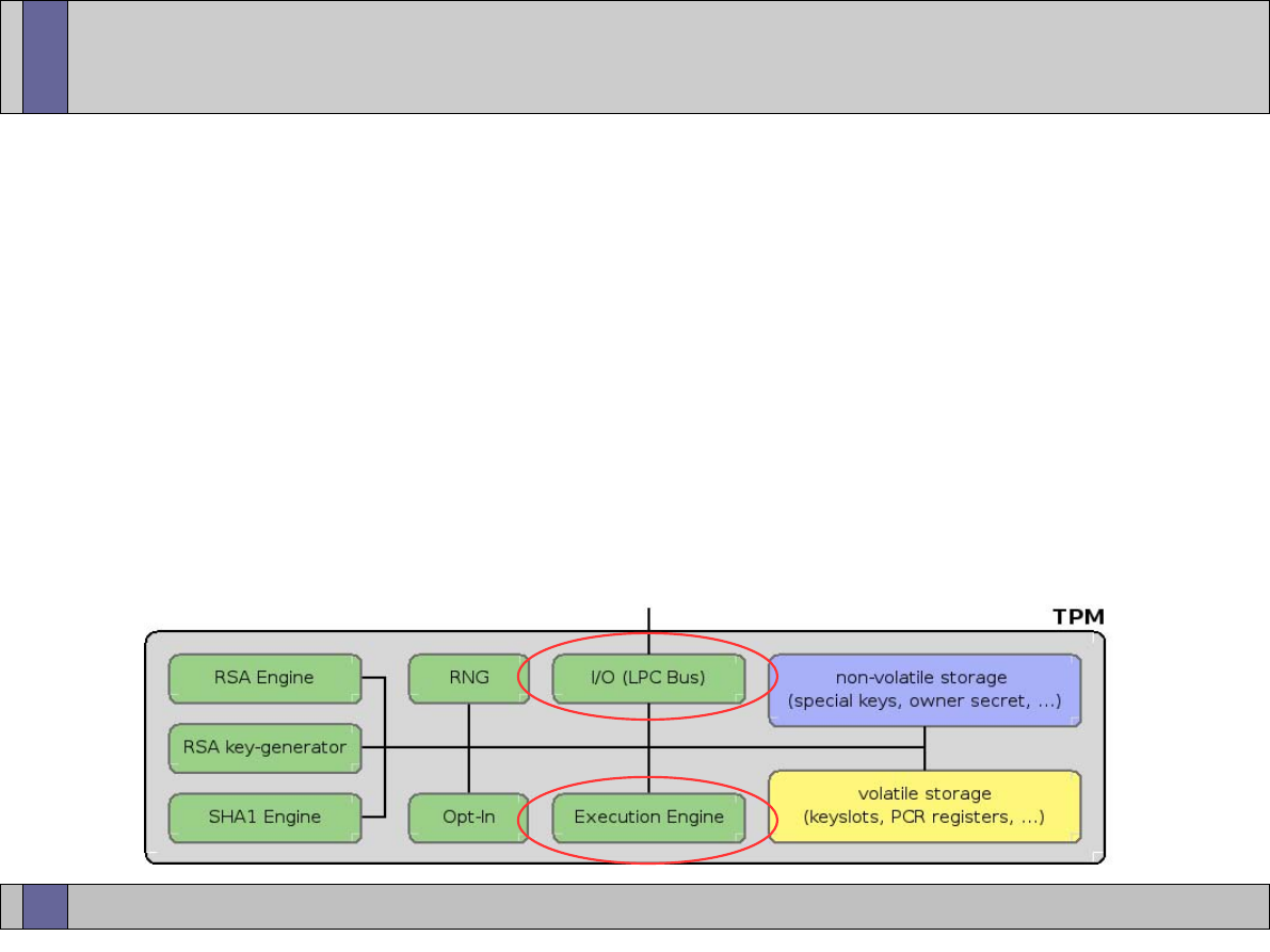
Trusted Computing Labs, IAIK TU Graz
10
TPM Internals
●
I/O
–
manages information flow over the communications bus
–
typically LPC - Low PinCount Bus, SM-Bus
●
Execution Engine
–
command verification and parsing
–
execution of the appropriate command code
–
controls internal TPM execution flow
–
micro-controller
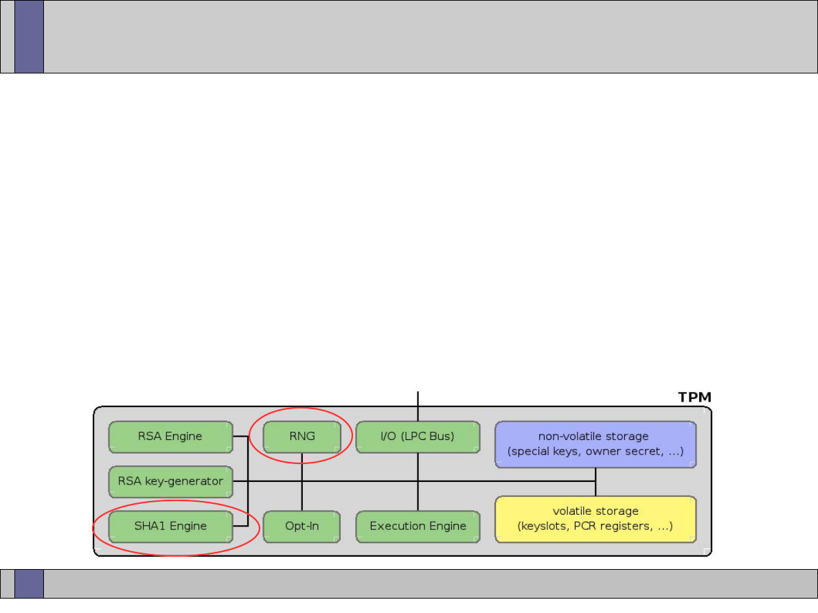
Trusted Computing Labs, IAIK TU Graz
11
TPM Internals
●
SHA-1 Engine (160 bits)
–
primarily used by the TPM as its trusted hash algorithm
–
exposed to the outside to be used in the boot process
–
TPM is not a crypto accelerator
–
future TPM revisions likely to add additional hash functions
●
RNG
–
source of randomness in the TPM
–
used for nonces (Number Used Once), key generation, ...
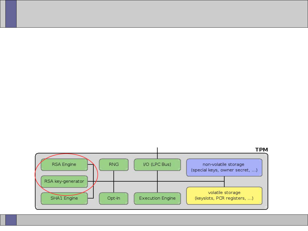
Trusted Computing Labs, IAIK TU Graz
12
TPM Internals - RSA
●
RSA Engine and Key Generator
–
asymmetric key generation (RSA; storage and AIK key size >= 2048)
–
must support 512, 1024, 2048 bit keys
–
use of 2048 recommended
–
RSA public exponent is fixed to 2^16 + 1
–
asymmetric encryption/decryption (RSA)
–
optionally may implement DSA, ECC (but no known implementation)
–
to use an RSA key it has to be loaded into the TPM
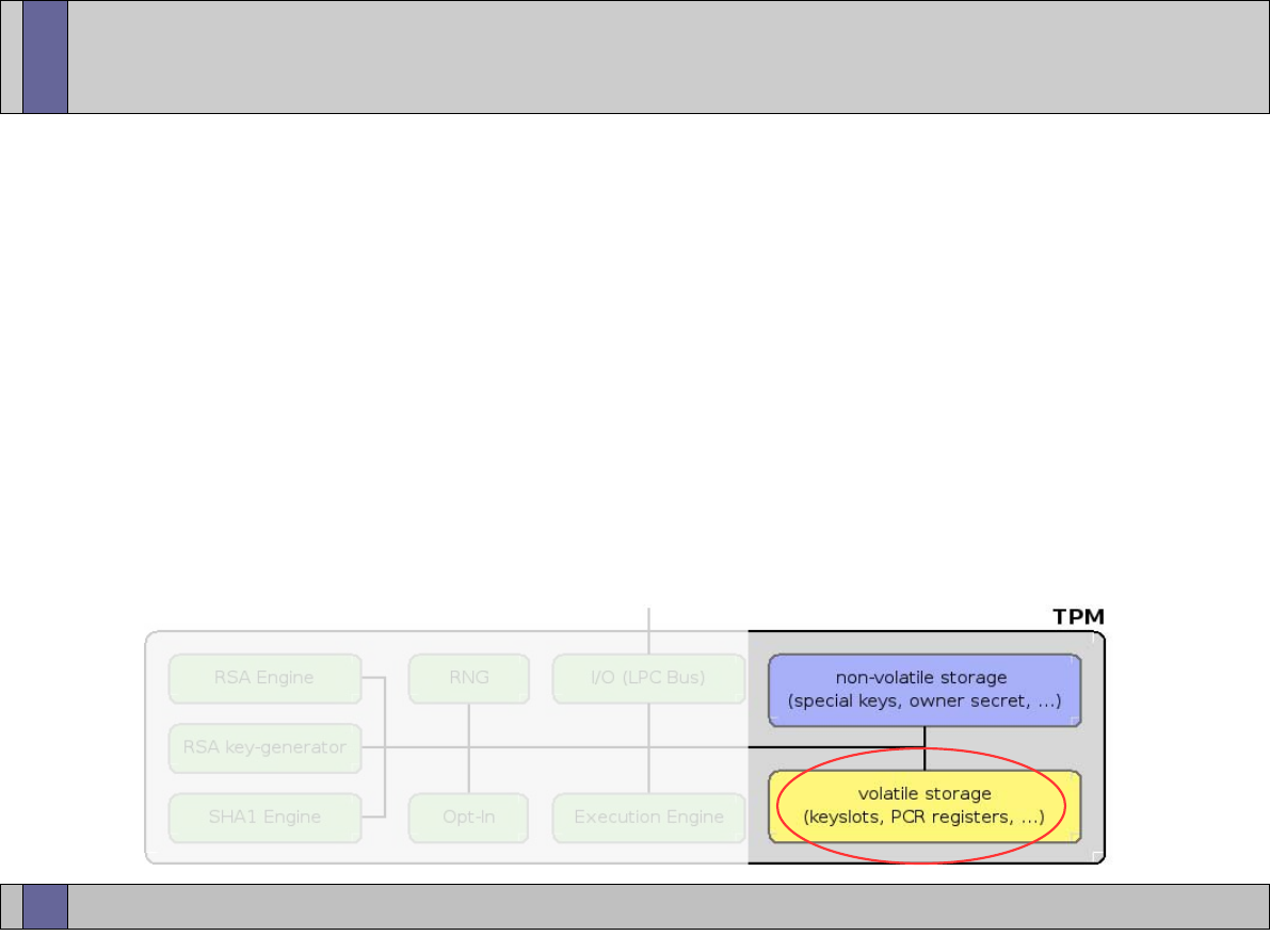
Trusted Computing Labs, IAIK TU Graz
13
TPM Internals
●
Platform Configuration Registers (PCRs)
–
PCR is a 160 bit storage location for integrity measurements
–
shielded location inside TPM
–
values are not set or overwritten but extended
PCR[i] = SHA-1(PCR[i] || newMeasurement)
–
PCR extends are not commutative (i.e. measuring A then B does not
result in the same PCR value as measuring B then A)
–
PCRs can keep track of unlimited number of measurements
–
TPM 1.1: 16 PCRs, TPM 1.2: 24 PCRs
–
static PCRs: reset only at boot time
–
dynamic PCRs: PCRs above index 16
●
reset can only be triggered by some
secure mechanism (D-RTM;
lecture on LaGrande Technology)
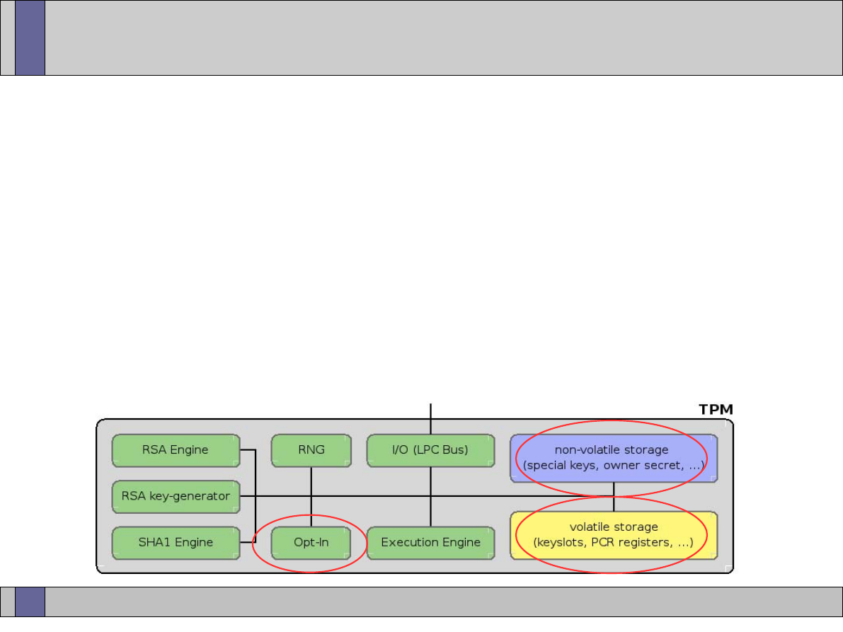
Trusted Computing Labs, IAIK TU Graz
14
TPM Internals
●
Volatile Memory
–
key slots: to use a TPM key it has to be loaded into the TPM
(remember: protected capabilities operate on shielded locations)
●
Non-Volatile Memory
–
special keys (Endorsement Key (EK) and Storage Root Key (SRK),
owner secret, ...
–
Endorsement Key Certificate (details follow in later lecture)
●
Opt-In: Platform owner can decide whether or not he wants to
make use of the TPM

Trusted Computing Labs, IAIK TU Graz
15
TPM Internals
●
Power Detection
–
TPM must be notified of all power changes
–
at some point in POST TPM gets notified that actions that require
physical presence have to be disabled
●
Symmetric Encryption for secrets
–
XOR
●
HMAC Engine
–
keyed hash function
–
provides proof of authentication data knowledge
–
proof that received command was not modified (integrity)

Trusted Computing Labs, IAIK TU Graz
16
Taking Ownership of a TPM
●
TPM is shipped in "unowned" state
●
to make proper use of TPM, platform owner has to execute
"TakeOwnership" operation
●
setting owner password - inserting a shared secret into the TPM
(stored in shielded location; non volatile memory)
●
certain TPM operations require owner authorization
●
physical presence allows access to certain (otherwise owner
protected) TPM functionality; does not reveal any TPM secrets (e.g.
ownership password can not be revealed using physical presence)
–
ForceClear allows to "clear" the TPM using physical presence
●
Storage Root Key (SRK) is created as part of TakeOwnership
●
(private) SRK is stored inside the TPM and never leaves it
●
password required for SRK usage can be set

Trusted Computing Labs, IAIK TU Graz
17
Clearing a TPM
●
resetting the TPM to the factory defaults
●
clearing requires owner secret or physical presence (ForceClear)
●
there are no mechanisms to recover a lost TPM owner password
●
tasks executed when clearing the TPM
–
invalidation of the SRK and thereby all data protected by the SRK;
note: no data blobs are touched but there simply is no way anymore
to decrypt them
–
invalidation of the TPM owner authorization value
–
reset of volatile and non-volatile memory to factory defaults
–
EK is NOT affected
–
PCR values are undefined after clear (reboot required)
●
ForceClear is only available during boot (and disabled thereafter)
●
OwnerClear can also be disabled (permanent; ForceClear required)
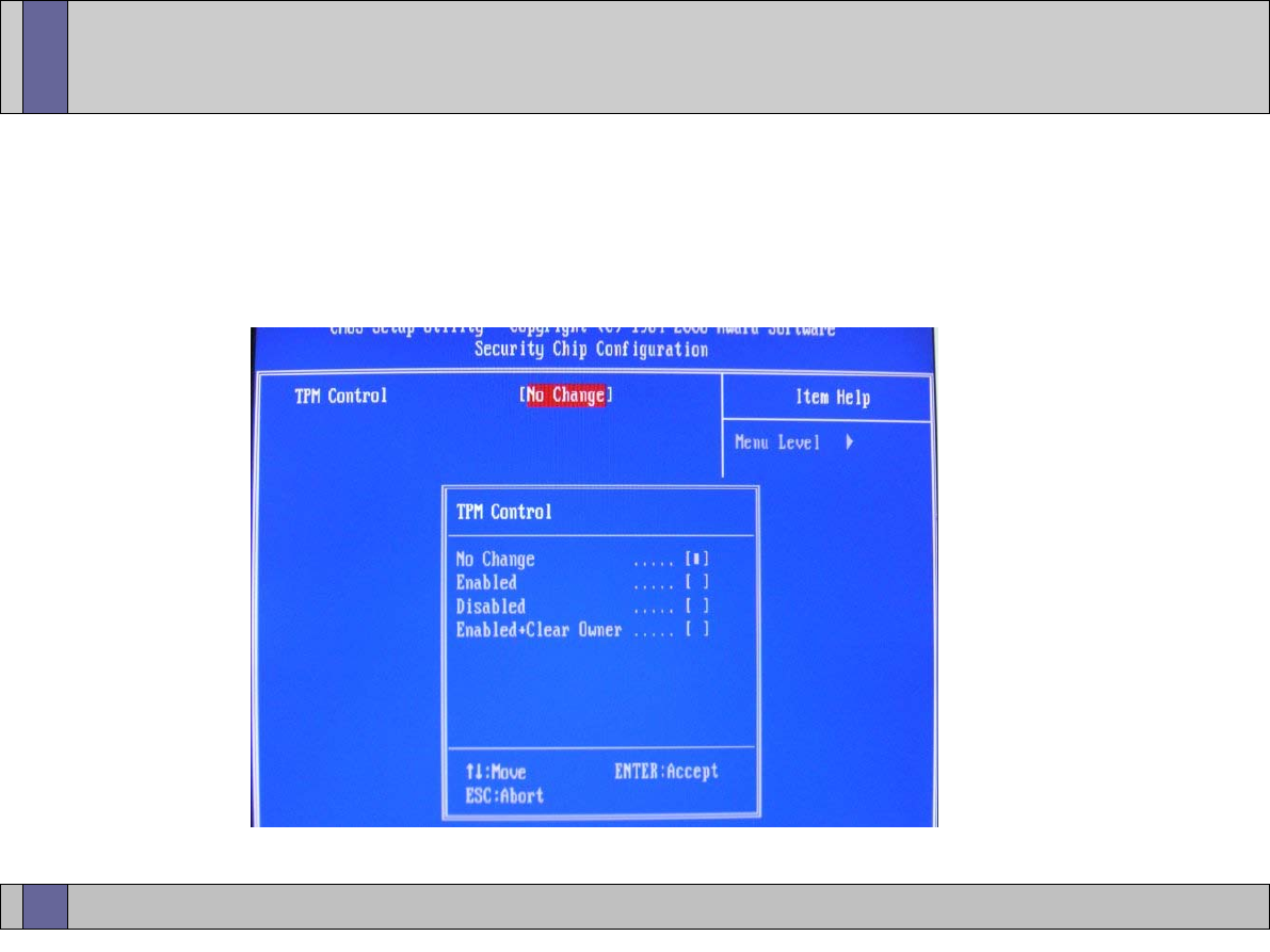
Trusted Computing Labs, IAIK TU Graz
18
TPM BIOS control
●
TCG compliant BIOS allows to ForceClear a TPM
●
TCG compliant BIOS allows to change TPM status
(disabled/enabled)

Trusted Computing Labs, IAIK TU Graz
19
TPM Keys
●
Endorsement key (EK)
–
unique platform identity
–
details are discussed later in the context of AIKs and Attestation
●
Storage Root Key (SRK)
–
2048 bit RSA key
–
is top level element of TPM key hierarchy
●
Storage Keys
–
RSA keys used to wrap (encrypt) other elements in the TPM key
hierarchy
●
Signature Keys
–
RSA keys used for signing operations
–
must be a leaf in the TPM key hierarchy

Trusted Computing Labs, IAIK TU Graz
20
TPM Keys
●
Binding Keys
–
key used for binding operations (TPM_Bind, TPM_Unbind)
●
Legacy Keys
–
can be used for both, signing and binding
–
usage of this type of key is not recommended (use keys tagged for
the specific purpose instead)
●
Protection of Keys
–
usage secret: has to be provided for all operations that make use of
a TPM key
–
migration secret: has to be provided when migrating a key between
different platforms (more details on migration in later sections)
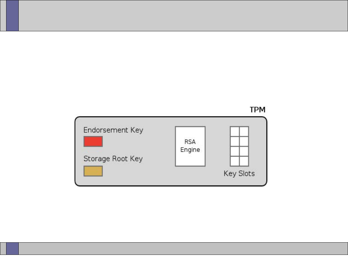
Trusted Computing Labs, IAIK TU Graz
21
Creating TPM Keys
●
Endorsement Key and Storage Root Key are the only keys
permanently stored inside the TPM
●
TPM keys are generated inside the TPM
●
to use a TPM key, it has to be loaded into the TPM
●
amount of TPM key slots is limited
●
management of key slots is done in software (TSS)
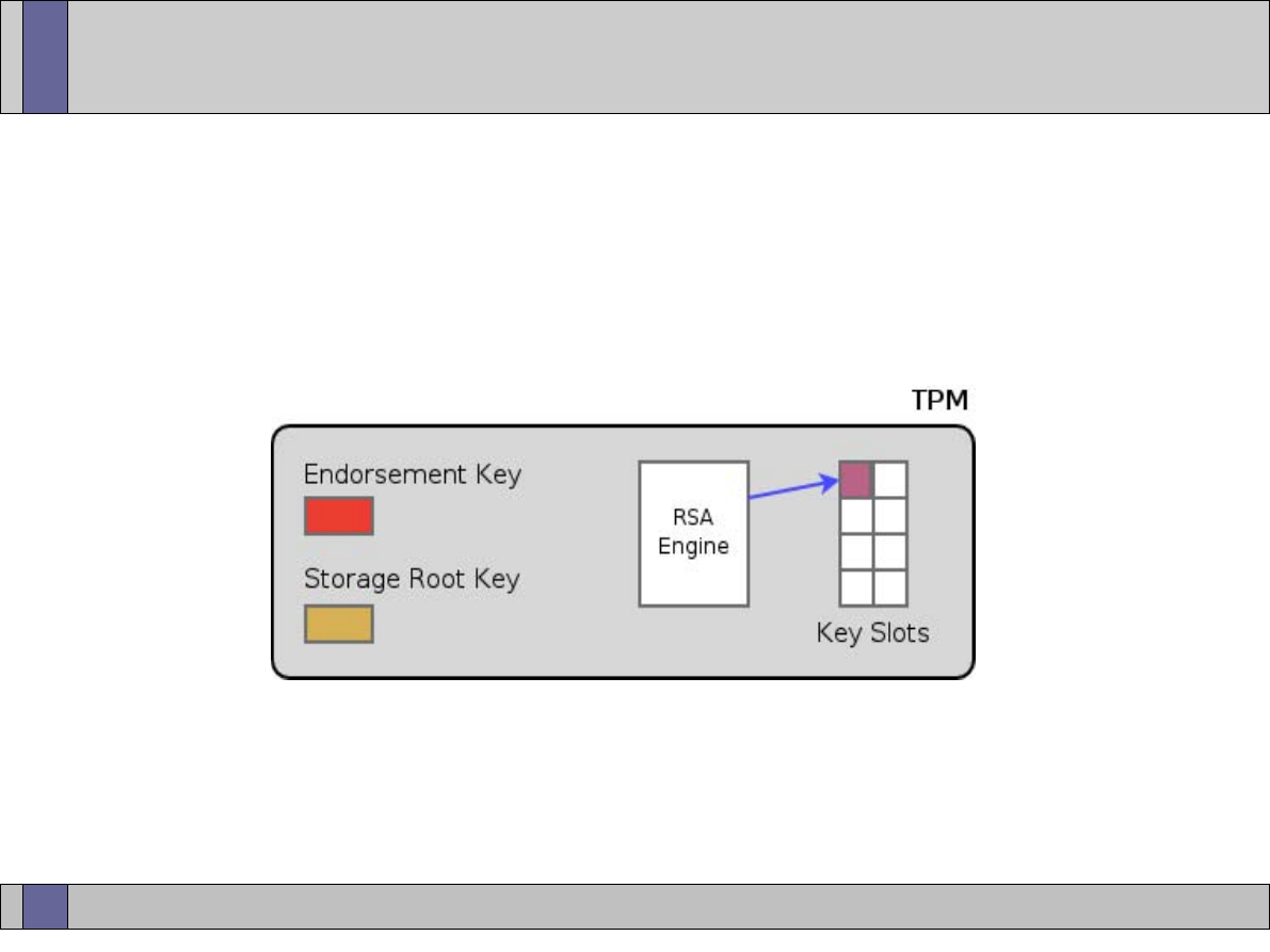
Trusted Computing Labs, IAIK TU Graz
22
Creating TPM Keys
●
RSA Engine creates a new RSA key
●
to create a key pair, a parent key has to be specified
●
amount of key slots inside the TPM is limited -> a mechanism is
required to (securely) swap out keys from the TPM
●
if a key is exported from the TPM its private part never leaves the
TPM in plain: it is encrypted with its public parent key

Trusted Computing Labs, IAIK TU Graz
23
TPM Key Hierarchy
●
When moving out keys from a TPM a key hierarchy is established.
●
Whenever a key is exported from the TPM, its private part is
encrypted using the public key of the parent.
In TCG terminology the child key is wrapped using the parent key.
●
Since the parents private key (required to load/decrypt the child
key) never leaves the TPM in plain, the private key of a TPM can
never be decrypted/used outside of the TPM.
●
The private SRK, sitting at the top level of the key hierarchy, is
never exported from the TPM.
●
Storage keys form the nodes of the key hierarchy while signing
keys always are leaves.
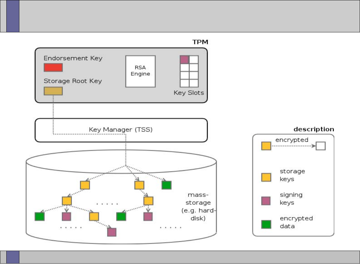
Trusted Computing Labs, IAIK TU Graz
24
TPM Key Hierarchy
●
key hierarchy with
SRK as root
●
private SRK never
leaves the TPM
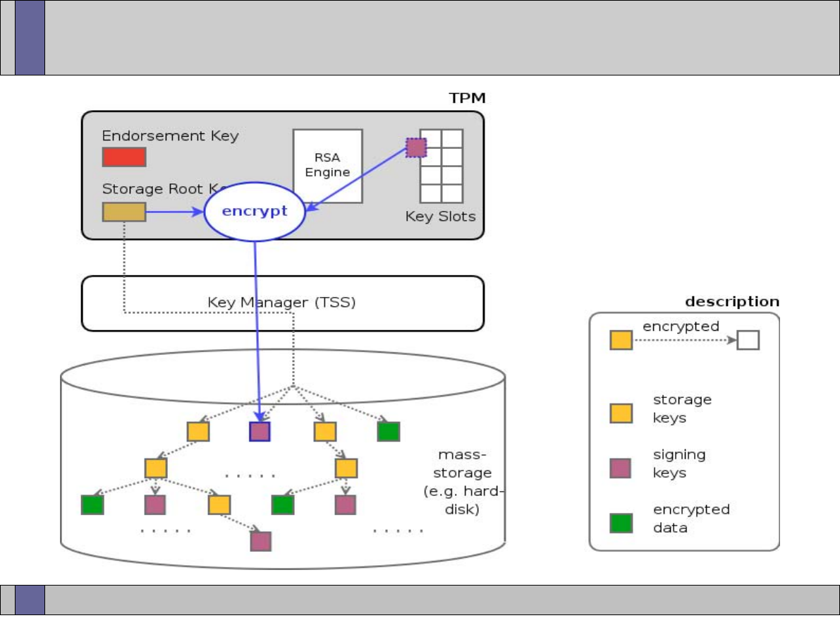
Trusted Computing Labs, IAIK TU Graz
25
Unloading TPM Keys
●
exporting key blob
from TPM
●
private part is
encrypted with public
parent key before
key blob leaves TPM
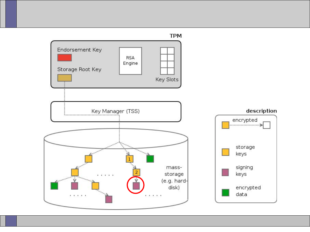
Trusted Computing Labs, IAIK TU Graz
26
Loading TPM Keys
●
task: load signing key into
TPM to use it for signing
operation
●
establish entire key chain
up to SRK
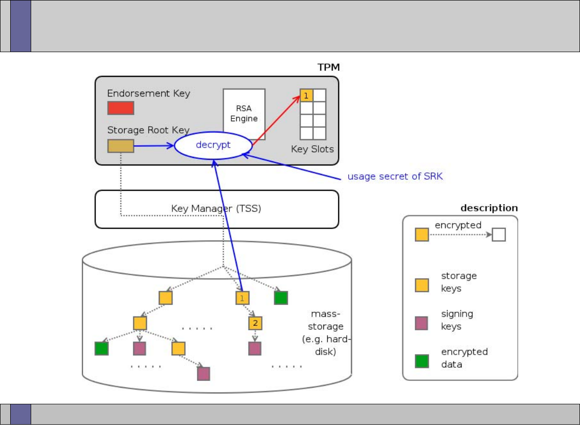
Trusted Computing Labs, IAIK TU Graz
27
Loading TPM Keys
●
decrypt private key of
storage key #1 using the
private SRK
●
requires SRK usage secret
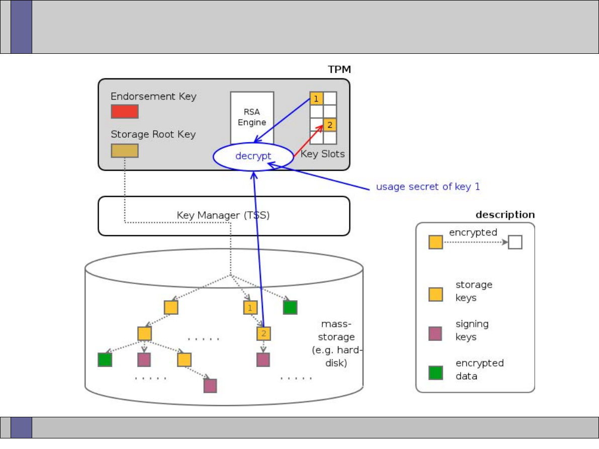
Trusted Computing Labs, IAIK TU Graz
28
Loading TPM Keys
●
decrypt private key of
storage key #2 using the
storage key #1
●
requires key #1 usage
secret
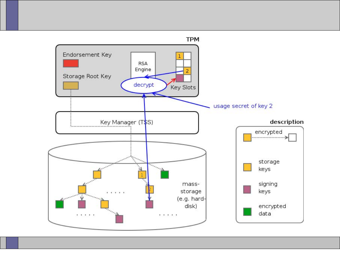
Trusted Computing Labs, IAIK TU Graz
29
Loading TPM Keys
●
decrypt private key of
signing key using the
storage key #2
●
requires key #2 usage
secret

Trusted Computing Labs, IAIK TU Graz
30
Roots of Trust
●
Root of Trust: “a hardware or software mechanism that one
implicitly trusts”
●
Root of Trust for Measurement (RTM)
–
uses PCRs to record the state of a system
–
static entity like the PC BIOS or dynamic entity (e.g. LT)
●
Root of Trust for Reporting (RTR)
–
entity trusted to report information accurately and correctly
–
uses PCRs and RSA signatures to report the platform state to
external parties in an unforgeable way
●
Root of Trust for Storage (RTS)
–
entity trusted to store information without interference leakage
–
uses PCRs and RSA encryption to protect data and ensure that data
can only be accessed if platform is in a known state

Trusted Computing Labs, IAIK TU Graz
31
Root of Trust for Measurement
●
goal: measure system state into PCRs
●
using PCRs a communication party can be convinced that the
system is in some known state
●
system users are NOT prevented from running any software
they want
●
but the execution is logged and can not be denied
●
problem: some anchor is needed to start the measurements
from -> Root of Trust for Measurement
●
static RTM: part of the BIOS
●
dynamic RTM: provided by technologies such as LaGrande
(intel) or Pacifica (AMD)
covered in later lectures

Trusted Computing Labs, IAIK TU Graz
32
Root of Trust for Measurement
●
From the RTM the trust is extended to other system components.
This concept is called transitive trust.
●
involved steps:
–
measure (compute the hash value of) the next entity: e.g. the BIOS
measures the OS loader
–
the measurement is extended into one of the TPMs PCRs
–
control is passes to the measured entity
●
This process is continued for all components of a system up to user
level applications.
●
PC client specifications defines which PCRs are used for what
●
note 1: measurements change with system updates and patches
●
note 2: number of measurements can get very large (already for
average systems)
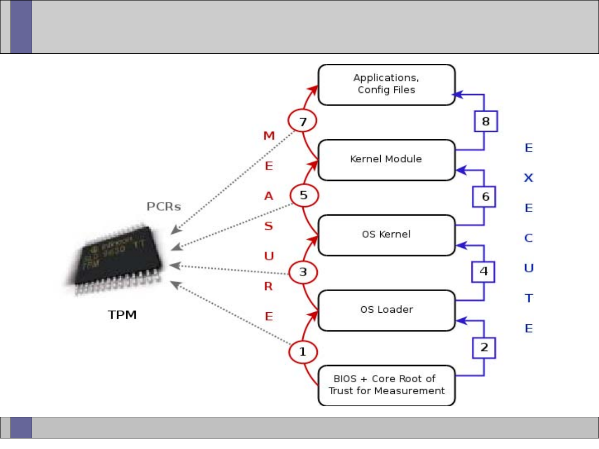
Trusted Computing Labs, IAIK TU Graz
33
Chain of Trust

Trusted Computing Labs, IAIK TU Graz
34
PCR Event Log
●
Together with PCR extensions also PCR event log entries can be
made.
●
A log entry contains the PCR number, the value that was extended
into the PCR and a log message (giving details what was
measured).
●
The event log does not need to be protected by the TPM and
therefore is managed on external mass storage (managed by TSS).
●
The event log can be used to validate the individual steps that lead
to the current PCR value.
–
calculate the extends in software starting at the beginning of the log
–
compare the result to the PCR value in the TPM
–
if the values match the verifier has assurance that the log was not
tampered with
●
PCR content is digitally signed inside the TPM (see Attestation)

Trusted Computing Labs, IAIK TU Graz
35
Root of Trust for Reporting
●
RTR is a mechanism to securely report that state of a platform to a
third party. The idea is to digitally sign the PCR values inside the
TPM and send the signature to the requester.
●
Endorsement Key (EK) forms the Root of Trust for Reporting (RTR)
–
2048 bit RSA key contained inside the TPM
–
private part never leaves the TPM (only exists in shielded location)
–
EK is unique for every TPM and therefore uniquely identifies a TPM
–
typically generated by TPM manufacturer in the fab either inside the
TPM or generated off-chip and then injected (private EK is exposed)
–
The EK is backed by an EK certificate typically issued by the TPM
manufacturer. The EK certificate guarantees that the key actually is
an EK and is protected by a genuine TPM.
–
EK can not be changed or removed

Trusted Computing Labs, IAIK TU Graz
36
Attestation Identity Keys
●
Uniqueness of the EK would be a privacy problem if the EK were
used directly in digital signature operations. All signatures done
with the EK could be tracked back to one single machine.
●
Therefore signing the PCRs using the EK and thereby proving that
the PCR values are protected by a TPM is not an option.
●
Attestation Identity Keys (AIKs) have been introduced as alias keys
for the EK. The AIKs are designed to provide privacy to users.
●
Attestation Identity Keys (AIKs)
–
2048 bit RSA keys
–
provides a mechanism to ensure that one is communicating with a
TPM but not which TPM
–
signature key that signs information generated inside the TPM
–
number of AIKs is not limited
–
regularly change AIKs (per service, per transaction, ...)

Trusted Computing Labs, IAIK TU Graz
37
Obtaining AIKs
●
when signing data with an AIK, the verifier wants assurance that
the key is a TPM protected key
●
AIKs are backed by a certificate that vouches for the fact that the
AIK is such a TPM protected key
●
Privacy CA: trusted third party that issues certificates for AIKs
●
basic AIK cycle
–
creates AIK key inside the TPM
–
AIK request data plus certificates are sent to PrivacyCA
–
PrivacyCA examines the supplied data
–
if PrivacyCA is convinced that the AIK is a TPM key it issues a
certificate stating that fact
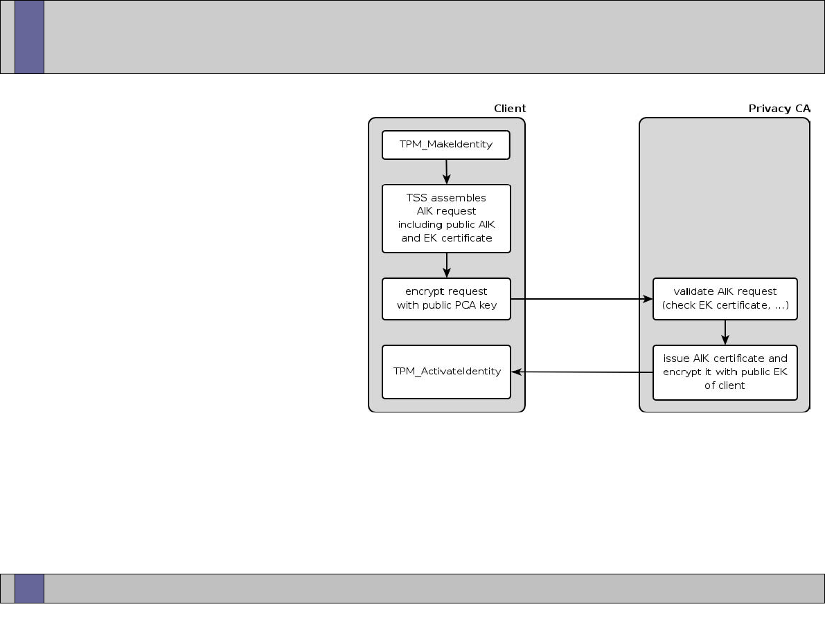
Trusted Computing Labs, IAIK TU Graz
38
Basic AIK cycle
●
client creates a new AIK
key pair inside the TPM
(TPM_MakeIdentity)
●
TSS assembles AIK request
–
TPM EK certificate
–
public AIK
–
...
●
AIK request is encrypted
with public key of PCA
●
PrivacyCA validates the AIK
request; checks EK certificate, ... If PCA is convinced that the AIK is
a proper TPM key it issues an AIK certificate. PCA response is
encrypted with public EK -> only the requester can read it.
●
client activates AIK and stores AIK certificate

Trusted Computing Labs, IAIK TU Graz
39
Attestation
●
goal: prove to an outside entity that the system is in a specific
state
●
involved steps
–
requester specifies the set of PCRs he is interested in and supplies a
nonce
–
client digitally signs the requested PCRs and the nonce inside the
TPM using an AIK
–
signed data plus AIK certificate are sent to requester
–
requester checks the digital signature (using AIK certificate) and the
nonce (to ensure freshness)
–
requester contacts PrivacyCA to determine the state of the AIK
certificate
–
depending on the outcome (PCRs as expected by the requester,
signature key is a TPM key, ...) requester decides if he wants to
communicate with the client or not
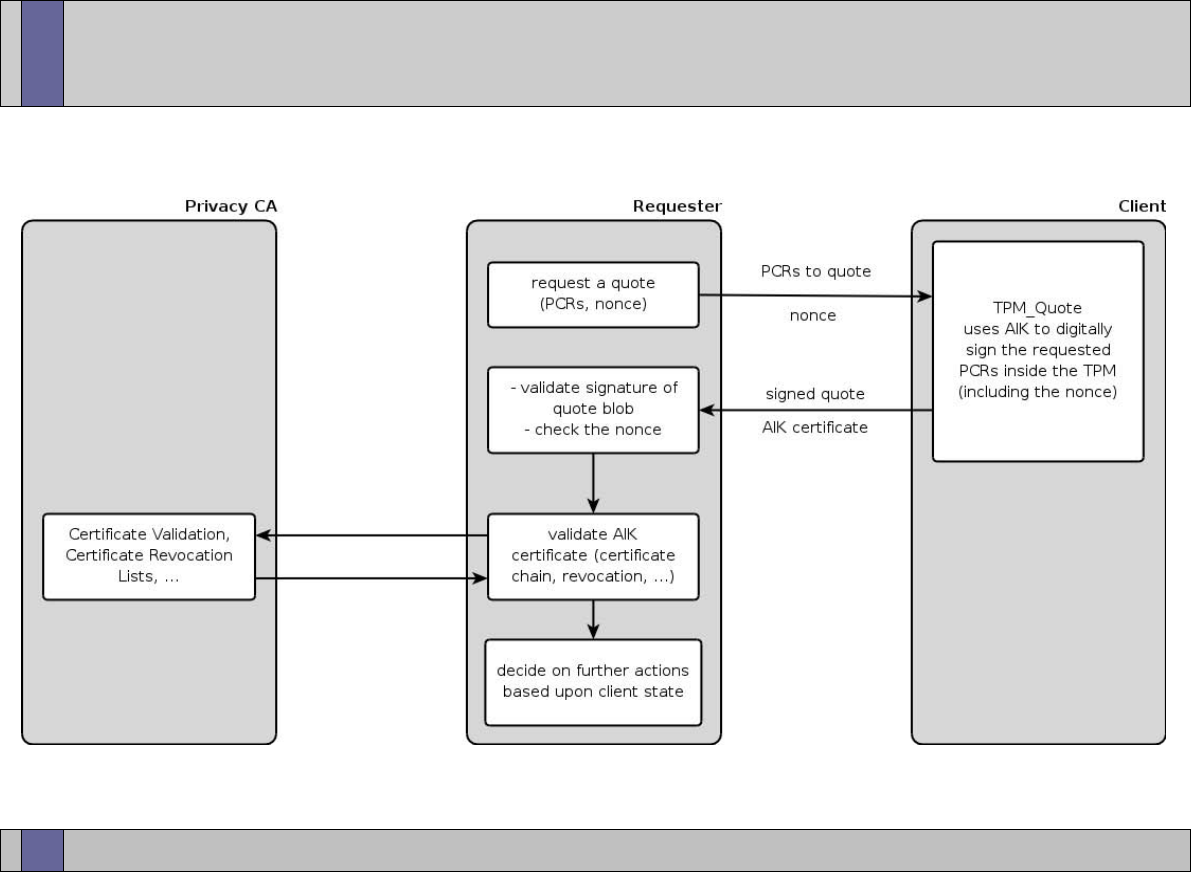
Trusted Computing Labs, IAIK TU Graz
40
Attestation

Trusted Computing Labs, IAIK TU Graz
41
Certifying Keys
●
certifying keys = TPM makes statement that “this key is held in a
TPM-shielded location, and it will never be revealed” (when using
an AIK to certify the key!)
–
certifying essentially means to sign the hash of the public key and
related key parameters
●
AIKs can certify only non-migratable keys (exception CMKs)
–
challenger must trust the TPM manufacturer
–
to validate a certified key the AIK credential can be used (verifier has
to trust the policy of the PrivacyCA)
–
for keys certified with an AIK, the user can ask a CA to issue a
certificate with a special extension (details follow in later lecture)
●
normal singing keys and legacy keys can certify migratable and
non-migratable keys
–
usefulness of this type of certification highly depends on the trust in
the signing/legacy key

Trusted Computing Labs, IAIK TU Graz
42
Root of Trust for Storage
●
SRK is the root of the TPM key hierarchy and never leaves the TPM
●
use of TPM keys for encrypting data and keys
●
two flavors:
–
without using PCRs: bind/unbind
–
with using PCRs: seal/unseal
●
binding
–
happens outside of the TPM
–
encrypt data with the public part of a TPM key
–
only the TPM the key pair belongs to can decrypt the data
remember: private key can only be used inside the TPM
–
binding to a specific TPM: us a non-migratable binding key
●
unbinding
–
decryption of bound data inside the TPM using the private key

Trusted Computing Labs, IAIK TU Graz
43
Root of Trust for Storage
●
sealing
–
a way to combine measurements (PCR content) and external data
–
encrypt externally provided data with reference to a specific PCR
state
–
only the TPM that sealed the data can do the unseal (ensured by
including a nonce that only is known to this specific TPM)
–
PCR values specified do not have to be the platforms current PCR
values but can be some other (future) PCR values
–
using a storage key (or legacy key)
●
unsealing
–
load key that was used for sealing into TPM
–
decrypt sealed blob inside TPM
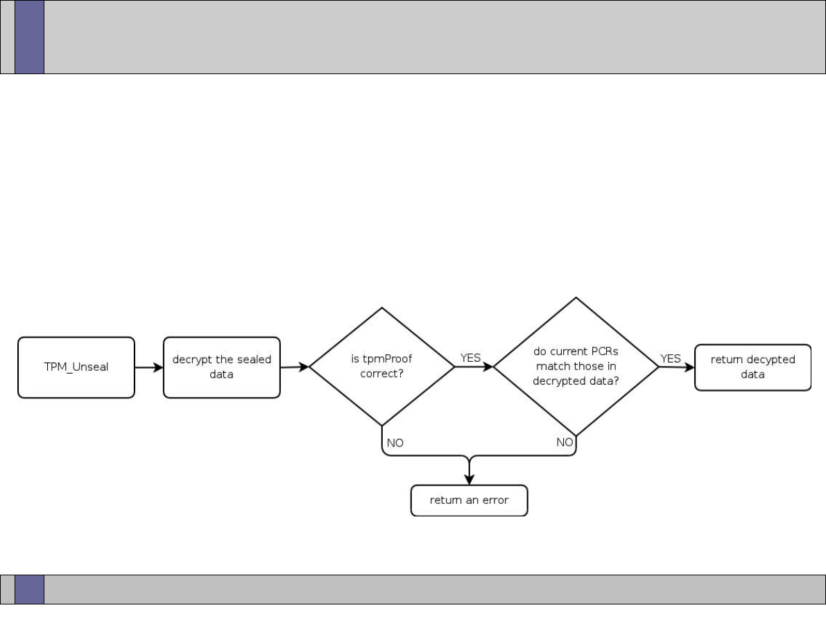
Trusted Computing Labs, IAIK TU Graz
44
Root of Trust for Storage
●
unsealing (cont.)
–
TPM checks the tpmProof included in the internal data: if the nonce
does not match the one of the TPM it returns an error
–
if the specified PCR values do not match the platforms current PCR
values an error is returned

Trusted Computing Labs, IAIK TU Graz
45
PCRs revisited
●
Summary of PCR usage scenarios
–
attestation of platform state (TPM_Quote)
–
protecting data (TPM_Seal/TPM_Unseal)
–
specify set of PCRs upon key creation: key is only usable if these
PCRs are present
●
Collection of measurements is done outside of the TPM by the
platform (chain of trust starting at the RTM).
●
problematic issues:
–
chain must not be broken
–
what to measure (binaries, configuration files, scripts, ...)
–
how to handle system updates?
–
pool of measurement values can become very large
●
ongoing research (e.g. property based attestation)

Trusted Computing Labs, IAIK TU Graz
46
Low-Level TPM Interaction
●
TPM specification defines a set of basic and complex types
–
definitions are in C style
–
primitive types: BYTE, BOOL, UINT16, UINT32
–
complex types are defined as C structures (typically prefixed with
TPM_ (in spec 1.2) or TCPA_ (in spec 1.1))
–
all type definitions, structures, constants and error codes are located
in part 2 of the specification
●
TPM has a byte stream oriented interface meaning that all
commands are serialized into byte arrays which are sent to the
TPM. The TPM response again is a byte stream that has to be
parsed.
●
TPM uses big endian byte order for multi-byte types (UINT16,
UINT32)
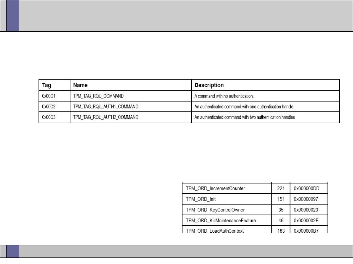
Trusted Computing Labs, IAIK TU Graz
47
TPM Command Header
●
all TPM Commands start with the same header block
–
TPM command tag (2 bytes)
–
parameter size (4 bytes)
●
total size of command (including header)
–
TPM command ordinal (4 bytes)
●
every TPM command has a unique command number (ordinal)
●
TPM_ORD_XXX (defined in TPM
specification part 2,
“TPM structures”)
images © by TCG (TPM specification)
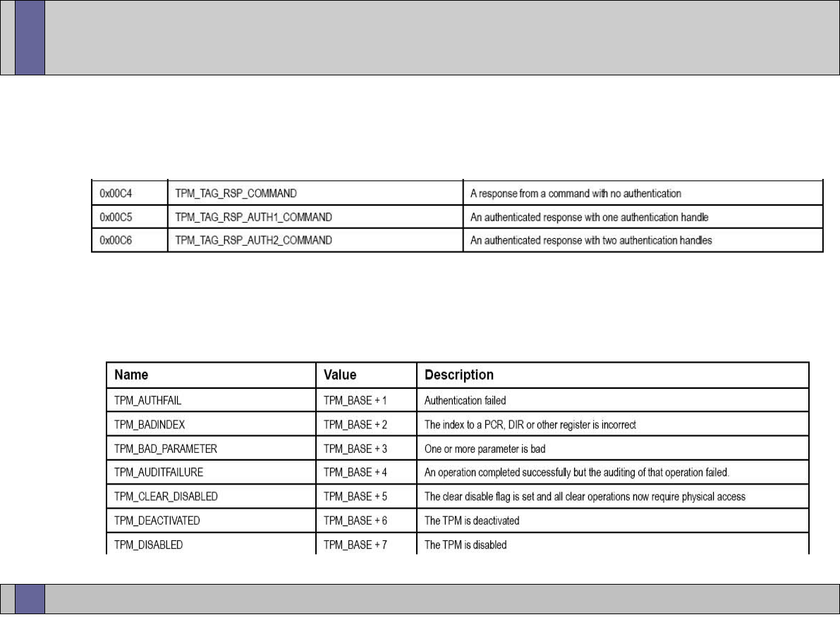
Trusted Computing Labs, IAIK TU Graz
48
TPM Command Response
●
TPM command responses also have a standard header:
–
TPM response tag (2 bytes)
–
parameter size (4 bytes)
–
TPM return code (4 bytes)
●
TPM_SUCCESS (0x0)
images © by TCG (TPM specification)
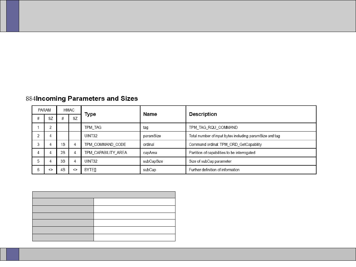
Trusted Computing Labs, IAIK TU Graz
49
TPM_GetCapability Command Example
●
non-authorized command (TPM_TAG_RQU_COMMAND)
●
gets information about a TPM (e.g. number of PCRs)
●
in the spec:
●
on the wire:
upper image © by TCG (TPM specification)
TPM_GetCapability Command
command tag
0x00 0xc1
... TPM_TAG_RQU_COMMAND
parameter size
0x00 0x00 0x00 0x16
... command size: 22 bytes (0x16)
ordinal
0x00 0x00 0x00 0x65
... TPM_ORD_GetCapability
capability area
0x00 0x00 0x00 0x05
... TPM_CAP_PROPERTY
sub-capability size
0x00 0x00 0x00 0x04
... sub capability size: 4 bytes
sub-capability area
0x00 0x00 0x01 0x01
... TPM_CAP_PROP_PCR
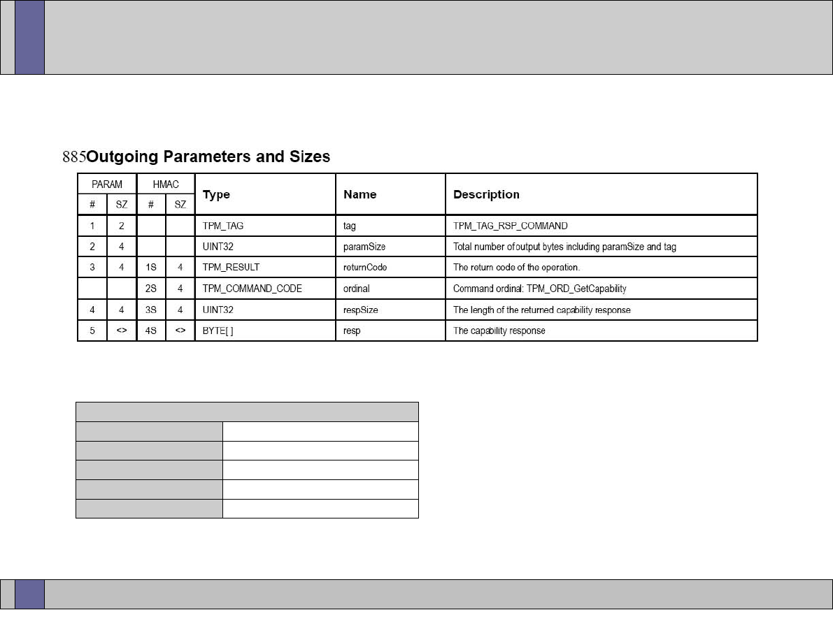
Trusted Computing Labs, IAIK TU Graz
50
TPM_GetCapability Response
●
in the spec:
●
on the wire:
TPM_GetCapability Response
command tag
0x00 0xc4
... TPM_TAG_RSP_COMMAND
parameter size
0x00 0x00 0x00 0x12
... response size: 18 bytes (0x12)
return code
0x00 0x00 0x00 0x00
... TPM_SUCCESS
response size
0x00 0x00 0x00 0x04
... response payload size: 4 bytes
response data
0x00 0x00 0x00 0x18
... response data: 0x18 ... 24 PCRs
upper image © by TCG (TPM specification)

Trusted Computing Labs, IAIK TU Graz
51
TPM Command/Object Authorization
●
many commands require the knowledge of authorization data
●
typically not commands themselves require authorization but the
objects the commands operate on (e.g. keys, encrypted data)
●
some commands require owner authorization
●
20 bytes shared secret (SHA-1 hash of the password) is required to
use protected objects
●
secret is stored together with TPM controlled objects in shielded
locations
●
owner and SRK secret are stored inside the TPM
note: TPM owner is no “super user” (e.g. has not access to all keys
without knowing their secret)
●
if the owner of an object (e.g. key) can provide the correct secret
(authData) it also can execute all TPM operations applicable to that
object

Trusted Computing Labs, IAIK TU Graz
52
●
TPM supports different authorization protocols depending on the
specific purpose
●
OIAP: Object Independent Authorization Protocol
–
supports authorization for arbitrary entities
–
session lives indefinitely until it is explicitly terminated
●
OSAP: Object Specific Authorization Protocol
–
supports an authentication session of a single entity
–
enables confidential transmission of new authorization information
●
ADIP: Authorization Data Insertion Protocol
–
used to insert new authorization information during the creation of a
new object
●
additional protocols to change authorization secrets
●
authorization protocols are based on the “rolling nonce” paradigm
TPM Authorization Protocols

Trusted Computing Labs, IAIK TU Graz
53
Rolling Nonce Paradigm
●
on session establishment the TPM creates a nonce called
“nonceEven” which is returned to the client
●
the client creates a new nonce called “nonceOdd”
●
the client includes the “nonceEven” received from the TPM and its
own “nonceOdd” in the next request sent to the TPM
●
the TPM validates the “nonceEven” contained in the request,
creates a new “nonceEven” and includes this new “nonceEven”
together with the “nonceOdd” from the client in its response
●
client validates the “nonceOdd” received in the response,
generates a new “nonceOdd”... and so on
●
Summary: each new input message contains a new nonceOdd and
each response contains a new nonceEven
●
rolling nonces are never used on their own but as part of an
authorization protocol
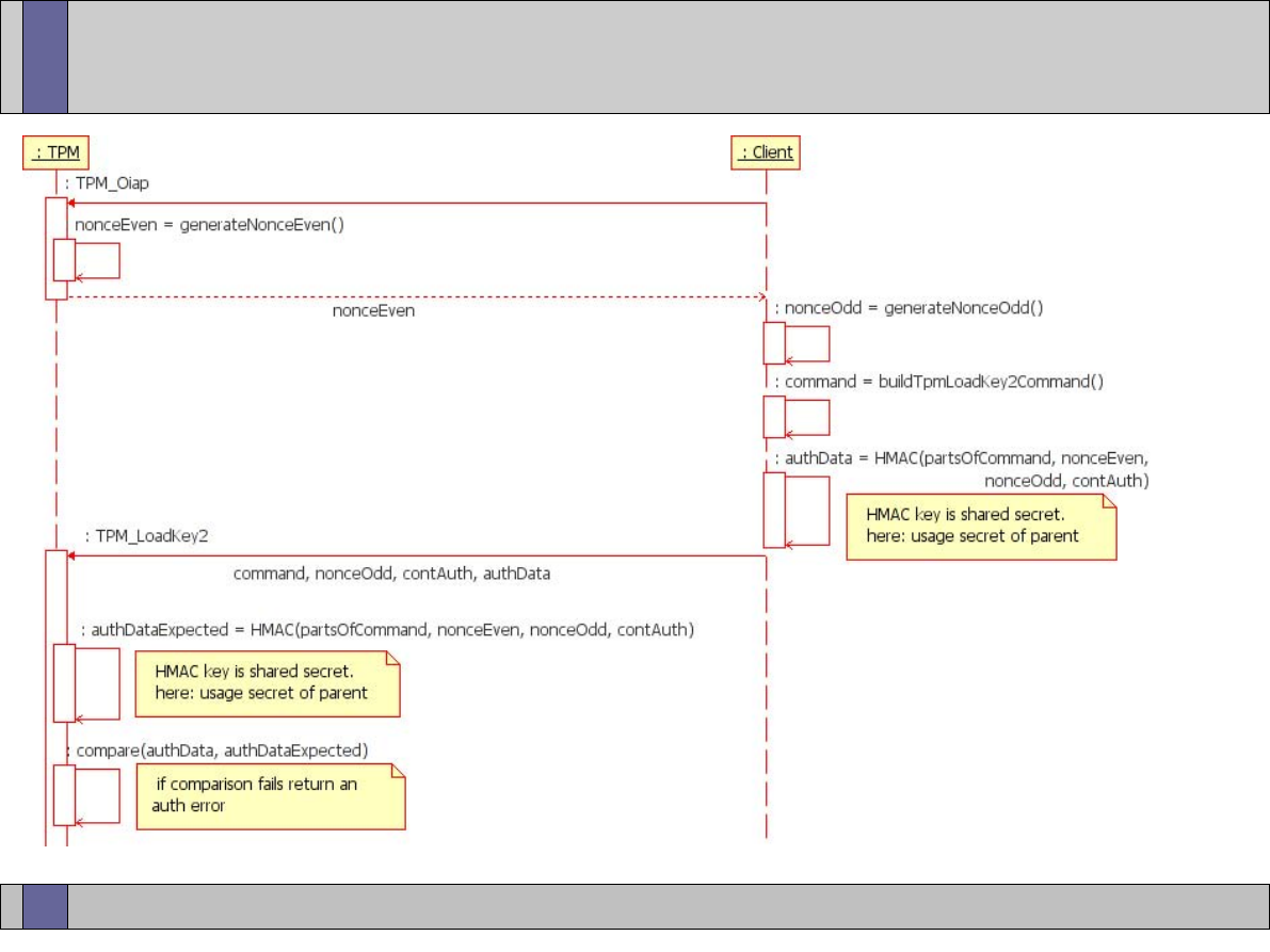
Trusted Computing Labs, IAIK TU Graz
54
Authorized Command Flow
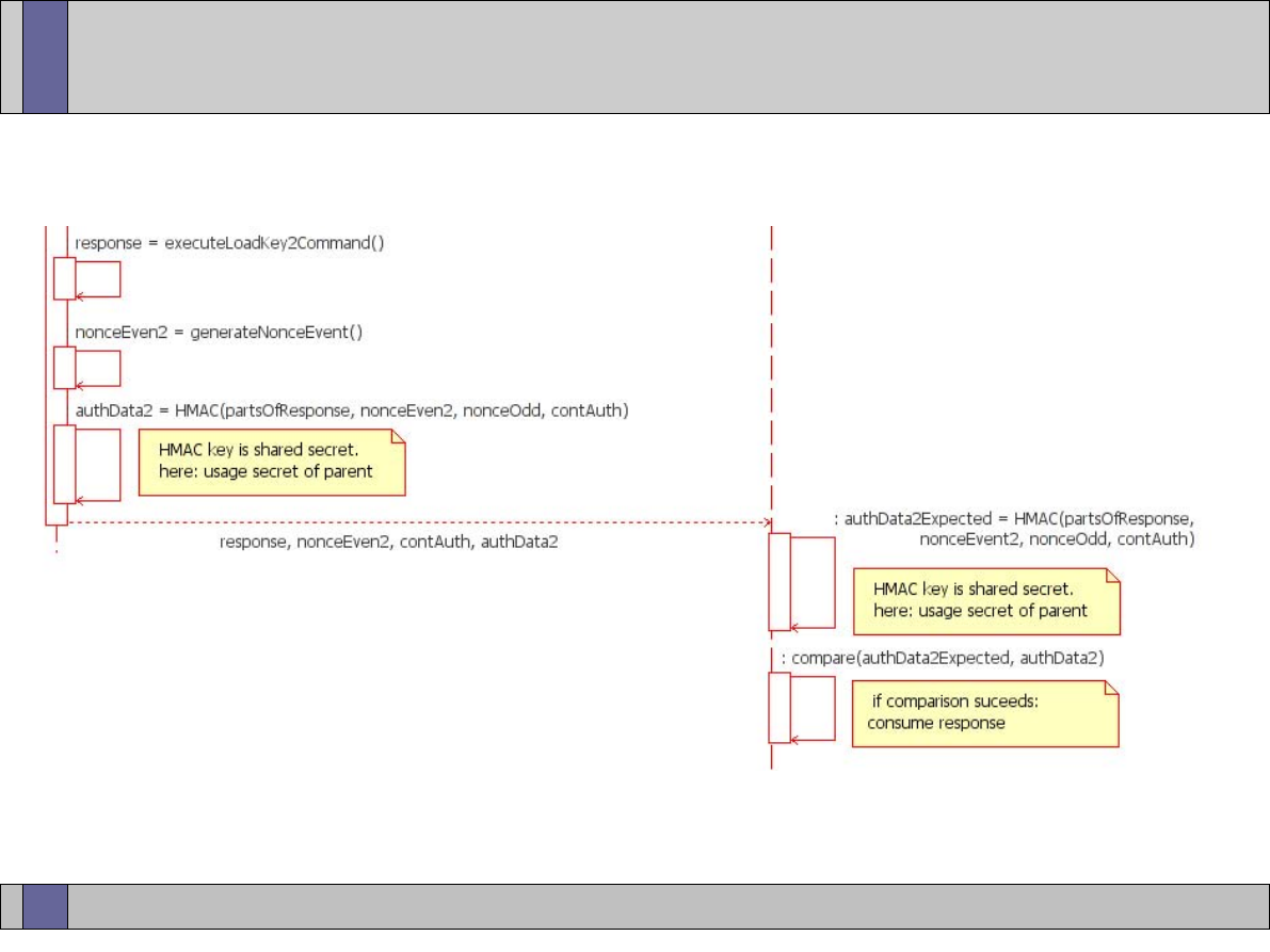
Trusted Computing Labs, IAIK TU Graz
55
Authorized Command Flow
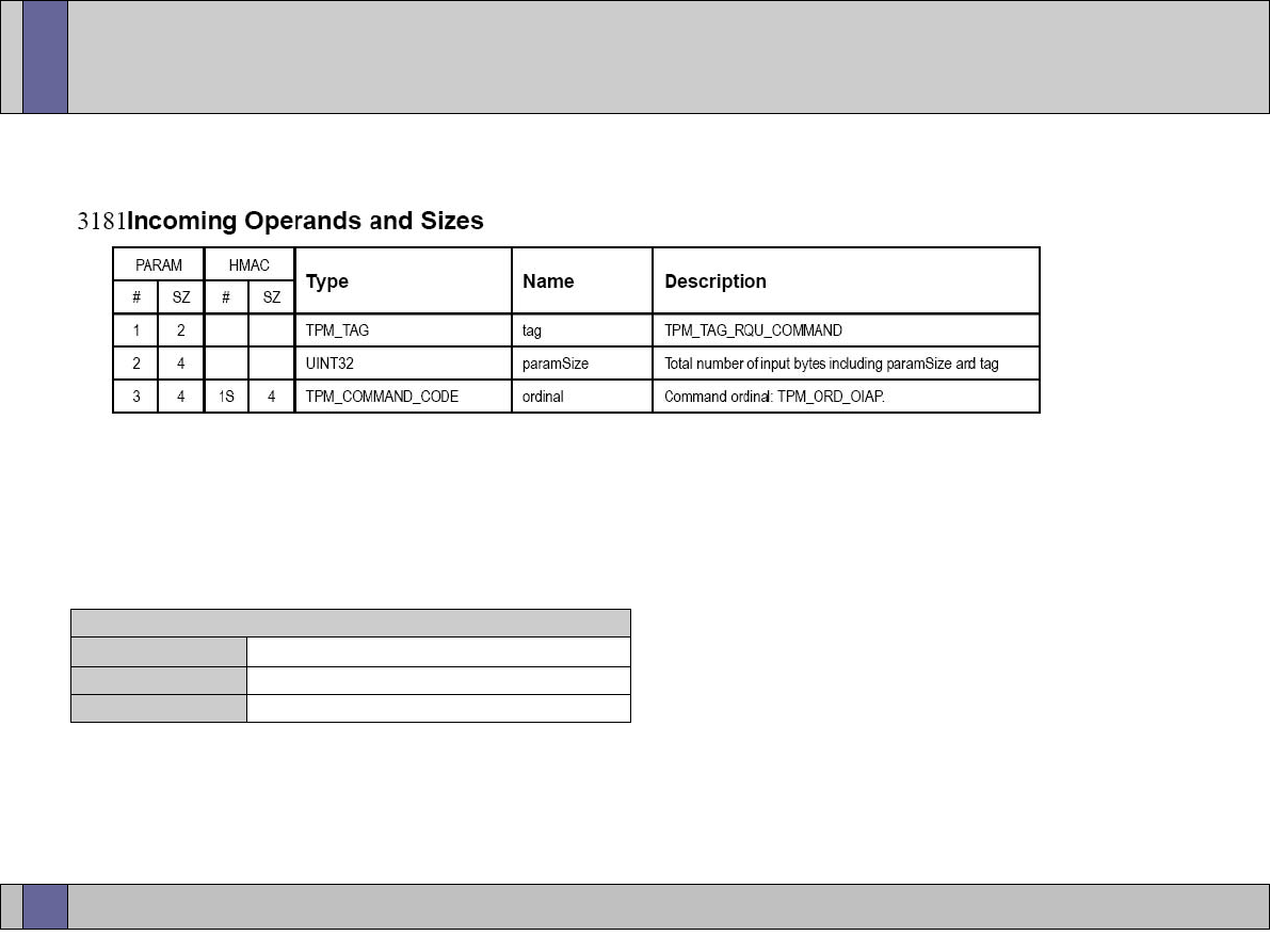
Trusted Computing Labs, IAIK TU Graz
56
TPM_OIAP Session Establishment
●
in the spec:
●
on the wire:
TPM_OIAP Command
command tag
0x00 0xc1
... TPM_TAG_RQU_COMMAND
parameter size
0x00 0x00 0x00 0x0a
... size: 10 bytes
ordinal
0x00 0x00 0x00 0x0a
... TPM_ORD_OIAP
upper image © by TCG (TPM specification)
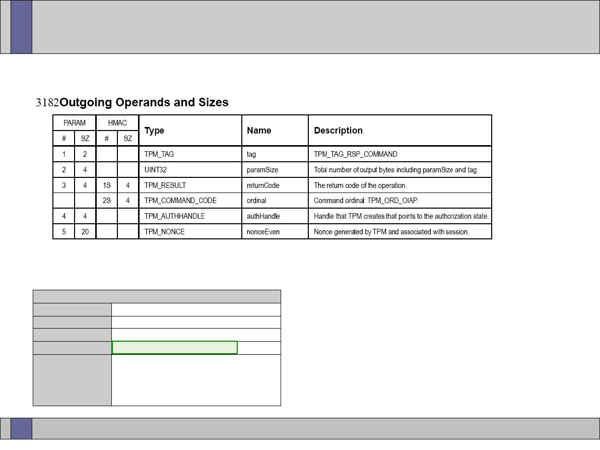
Trusted Computing Labs, IAIK TU Graz
57
TPM_OIAP Session Establishment
●
in the spec:
●
on the wire:
TPM_OIAP Response
command tag
0x00 0xc4
... TPM_TAG_RSP_COMMAND
parameter size
0x00 0x00 0x00 0x22
... size: 34 bytes
return code
0x00 0x00 0x00 0x00
... TPM_SUCCESS
authHandle
0x00 0xa6 0x8e 0xd7
... TPM authorization handle
nonceEven
0x32 0x78 0x2c 0x3d 0x4a
... nonceEven generated by the
0x97 0x67 0x66 0xc5 0x83
TPM (20 bytes)
0x59 0xf4 0x4b 0x41 0xf9
0x19 0x86 0xb5 0x34 0x6f
upper image © by TCG (TPM specification)
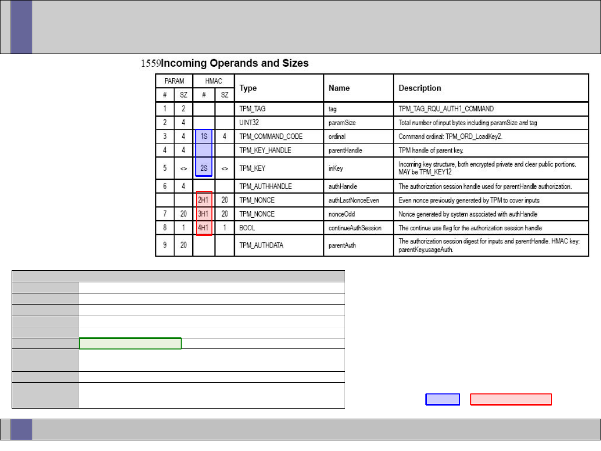
Trusted Computing Labs, IAIK TU Graz
58
TPM_LoadKey2 Command
●
in the spec:
●
on the wire:
command tag
0x00 0xc2
... TPM_TAG_RQU_AUTH1_COMMAND
parameter size
0x00 0x00 0x02 0x6a
... size: 618 bytes
ordinal
0x00 0x00 0x00 0x41
... TPM_ORD_LoadKey2
0x40 0x00 0x00 0x00
... handle of (loaded) parent key (here: TPM_KH_SRM)
...
...
0x00 0xa6 0x8e 0xd7
... OIAP session handle
0xcc 0x14 0xbe 0x7e 0x47 0x44 0x2b 0x8c 0x8a 0x26
...
0x82 0xab 0x2a 0x87 0x01 0x3f 0xa2 0xc2 0xea 0x69
0x00
...
0xec 0x3a 0x89 0x29 0x5b 0x78 0x31 0xff 0x2e 0x8b
...
0x09 0x88 0x78 0xa9 0x23 0x52 0xd0 0x07 0xb7 0x82
Tpm_LoadKey2 Command
parentHandle
inKey
instance of TPM_KEY struct
authHandle
nonceOdd
nonceOdd generated by the TSS
contAuthSess
continue (reuse) auth (OIAP) session
parentAuth
auth session digest
HMAC
K
(SHA1(1S || 2S) || 2H1 || 3H1 || 4H1)
k = parentKey.usageAuth (= SHA1 of parent secret)
upper image © by TCG (TPM specification)
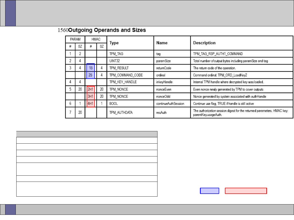
Trusted Computing Labs, IAIK TU Graz
59
TPM_LoadKey2 Command
●
in the spec:
●
on the wire:
TPM_LoadKey2 Response
0x00 0xc5
... TPM_TAG_RSP_AUTH1_COMMAND
0x00 0x00 0x00 0x37
... size: 55 bytes
0x00 0x00 0x00 0x00
... TPM_SUCCESS
0x05 0xaf 0x15 0xd0
... TPM key handle assigned to the loaded key
0xd4 0xb6 0x6a 0x6d 0x8a 0x53 0x39 0x02 0x20 0xf0
...
0xde 0xbb 0x9e 0x63 0x37 0x29 0x6d 0x2f 0x3b 0x2e
0x00
...
0x79 0x99 0xca 0x95 0x7d 0xef 0x3d 0xfb 0x74 0xa1
...
0x50 0x17 0xcf 0x41 0x83 0x03 0x92 0x0c 0xa9 0xdb
new nonceEven generated by the TPM
continue (reuse) auth (OIAP) session
auth session digest
HMAC
K
(SHA1(1S || 2S) || 2H1 || 3H1 || 4H1)
k = parentKey.usageAuth (= SHA1 of parent secret)
upper image © by TCG (TPM specification)

Trusted Computing Labs, IAIK TU Graz
60
Authorization Sessions
●
Authorization sessions established via TPM_OIAP or TPM_OSAP
remain active until they are terminated by setting
continueAuthSession to FALSE or calling TPM_FlushSpecific.
●
Authorization sessions are addressed by an authHandle (the same
way as keys are addressed by a key handle).
●
The available space for auth sessions is limited.
–
session management is done by the TSS
–
some 1.1 chips support auth session swapping
–
for 1.2 TPMs auth session swapping support is a requirement
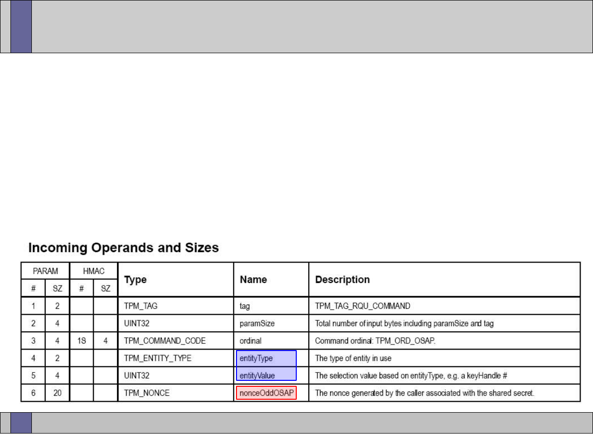
Trusted Computing Labs, IAIK TU Graz
61
Object Specific Authorization (OSAP)
●
OSAP authorization sessions are tied to a specific object (e.g. key)
while OIAP sessions can be used for arbitrary objects.
●
TPM_OSAP command: establishment of OSAP session
●
binding to an entity is done via entityType/entityValue
●
OSAP sessions have an additional pair of nonces (nonce[Odd|
Even]OSAP) use to calculate a shared OSAP secret
image © by TCG (TPM specification)
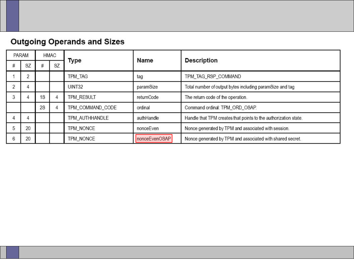
Trusted Computing Labs, IAIK TU Graz
62
Object Specific Authorization (OSAP)
●
Calculation of shared OSAP secret:
HMAC
k
(nonceEvenOSAP || nonceOddOSAP)
k = entitySecret (e.g. key usage secret)
●
The shared OSAP secret is then used as the HMAC key for the
actual operation (instead of the entitySecret).
●
An established OSAP session can only be used for the defined
entity.
image © by TCG (TPM specification)

Trusted Computing Labs, IAIK TU Graz
63
Authorization Data Insertion
●
TPM entities such as keys have an associated usage secret (and if
migratable, a migration secret)
●
when creating a new key, the key secrets must not be transmitted
to the TPM in plain -> they are XOR encrypted
●
establish an OSAP session using the parent of the new entity
XOR_KEY = SHA1(sharedOSAPsecret || nonceEven)
encAuth = XOR(newEntity.secret, XOR_KEY)
●
note: newEntity.secret is the SHA1 hash of the secret provided by
the user (i.e. the TPM stores all secrets as SHA1 hashes)
●
The encrypted authorization data (encAuth) is sent to the TPM as
part of the TPM command that creates the new entity (e.g. key)
●
The TPM computes the XOR_KEY the same way and then retrieves
the secret of the new entity that is stored together with this entity.

Trusted Computing Labs, IAIK TU Graz
64
Advanced TPM concepts
●
Overview
–
Key Migration and Certified Migratable Keys
–
Monotonic Counters and Timestamping
–
Non-Volatile Storage
–
Delegation
–
Transport Sessions
–
Maintenance
–
Localities (covered in later lecture on LaGrande Technology)
–
Direct Anonymous Attestation (covered in later lecture)
●
Many of those concepts have been introduced with TPM
specification 1.2.

Trusted Computing Labs, IAIK TU Graz
65
TPM Key Migration
●
basic migration scheme (TPM 1.1)
–
migrate RSA keypair KEY_A from TPM_A to TPM_B
–
parent of KEY_A is the SRK (i.e. private part of KEY_A is encrypted
with the public SRK of TPM_A)
–
storage key KEY_B of TPM_B to become new parent of KEY_A
–
prepare KEY_B by calling TPM_AuthorizeMigrationKey on TPM_B
–
transport the resulting public key structure to TPM_A
–
call TPM_CreateMigrationBlob using the public part of KEY_B on
TPM_A
–
TPM_A internally re-wraps KEY_A: decryption of the private part of
KEY_A using the private SRK and then encrypting using the public
part of KEY_B (requires knowledge of migration secret of KEY_A)
–
re-wrapped KEY_A can now be loaded into TPM_B (unwrapping it with
its new parent: KEY_B)
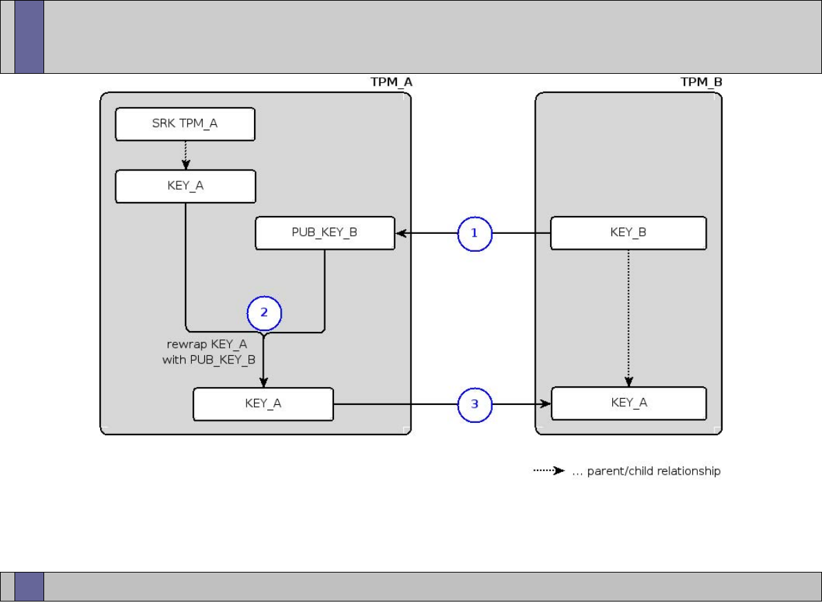
Trusted Computing Labs, IAIK TU Graz
66
Basic TPM Key Migration at a Glance
●
1
– transfer public part of KEY_B to TPM_A
●
2
– re-wrap private part of KEY_A using public part of KEY_B
●
3
– KEY_A can now be loaded into TPM_B (KEY_B, its parent, is a key of TPM_B)

Trusted Computing Labs, IAIK TU Graz
67
TPM Key Migration
●
keys that can not be migrated: EK, SRK, AIKs, Non-Migratable Keys
●
migratable keys have a migration secret
●
advanced key migration (TPM 1.2)
–
Certified Migration Keys (CMKs)
–
requires external 3
rd
parties:
●
Migration Selection Authority (MSA)
●
Migration Authority (MA)
–
so far no known implementation of this infrastructure (details on
MSA, and CMKs follow in a later lecture)
●
TPM Maintenance: vendor specific migration
–
optional TPM feature; vendor specific; requires owner authorization
–
allows to export all TPM data (migratory and non-migratory data)
–
useful in case of replacing sub-system components

Trusted Computing Labs, IAIK TU Graz
68
Monotonic Counters and Timestamps
●
Monotonic Counter
–
allows for 7 years of increments every 5 seconds
–
useful e.g. against replay attacks
●
Time Stamping
–
TPM offers time stamping mechanism
–
time stamps are not an universal time clock (UTC) value but the
number of timer ticks counted by the TPM
–
TPM has a tick session (started when TPM is powered on)
●
tick value, increment rate, session nonce (new at every power cycle)
–
TPM_TickStampBlob takes a digest to be signed with a TPM signing
key; current tick value and session nonce are included in signature
●
mechanism outside the TPM is required to associate the tick value
with an UTC value

Trusted Computing Labs, IAIK TU Graz
69
Non-Volatile Storage
●
TPM contains protected non-volatile storage
●
TPM Owner can define storage locations and their appropriate
access protection (e.g. requiring authorization for read/write,
coupling access to the platform state, ...).
●
stored entities addressed using indices
●
potential usage scenarios:
–
secure storage for certificates such as EK certificate
–
storage for early bootup stages where other forms of persistent
storage are not yet available

Trusted Computing Labs, IAIK TU Graz
70
Transport Sessions
●
a mechanism to protect information sent to and returned from the
TPM
●
data transmitted to/from the TPM is encrypted
●
sequence of commands: groups a set of commands and provides a
digital signature on all of the commands
–
these transport logs provide evidence that a series of operations
actually took place inside the TPM
●
exclusive transport sessions: any command outside of the session
causes the session to terminate

Trusted Computing Labs, IAIK TU Graz
71
Further Reading
●
Trusted Computing Group:
http://www.trustedcomputinggroup.org
Architecture Overview
https://www.trustedcomputinggroup.org/specs/IWG/TCG_1_0_Architecture_Overview.pdf
TPM Specification
https://www.trustedcomputinggroup.org/specs/TPM
●
Trusted Platform Basics – Using TPMs in Embedded Systems
Steven Kinney; Newnes/Elsivier
●
The Intel Safer Computing Initiative
Building Blocks for Trusted Computing
David Grawrock; intel press
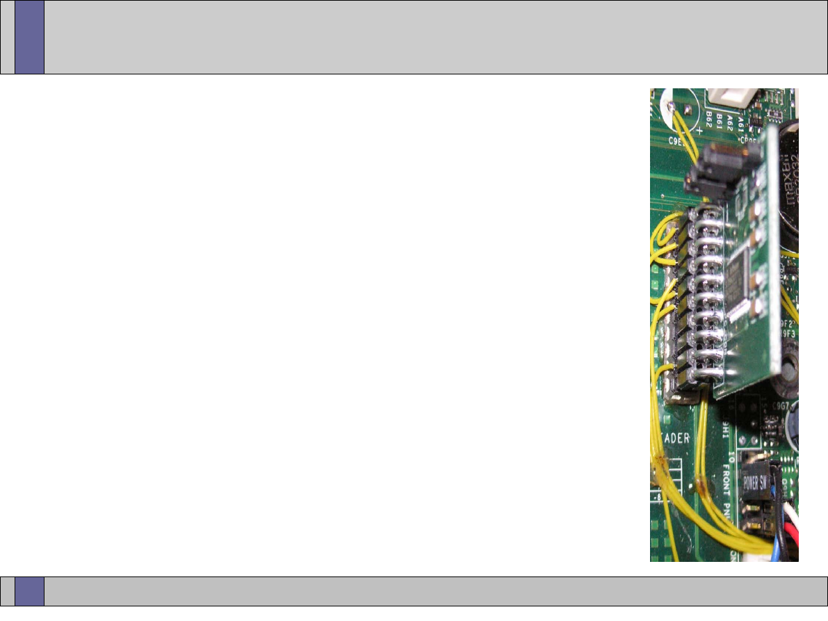
Trusted Computing Labs, IAIK TU Graz
72
Finally – Coming to an end
Questions?
Thank you very much
for your attention!
Trusted Computing Labs, IAIK TU Graz
73
Open_TC EC Contract No: IST-027635
●
The Open_TC project is co-financed by the EC.
contract no: IST-027635
●
If you need further information, please visit our
website www.opentc.net or contact the coordinator:
Technikon Forschungs- und Planungsgesellschaft mbH
Richard-Wagner-Strasse 7, 9500 Villach, AUSTRIA
Tel. +43 4242 23355 0
Fax. +43 4242 23355 77
Email coordination@opentc.net
The information in this document is provided “as is”, and no guarantee or
warranty is given that the information is fit for any particular purpose.
The user thereof uses the information at its sole risk and liability.
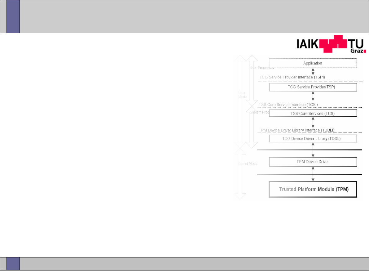
Trusted Computing Labs, IAIK TU Graz
1
Trusted Computing
TSS - TCG Software
Stack
Thomas Winkler <
thomas.winkler@iaik.tugraz.at
>
v20070319

Trusted Computing Labs, IAIK TU Graz
2
Overview
●
Introduction
●
TSS Architecture Overview
●
TPM Kernel Drivers
●
TSS Core Services
–
Architecture
–
TPM Resource Management (key slots, authorization sessions, ...)
–
TPM Command Generation
●
TSS Service Provider
–
Architecture
–
API usage overview

Trusted Computing Labs, IAIK TU Graz
3
Introduction
●
TCG Software Stack (TSS) is the core software component for
interaction with the TPM
●
TSS design is provided and standardized by the TCG
–
TSS 1.2 spec is about 750 pages
●
TSS design goals
–
supply one single entry point to the TPM functionality (exclusive TPM
access)
–
synchronize concurrent TPM access
–
TPM resource management (key slots, authorization sessions, ...)
–
building of TPM commands messages according to TPM specification
●
TSS is designed as a stack of discreet modules with clearly defined
interfaces between them
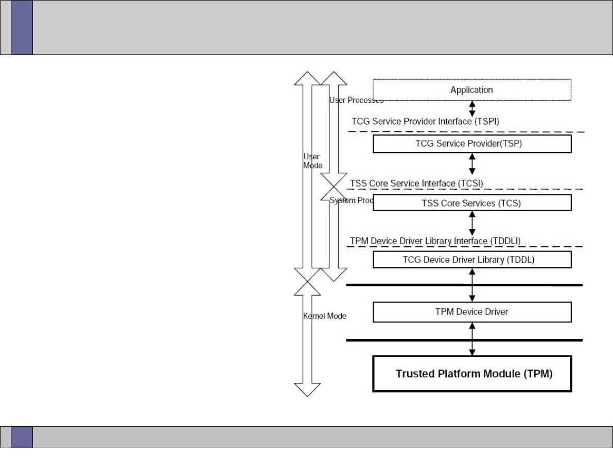
Trusted Computing Labs, IAIK TU Graz
4
●
TSS Service Provider (TSP)
–
top most module
–
standard API for applications
●
TSS Core Services (TCS)
–
service (single instance per
platform)
●
TSS Device Driver Library
(TDDL)
–
provides standard interface
●
TPM device driver
–
kernel mode
–
TPM vendor or TIS
●
TPM chip
TSS Highlevel Architecture
image © by TCG (TSS specification)
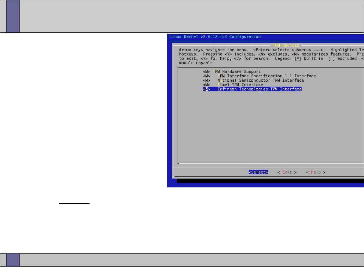
Trusted Computing Labs, IAIK TU Graz
5
TPM Access with Linux
●
Kernel drivers
–
TPM drivers included in
standard 2.6 kernels
–
vendor specific drivers
for 1.1 TPMs
●
included in the Kernel:
Infineon, Atmel, NatSemi
–
1.2 TPMs come with a
generic interface (TIS –
TPM Interface Specification)
–
Kernel includes TIS driver
that should work with all TIS compliant 1.2 TPMs
●
TPM is accessed as a character device via /dev/tpmX
●
very basic information is exported via SysFS (e.g. PCR contents)

Trusted Computing Labs, IAIK TU Graz
6
TPM Access with Windows
●
previous to Windows Vista:
–
vendor specific TPM device driver
–
vendor specific TDDL and some (vendor supplied) TSS on top of it
●
Windows Vista:
–
only supports 1.2 TPMs “out of the box”
–
likely is using a TIS driver (yet unconfirmed)
–
support for 1.1 TPMs (and maybe some 1.2 TPMs) has to be added
by the TPM manufacturer via a driver
–
Vista comes with a basic TPM abstraction layer called TPM Base
Services (TBS)
●
RPC based service only accessible from the local machine
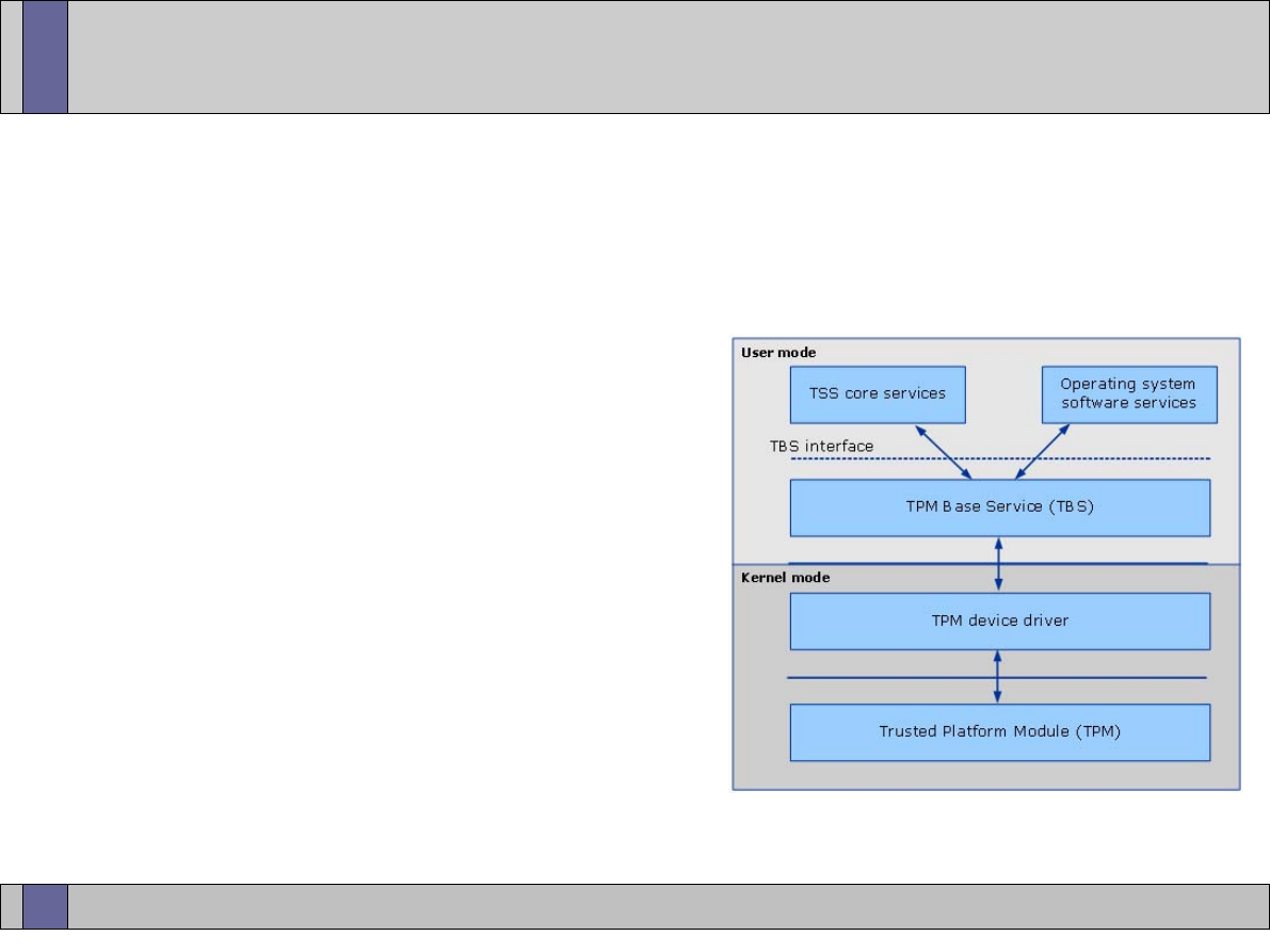
Trusted Computing Labs, IAIK TU Graz
7
Vista: TPM Base Service
●
TBS provides virtualization of TPM resources allowing multiple
applications (TSS, OS services, ...) access to the TPM
●
allows to restrict access to TPM commands on a “per command”
basis
●
resource virtualization:
–
key handles, auth handles, ... are re-
placed by virtual handles
–
TBS keeps mappings of handles
–
if TPM runs out of resources, TBS
takes care of swapping out entities
from the TPM
–
virtual resource handles are not
affected; if a swapped out resource
is used again (via its virtual resource
handle) the TBS tries to reload the entity into the TPM
image © by Microsoft (TBS specification)

Trusted Computing Labs, IAIK TU Graz
8
TDDL – TSS Device Driver Library
●
first TSS component running in user space
●
standardized interface such that every TSS using the TDDL
interface can communicate with the TPM regardless of the TPM
manufacturer
●
provides very simple abstraction layer for TPM access
–
open, close, transmit/receive
●
TDDL is single-threaded (command serialization has to be done in
upper layers)
●
interface between TDDL and device driver is vendor specific (at
least for non-TIS compliant TPMs)

Trusted Computing Labs, IAIK TU Graz
9
TCS – TSS Core Services
●
TCS is a service provider (daemon or system service)
●
one instance per system
●
in TCG design, the TCS is the only entity directly accessing the TPM
●
provides standardized functionality and a standard interface that is
accessed by the TSS Service Provider(s)
●
TCS is responsible for TPM command serialization
●
TCS builds the TPM command messages
●
management of TPM resources
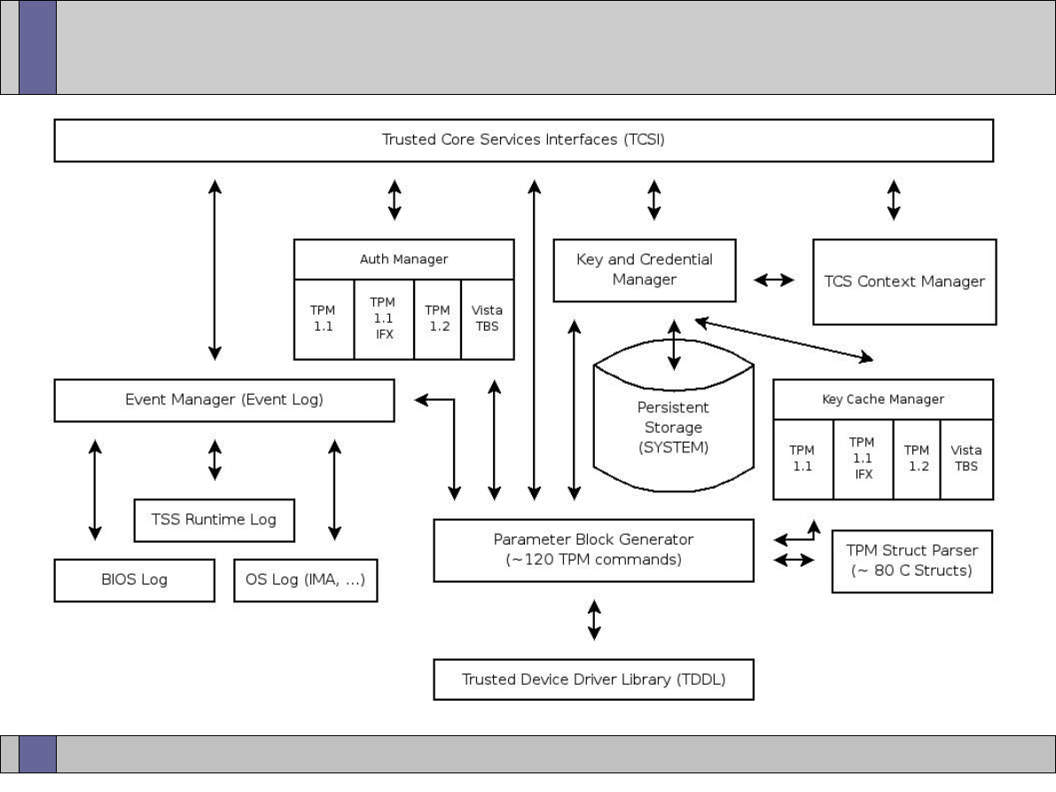
Trusted Computing Labs, IAIK TU Graz
10
TCS Architecture

Trusted Computing Labs, IAIK TU Graz
11
TCSI and TCS Context Management
●
TCS Interface (TCSI)
–
simple C style interface
–
each operation is intended to be atomic
–
allows multi-threaded access
–
TCSI can be accessed remotely (RPC or standardized SOAP interface)
●
all interaction with the TCS revolves around contexts
–
upper layers have to open a TCS context object before they can send
commands to the TCS
–
resources such as key handles or allocated memory belong to a
context
–
TCS contexts are managed by the TCS context manager

Trusted Computing Labs, IAIK TU Graz
12
TCS Parameter Block Generator
●
all commands actually send to the TPM pass through the PBG
●
converts TCS function calls into byte stream oriented TPM
command messages
●
parses TPM response byte streams
●
authorization data (via HMAC) and command validation is not done
in the TCS (typically done in TSP)

Trusted Computing Labs, IAIK TU Graz
13
Event Manager
●
together with extending PCRs, users can add log entries to the PCR
event log
–
main event log is managed by the TSS
●
events log entries are stored as TSS_PCR_EVENT entries
●
TCC_PCR_EVENT contains:
–
pcrIndex ... the PCR that was extended
–
pcrValue ... the value that was extended into the PCR
–
event
... description of the event
–
additional event log sources (not under control of TSS)
●
boot log (accessible via ACPI)
●
OS specific logs (IMA – Integrity Measurement Architecture for Linux;
Kernel extension that measures loaded kernel modules, executed
applications, ...)
●
The event log does not need to be stored in shielded locations
because tampering can be detected via the PCRs.
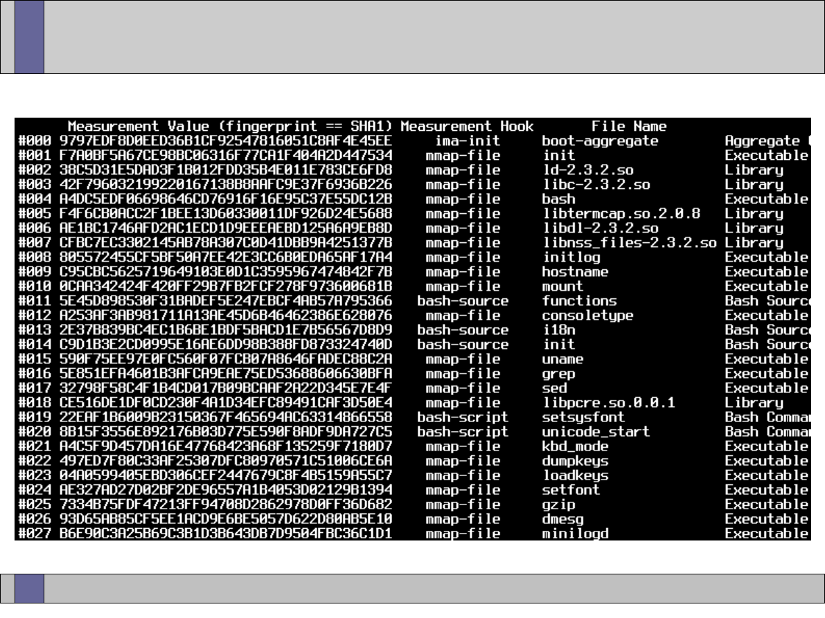
Trusted Computing Labs, IAIK TU Graz
14
Event Log Sample (IMA)

Trusted Computing Labs, IAIK TU Graz
15
Event Log Usage
●
event log can be transmitted (together with the signed PCR data
from TPM_Quote) to an external party (verifier)
●
from the TPM_Quote alone, the verifier might not be able to gain
sufficient knowledge about the system
–
the event log provides a much better insight on the systems state
–
but the event log on its own provides no evidence that it was not
manipulated
–
the way to verify the correctness of the event log is to replay the
individual events in software
●
start with a virtual (software) PCR of all zeros and extend the individual
PCR values from the event log into this PCR
●
compare the resulting virtual PCR with the actual PCR content contained
in the TPM_Quote
●
remember: the TPM_Quote was generated inside the TPM and is signed
●
if the virtual (expected) PCR contents matches the value contained in
TPM_Quote the provided event log can be assumed to be correct

Trusted Computing Labs, IAIK TU Graz
16
Key Management
●
TPM keys are created (and used) inside the TPM
●
keys inside the TPM do not survive power cycles (volatile memory)
●
to store such keys permanently, the TCS provides a persistent key
storage
●
keys managed by the TCS have to be assigned an identifier called
UUID (Universally Unique Identifier)
●
keys can be registered in persistent storage using this UUID
●
special keys such as the SRK have a predefined UUID
●
keys can be retrieved from the persistent storage using their UUID
●
remember: To load a key into the TPM, its parent key has to be
loaded previously. If the parent has not yet been loaded the TSS
returns an error.
●
keys remain in the persistent storage until the are unregistered

Trusted Computing Labs, IAIK TU Graz
17
Key Cache
●
loaded TPM keys are assigned a TPM keys handle
●
TPM key slots are limited – key swapping is required
–
not to be mistaken with TPM unloading/reloading!
–
when swapping in a swapped-out key, the parent key secret does
not have to be supplied (was already supplied when key was loaded)
–
swapped-out keys can only be loaded into the TPM of origin
–
swapped-out keys become invalid upon TPM power cycles
–
TPM 1.1:
●
optional command: TPM_SaveKeyContext / TPM_LoadKeyContext
●
TPM_EvictKey / TPM_LoadKey
problems: re-supply parent secret; changed PCRs for PCR bound keys
–
TPM 1.2:
●
mandatory command: TPM_SaveContext / TPM_LoadContext
●
TCS maps TPM key handles to (stable) TCS key handles

Trusted Computing Labs, IAIK TU Graz
18
Authorization Manager
●
auth sessions (OIAP, OSAP) are referenced by TPM auth handles
●
number of concurrently active auth sessions is limited
●
auth session swapping is required
–
swapped-out auth sessions can only be loaded into the TPM of origin
–
swapped-out auth sessions become invalid upon TPM power cycles
–
TPM 1.1
●
optional command: TPM_SaveAuthContext / TPM_LoadAuthContext
only alternative: auth session termination
–
TPM 1.2
●
TPM_SaveContext / TPM_LoadContext
●
auth handles change when auth handles get re-loaded -> TCS has
to maintain stability for upper layers

Trusted Computing Labs, IAIK TU Graz
19
TSP – TSS Service Provider
●
shared library linked to applications that require TPM access
–
application developers do not need to have in depth TPM knowledge
–
multiple instances per platform (in contrast to single-instance TCS)
●
not only provides TPM access (via TCS) but also includes additional
convenience functionality like signature verification
●
TPM command authorization and validation (initiating authorization
sessions, ...)
●
access to remote TCS via vendor specific mechanisms (RPC) or via
standardized SOAP messages
●
persistent user storage: persistent key store similar to persistent
system storage provided by TCS but individual for every user
●
provides a standardized C interface (TSPI)
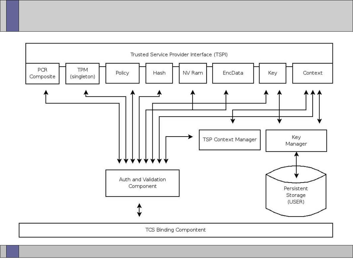
Trusted Computing Labs, IAIK TU Graz
20
TSP Architecture
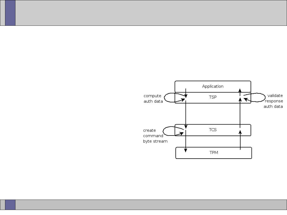
Trusted Computing Labs, IAIK TU Graz
21
TPM Command Authorization
●
For authorized entities, the TSP computes the authorization data.
remember: authData is HMAC over parts of the input parameters,
nonceEven, nonceOdd and contAuthSession; HMAC key is the
entity secret (e.g. key usage secret)
●
The command, together with
the authData, is sent to the
TCS. The PBG builds the
command message and sends
it to the TPM.
●
Result message is sent to the
TSP where the response is
validated.
again: HMAC over parts of the
result, nonceEven, nonceOdd
and contAuthSession; HMAC key is the entity secret.

Trusted Computing Labs, IAIK TU Graz
22
TSP Context Object
●
context object is the main entry point when interacting with the
TPM
●
holds basic information about environment configuration
●
connection establishment to TCS
●
allows access to the default policy
●
provides memory management mechanisms (FreeMemory)
●
allows to query the capabilities of the TCS implementation
●
central point for registering and retrieving keys from the TSSs
persistent storage (RegisterKey, LoadKeyByUUID, UnregisterKey)
●
used to create all other TSP objects
–
TPM, Policy, Key, Hash, EncData, PcrComposite, NvRam
–
TSP objects are configured via init flags

Trusted Computing Labs, IAIK TU Graz
23
Context – Java Code Samples
// create a context object
TcIContext context
=
new
TcTssJniFactory
().
newContextObject
();
// connect to TCS (null = localhost:30003)
context
.
connect
(
null
);
// create other TSP objects
TcIRsaKey key
=
context
.
createRsaKeyObject
(...);
// init flags for key type, ...
TcIHash hash
=
context
.
createHashObject
(
TcTssDefines
.
TSS_HASH_SHA1
);
TcIPcrComposite pcrComp
=
context
.
createPcrCompositeObject
(
0
);
// no init flags
// ...
// register key in system storage (parent SRK)
context
.
registerKey
(
key
,
TcTssDefines
.
TSS_PS_TYPE_SYSTEM
,
uuidKey
,
TcTssDefines
.
TSS_PS_TYPE_SYSTEM
,
TcUuidFactory
.
getInstance
().
getUuidSRK
());
// load key with given UUID from system storage
context
.
loadKeyByUuidFromSystem
(
uuidKey
);

Trusted Computing Labs, IAIK TU Graz
24
TSP Policy Object
●
TPM entities such as keys or encrypted data require the knowledge
of a usage secret
●
at TSP level, these secrets are managed by the Policy object
●
secrets can have a limited lifetime or a usage count
●
one policy object can be assigned to multiple TSP objects
–
therefore all those objects use the same secret
–
changing the policy secret affects all assigned TSP objects
●
the context object holds a default policy object
–
all new objects are assigned to this default policy upon creation
–
to set an individual secret for an object, create a new policy object
and assign this policy to the object
–
remember: changing the secret of a policy affects all assigned
objects!

Trusted Computing Labs, IAIK TU Graz
25
TSP Policy Object
●
one exception: the TPM object is not assigned to the default policy
upon creation but has an own policy
●
default policy can be accessed via the GetDefaultPolicy method of
the context
●
policies of other authorized objects (keys, encData, ...) can be
accessed via the GetPolicyObject function
●
secrets of authorized objects can be changed using the
ChangeAuth method

Trusted Computing Labs, IAIK TU Graz
26
Policy – Java Code Samples
// create usage policy object
TcIPolicy usgPolicy
=
context
.
createPolicyObject
(
TcTssDefines
.
TSS_POLICY_USAGE
);
// set password string
TcBlobData secret
=
TcTssStructFactory
.
newBlobData
().
initString
(
"myBigSecret"
);
usgPolicy
.
setSecret
(
TcTssDefines
.
TSS_SECRET_MODE_PLAIN
,
secret
);
// assign policy object to authorized entity (key)
usgPolicy
.
assignToObject
(
key
);
// do something with the key
// ...
// (optionally) flush secret
usgPolicy
.
flushSecret
();
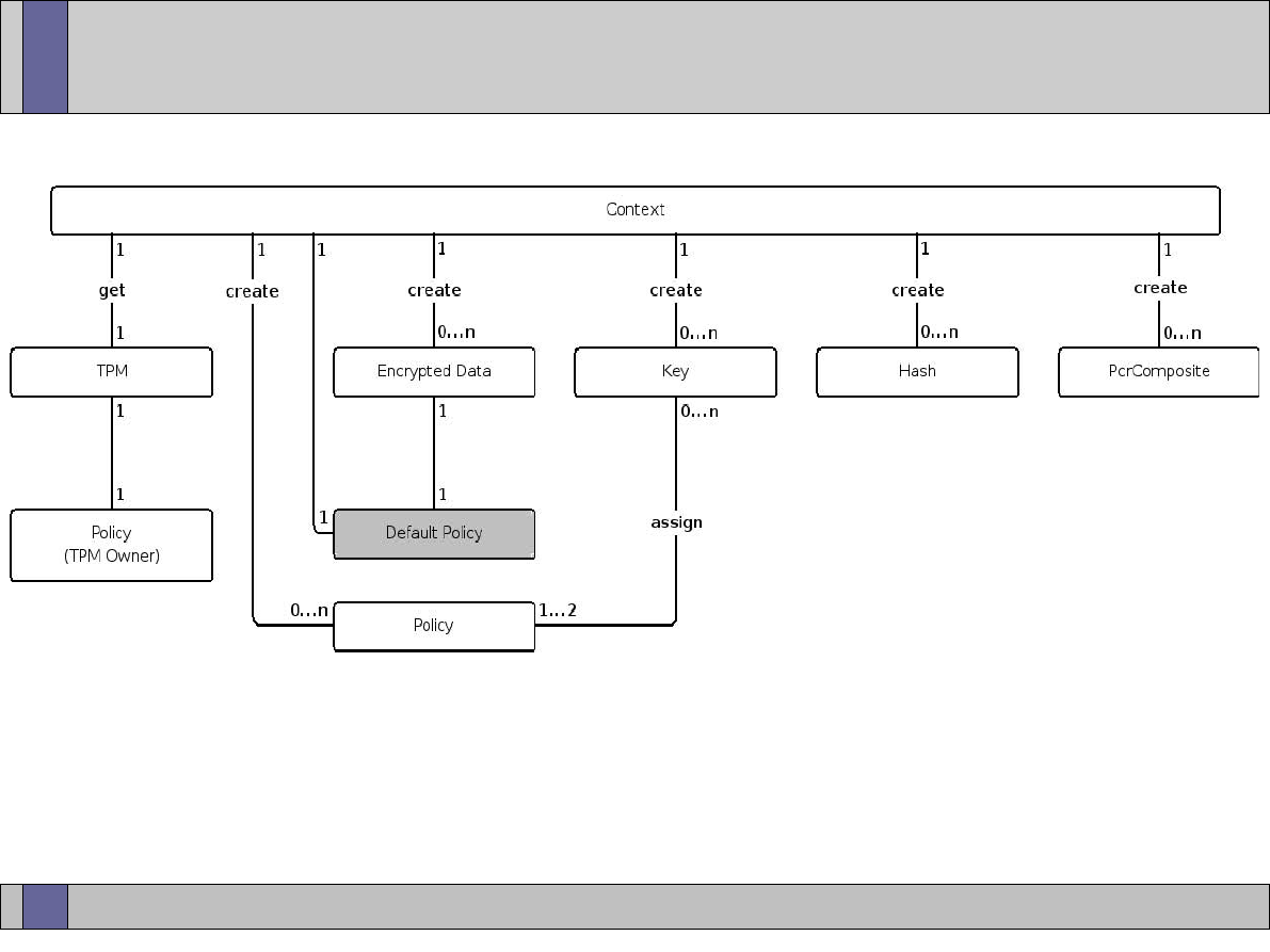
Trusted Computing Labs, IAIK TU Graz
27
TSP Object Relationships
●
TSP objects are created via the context object
●
authorized objects are, by default, assigned to the default upon
creation

Trusted Computing Labs, IAIK TU Graz
28
TSP TPM Object
●
provides access to administrative TPM functions like
–
TakeOwnership/ClearOwnership
–
CollateIdentity/ActivateIdentity for AIK creation
–
querying TPM capabilities and manipulating TPM status
●
TPM version and manufacturer
●
number of PCRs provided by the TPM
●
...
–
getting random numbers from the TPMs hardware RNG
–
PCR access (PcrExtend/PcrRead), event log access
–
Quote operation for attestation
●
TPM object is assigned to one specific policy object (owner policy)
●
implemented as singleton
●
represents the owner of the TPM

Trusted Computing Labs, IAIK TU Graz
29
TPM – Java Code Samples
// get TPM object
TcITpm tpm
=
context
.
getTpm
();
// read TPM capability (number of PCRs)
TcBlobData subCap
=
TcTssStructFactory
.
newBlobData
().
initUINT32
((
int
)
TcTssDefines
.
TSS_TPMCAP_PROP_PCR
);
tpm
.
getCapability
(
TcTssDefines
.
TSS_TPMCAP_PROPERTY
,
subCap
);
// get 128 bytes of random data
TcBlobData randomData
=
tpm
.
getRandom
(
128
);
// extend PCR 10 (without adding an event log entry)
TcBlobData data
=
TcTssStructFactory
.
newBlobData
().
initString
(
"some arbitrary data"
);
tpm
.
pcrExtend
(
10
,
data
.
sha1
(),
null
);
// read contents of PCR 10
TcBlobData pcrValue
=
tpm
.
pcrRead
(
10
);

Trusted Computing Labs, IAIK TU Graz
30
TSP Key Object
●
TSP level representation of TPM keys
●
assigned to policy objects handling key usage or migration secrets
●
provides functionality to
–
create new TPM protected keys
●
key type and parameters are passed via a set of init flags
–
load/unload keys into/from TPM
–
certify TPM keys: provide evidence that a key actually is a TPM
protected key
–
access to the raw TPM key blob (public key and parent-protected
private key) via GetAttribData/SetAttribData functions

Trusted Computing Labs, IAIK TU Graz
31
Key - Java Code Samples
// setup storage key
TcIRsaKey storageKey
=
context_
.
createRsaKeyObject
(
TcTssDefines
.
TSS_KEY_TYPE_STORAGE
|
TcTssDefines
.
TSS_KEY_SIZE_2048
|
TcTssDefines
.
TSS_KEY_NOT_MIGRATABLE
);
storeKeyUsgPolicy_
.
assignToObject
(
storageKey
);
storeKeyMigPolicy_
.
assignToObject
(
storageKey
);
// create and load storage key
storageKey
.
createKey
(
srk_
,
null
);
storageKey
.
loadKey
(
srk_
);
// setup signing key
TcIRsaKey certifyKey
=
context_
.
createRsaKeyObject
(
TcTssDefines
.
TSS_KEY_SIZE_2048
|
TcTssDefines
.
TSS_KEY_TYPE_SIGNING
);
signKeyUsgPolicy_
.
assignToObject
(
certifyKey
);
signKeyMigPolicy_
.
assignToObject
(
certifyKey
);
// create and load signing key
certifyKey
.
createKey
(
srk_
,
null
);
certifyKey
.
loadKey
(
srk_
);
// certify storage key using signing key
TcTssValidation validation
=
storageKey
.
certifyKey
(
certifyKey
,
null
);
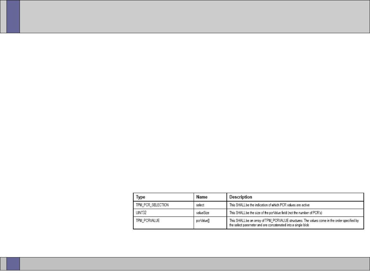
Trusted Computing Labs, IAIK TU Graz
32
TSP PcrComposite Object
●
TSP level object that allows to define a set of PCR values
●
used to specify PCRs for e.g. CreateKey, Seal, ...
●
SetPcrValue/GetPcrValue
–
PCR index, PCR value (can be current or “future” pcr value)
–
allows to set multiple PCRs (therefore “composite”)
●
SelectPcr
–
used when not the PCR values are of interest but only the PCR
indices (e.g. select set of PCRs for TPM Quote)
●
GetCompositeHash
–
returns hash of
PCR_COMPOSITE
structure
–
composite hash is what is returned by TPM_Quote
TPM_PCR_COMPOSITE
upper image © by TCG (TPM specification)

Trusted Computing Labs, IAIK TU Graz
33
TSP EncData Object
●
TSP object for data encryption; 2 types: with or without PCRs
●
without PCRs: Bind/Unbind
–
Bind: encrypt the given data blob using the public part of the key
–
Bind is a pure software (TSS) operation
–
Unbind requires the private key and therefore happens in the TPM
–
migratable vs. non-migratable binding keys
●
with PCRs: Seal/Unseal
–
Seal: includes specified set of PCRs in encryption process
–
UnSeal: only releases the decrypted data if the specified set of PCRs
matches the current PCR state
–
Seal/Unseal only works with non-migratable keys
●
plain/encrypted data are set/retrieved using Get/SetAttribData
●
input data length is limited by key size (TSS does no data blocking)

Trusted Computing Labs, IAIK TU Graz
34
Bind/Unbind Java Code Samples
// create new binding key
TcIRsaKey key
=
context_
.
createRsaKeyObject
(
TcTssDefines
.
TSS_KEY_TYPE_BIND
|
TcTssDefines
.
TSS_KEY_SIZE_2048
|
TcTssDefines
.
TSS_KEY_NOT_MIGRATABLE
);
keyUsgPolicy_
.
assignToObject
(
key
);
keyMigPolicy_
.
assignToObject
(
key
);
key
.
createKey
(
srk_
,
null
);
key
.
loadKey
(
srk_
);
// create encrypted data object
TcIEncData encData
=
context_
.
createEncDataObject
(
TcTssDefines
.
TSS_ENCDATA_BIND
);
// bind data
TcBlobData rawData
=
TcTssStructFactory
.
newBlobData
().
initString
(
"Hello World!"
);
encData
.
bind
(
key
,
rawData
);
// get bound data
TcBlobData boundData
=
encData
.
getAttribData
(
TcTssDefines
.
TSS_TSPATTRIB_ENCDATA_BLOB
,
TcTssDefines
.
TSS_TSPATTRIB_ENCDATABLOB_BLOB
);
// unbind
TcBlobData unboundData
=
encData
.
unbind
(
key
);

Trusted Computing Labs, IAIK TU Graz
35
Seal/Unseal Java Code Samples
// create new key
TcIRsaKey key
=
context_
.
createRsaKeyObject
(
TcTssDefines
.
TSS_KEY_TYPE_STORAGE
|
TcTssDefines
.
TSS_KEY_SIZE_2048
);
keyUsgPolicy_
.
assignToObject
(
key
);
keyMigPolicy_
.
assignToObject
(
key
);
key
.
createKey
(
srk_
,
null
);
key
.
loadKey
(
srk_
);
// create sealed data object
TcIEncData encData
=
context_
.
createEncDataObject
(
TcTssDefines
.
TSS_ENCDATA_SEAL
);
// set a secret for the sealed data
TcIPolicy encDataPolicy
=
context
.
createPolicyObject
(
TcTssDefines
.
TSS_POLICY_USAGE
);
TcBlobData encDataSecret
=
TcTssStructFactory
.
newBlobData
().
initString
(
"data secret"
);
encDataPolicy
.
setSecret
(
TcTssDefines
.
TSS_SECRET_MODE_PLAIN
,
encDataSecret
);
encDataPolicy
.
assignToObject
(
encData
);
// get PCR value of PCR 8
TcBlobData pcrValue
=
context_
.
getTpm
().
pcrRead
(
8
);
// create PCR composite
TcIPcrComposite pcrs
=
context_
.
createPcrCompositeObject
(
0
);
pcrs
.
setPcrValue
(
8
,
pcrValue
);
// seal to current value of PCR 8
TcBlobData rawData
=
TcTssStructFactory
.
newBlobData
().
initString
(
"Hello World!"
);
encData
.
seal
(
key
,
rawData
,
pcrs
);
// get sealed data
TcBlobData sealedData
=
encData
.
getAttribData
(
TcTssDefines
.
TSS_TSPATTRIB_ENCDATA_BLOB
,
TcTssDefines
.
TSS_TSPATTRIB_ENCDATABLOB_BLOB
);
// unseal
TcBlobData unsealedData
=
encData
.
unseal
(
key
);

Trusted Computing Labs, IAIK TU Graz
36
TSP Hash Object
●
TSP level hash object that allows to compute hash values of given
data which can then be signed using TPM keys
●
UpdateHashValue
–
updates the hash value with the provided data
●
Set/GetHashValue
–
allows setting/retrieving the hash value represented by the object
●
HashSign
–
signs the hash value held by the object using the provided TPM key
–
encryption with the private key inside the TPM
●
VerifySignature
–
verifies the provided signature blob using the provided key
–
decrypts the signature blob using pub key and compares the result
to the expected hash value provided via Set/GetHashValue
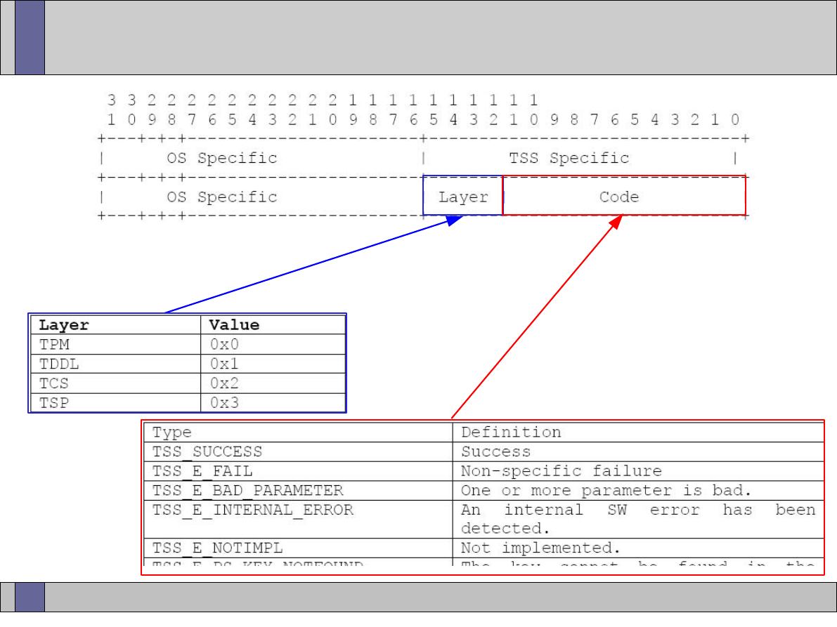
Trusted Computing Labs, IAIK TU Graz
37
TSS return codes

Trusted Computing Labs, IAIK TU Graz
39
Finally – Coming to an end
Questions?
Thank you very much
for your attention!

Trusted Computing Labs, IAIK TU Graz
40
Open_TC EC Contract No: IST-027635
●
The Open_TC project is co-financed by the EC.
contract no: IST-027635
●
If you need further information, please visit our
website www.opentc.net or contact the coordinator:
Technikon Forschungs- und Planungsgesellschaft mbH
Richard-Wagner-Strasse 7, 9500 Villach, AUSTRIA
Tel. +43 4242 23355 0
Fax. +43 4242 23355 77
Email coordination@opentc.net
The information in this document is provided “as is”, and no guarantee or
warranty is given that the information is fit for any particular purpose.
The user thereof uses the information at its sole risk and liability.

Trusted Computing Labs, IAIK TU Graz
1
Trusted Computing
Infrastructure
Martin Pirker <martin.pirker@iaik.tugraz.at>
v20070327

Trusted Computing Labs, IAIK TU Graz
2
Review
●
TPM: dedicated hardware module, fixed to mainboard
●
offers common level of cryptographic operations
●
TSS: standardized software layer
●
EK – unique key per TPM
●
AIK – derived identity keys
●
stand-alone trusted platforms.... not very interesting
●
trusted interactions over network -> infrastructure needed
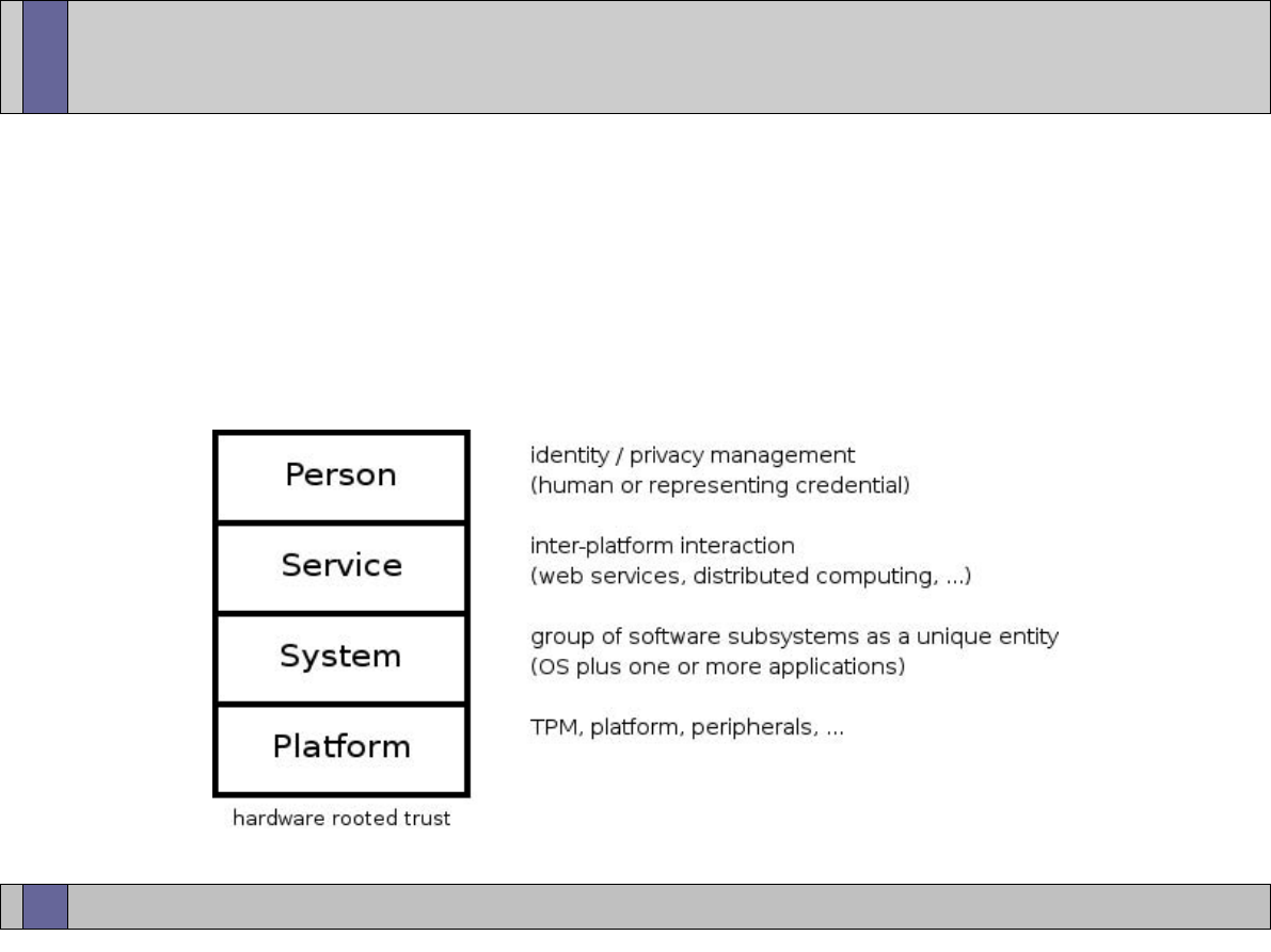
Trusted Computing Labs, IAIK TU Graz
3
Infrastructure
●
"set of entities, functions and roles that are needed to support
the use of Trusted Platforms throughout their lifecycle"
●
layers of abstraction / independent speakers of assertions

Trusted Computing Labs, IAIK TU Graz
4
Infrastructure
●
framework
–
TPM
–
TSS
–
PTS (platform trust services)
●
capture / measure runtime integrity information
●
PCR event log, future: XML reports of system (components)
–
certification authorities specific to Trusted Computing (Privacy CA)
–
classic CA service (SKAE)
–
backup / migration services
–
trusted network connect
●
e.g. TLS plus TC attestation

Trusted Computing Labs, IAIK TU Graz
5
Trusted Platform Life Cycle
●
preparation / provisioning
–
TPM chip manufacturing
–
Trusted Building Blocks (TBB) manufacturing
–
platform manufacturing
–
assembly of components
–
TPM chip identity imprinting
●
EK generation
–
specifications compliance testing (external lab)
●
certification of components

Trusted Computing Labs, IAIK TU Graz
6
Trusted Platform Life Cycle
●
deployment / usage
–
integrity values creation
●
serial number, ...
–
integrity values collection
●
file, CD, website, ...
–
deployment scenario specific customizing
–
take platform ownership
–
user partitions
–
key(s) generation
–
interaction with certification authorities on network
●
credentials creation / publication
–
...daily operation

Trusted Computing Labs, IAIK TU Graz
7
Trusted Platform Life Cycle
●
retirement / redeployment
–
key migration
–
key backup
–
key archival
–
key erasure
–
revocation of active credentials / identities
–
clear ownership
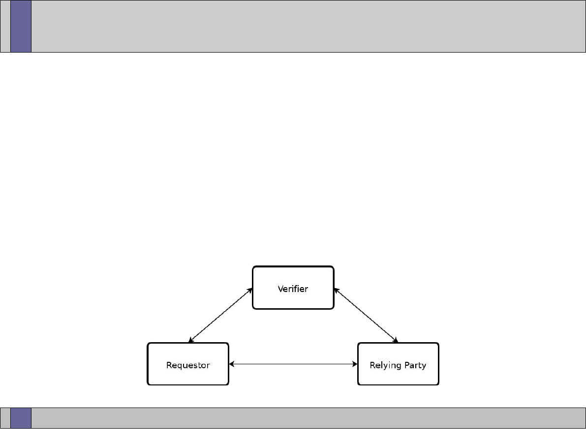
Trusted Computing Labs, IAIK TU Graz
8
Authentication Model
●
classic example of trust relationships
–
bank (Verifier) issues credit card (credential) to user (Requestor).
–
user (Requestor) wants to do shopping at merchant (Relying Party)
–
merchant (Relying Party) verifies credit card (credential) at bank
(Verifier) before communicating further with user (Requestor)
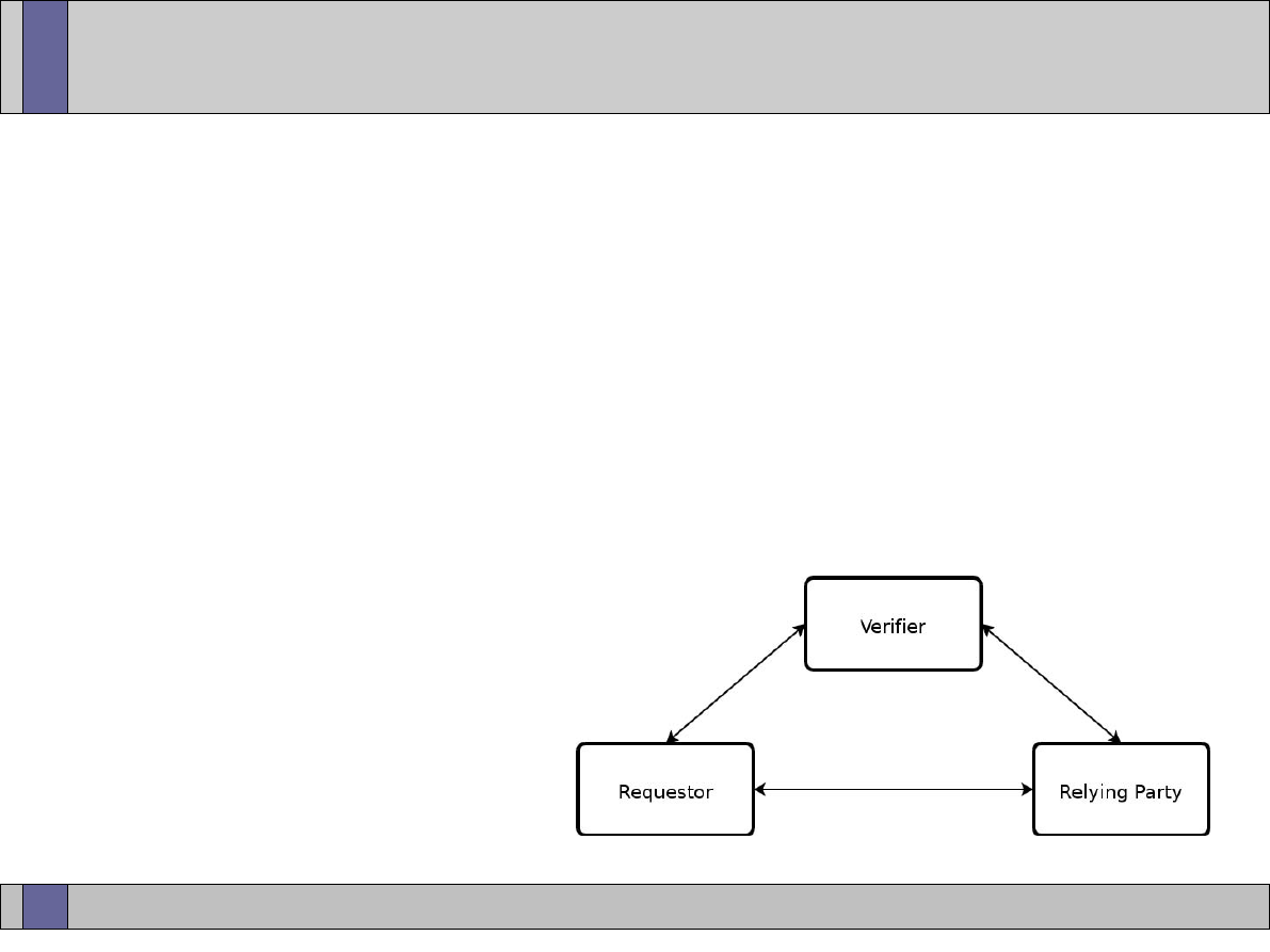
Trusted Computing Labs, IAIK TU Graz
9
Authentication Model
●
Relying Party
–
offers “some” service
–
only to specific set of “trusted” clients
–
depends on Verifier to distinguish (in)valid requests
●
Requestor (User)
–
wants to do transaction with a Relying Party
–
possesses Trusted Hardware capabilities
–
claims trustworthiness

Trusted Computing Labs, IAIK TU Graz
10
Authentication Model
●
Verifier
–
mediates between Requestor and Relying Party
–
Relying Party depends on Verifier to evaluate claims and assertions
presented by Requestor
–
all three parties must understand the same criteria (in syntax and
semantic!) in order to come to meaningful evaluation results
according to commonly agreed policies
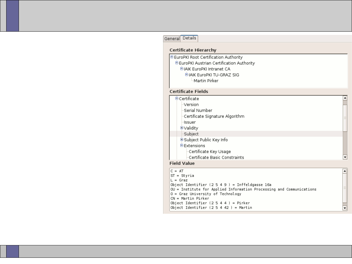
Trusted Computing Labs, IAIK TU Graz
11
Credential
●
(X509) certificate
–
one possible manifestation
of security credential
–
basically a blob of data
–
issuer
–
subject
–
public key
–
validity period
–
intended purpose
–
additional custom
information / extensions
–
digital signature of issuer
●
“I vouch for the correctness of the included information”

Trusted Computing Labs, IAIK TU Graz
12
TC Certificates
●
certificate types and extensions specific for Trusted Computing
●
used in the TCG TC model
–
TPM endorsement key (EK) credential
–
Platform Endorsement (PE) credential
–
Attested Identity Key (AIK) credential
–
Subject Key Attestation Evidence (SKAE) certificate extension
–
TPM 1.1 spec (no longer of interest?)
●
Conformance credential
●
Validation credential

Trusted Computing Labs, IAIK TU Graz
13
TPM endorsement key (EK) credential
●
“TCPA Trusted Platform Module Endorsement”
●
binding of public endorsement key to a particular TPM chip
●
asserts that the holder of the private endorsement key is a TPM
conforming to TCG specifications
●
asserts correct implementation of protection capabilities,
shielded locations etc.
●
description of
–
TPM manufacturer (e.g. “Infineon”)
–
TPM model (e.g. “SLB9635TT1.2”)
–
TPM version (e.g. “1.2”)
●
description of
–
evaluation criteria (FIPS, CommonCriteria, ISO9000, ...)

Trusted Computing Labs, IAIK TU Graz
14
TPM endorsement key (EK) credential
●
description of
–
manufacturing and initialization conditions
●
EK generation internal vs. injected
●
by manufacturer or at platform assembly
●
typical issuer is manufacturer or entity who creates + inserts EK
–
TPMs on market today typically come initialized with endorsement
key pair, but without certificate :-(
–
all Infineon 1.1+1.2 TPMs ship preloaded with EK certificates in
on-chip NVRAM
●
typical user of EK certificate
–
Privacy CA (see later slides)
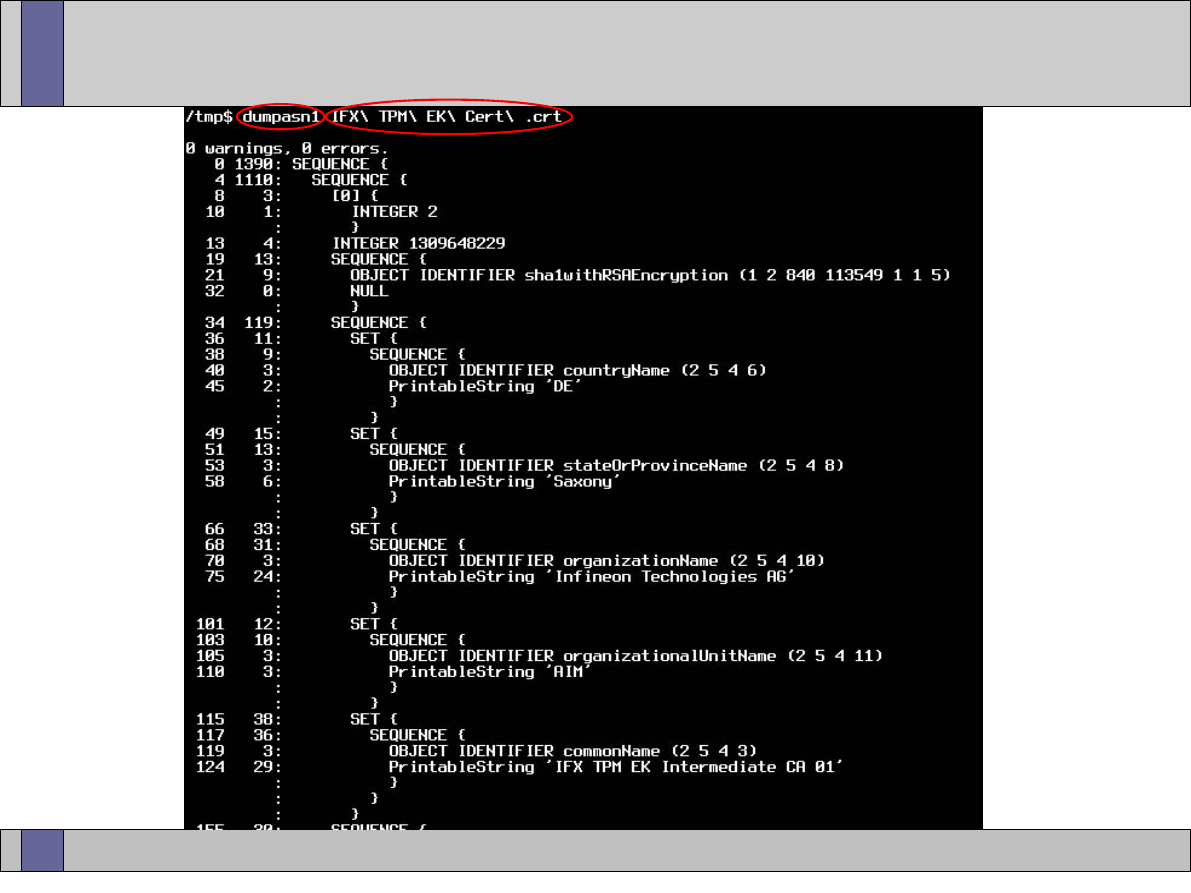
Trusted Computing Labs, IAIK TU Graz
15
IFX EK credential ASN1 dump
SERIAL
ISSUER
<- from http://www.infineon.com/TPM/certificate/
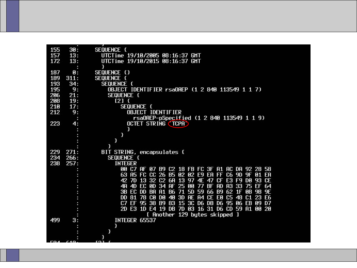
Trusted Computing Labs, IAIK TU Graz
16
IFX EK credential ASN1 dump
VALIDITY
TPM PUBLIC EK
KEY PARAMS
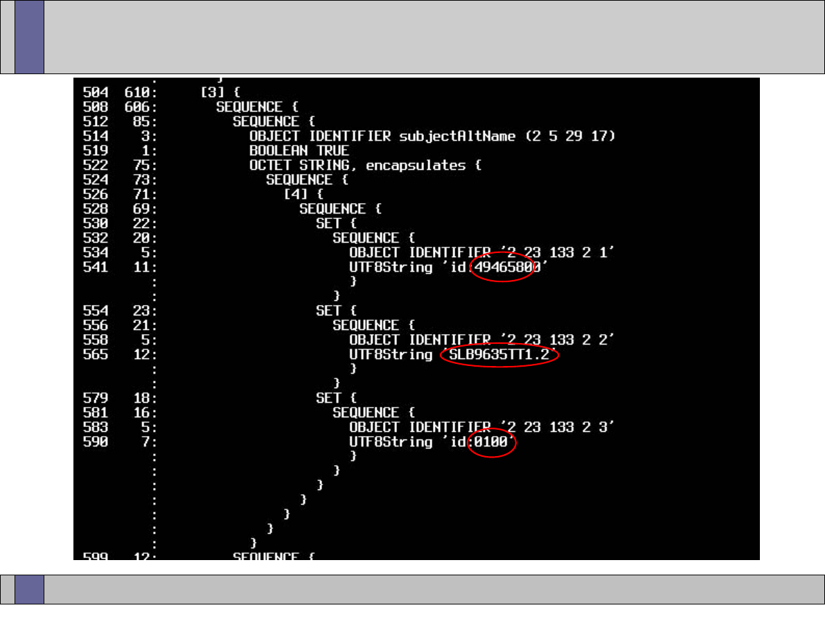
Trusted Computing Labs, IAIK TU Graz
17
IFX EK credential ASN1 dump
IFX
MANUFACTURER
MODEL
VERSION
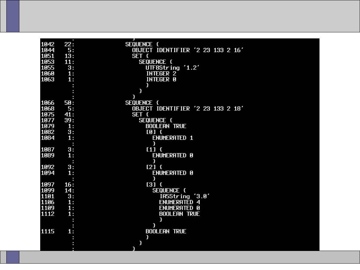
Trusted Computing Labs, IAIK TU Graz
18
IFX EK credential ASN1 dump
TPM spec
FAMILY
LEVEL
REVISION
tpmSecurityAssertions
fieldUpgradable
EKGeneration = injected
EKGen.Location = tpmManufacturer
EKCertGen.Loc. = tpmManufacturer
CommonCriteriaMeasures
EvaluationAssuranceLevel
EvaluationStatus = designedToMeet

Trusted Computing Labs, IAIK TU Graz
19
Platform Endorsement (PE) credential
●
“TCPA Trusted Platform Endorsement”
●
attests that a specific platform contains a unique TPM and
Trusted Building Blocks (TBB)
●
reference to EK credential of TPM contained in platform
●
description of
–
platform manufacturer
–
platform model
–
platform version
●
description of
–
evaluation criteria (FIPS, CommonCriteria, ISO9000, ...)
●
typical issuer is the platform manufacturer (e.g. OEM)
●
never seen one in real life

Trusted Computing Labs, IAIK TU Graz
20
Review
●
Endorsement Key
–
uniquely identifies TPM
●
and unfortunately allows potential tracking of the platforms users
–
remains unchanged over the lifetime of the TPM hardware module
–
can only be used for
●
taking ownership
●
creation of “identity” keys
●
Attestation Identity Key (AIK)
–
keypair created within TPM, not migratable
–
no direct relationship to EK

Trusted Computing Labs, IAIK TU Graz
21
Attested Identity Key (AIK) cred.
●
Attestation Identity Key (AIK)
–
can be attested with EK +“Privacy CA” that it originated in a TPM
–
a user can create “infinite” AIKs
–
use different AIKs for different services
–
better privacy protection
●
Attestation Identity Credential
–
“TCPA Trusted Platform Identity”
–
reference to EK credential of TPM contained in platform
–
reference to PE credential of platform
–
user chosen label for later identification
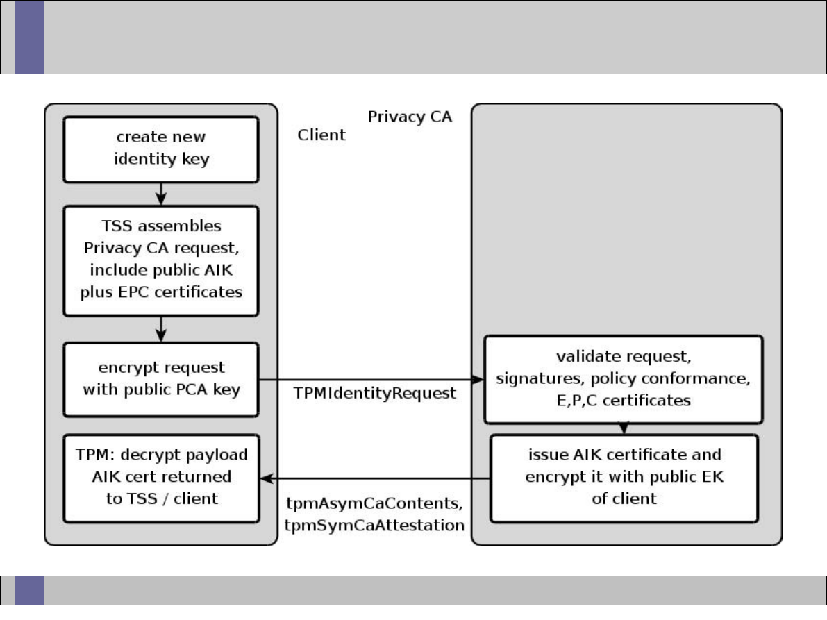
Trusted Computing Labs, IAIK TU Graz
22
AIK cycle

Trusted Computing Labs, IAIK TU Graz
23
Privacy CA request
●
TpmIdentityRequest from user/client to Privacy CA/server
–
version: currently only one version
–
asymAlg: identifier of asymmetric cipher algorithm (usually RSA)
–
asymBlob: binary blob containing symmetric session key,
encrypted with Privacy CA public key
–
symAlg: identifier of symmetric cipher (usually AES)
–
symBlob: actual request payload, encrypted with symmetric key
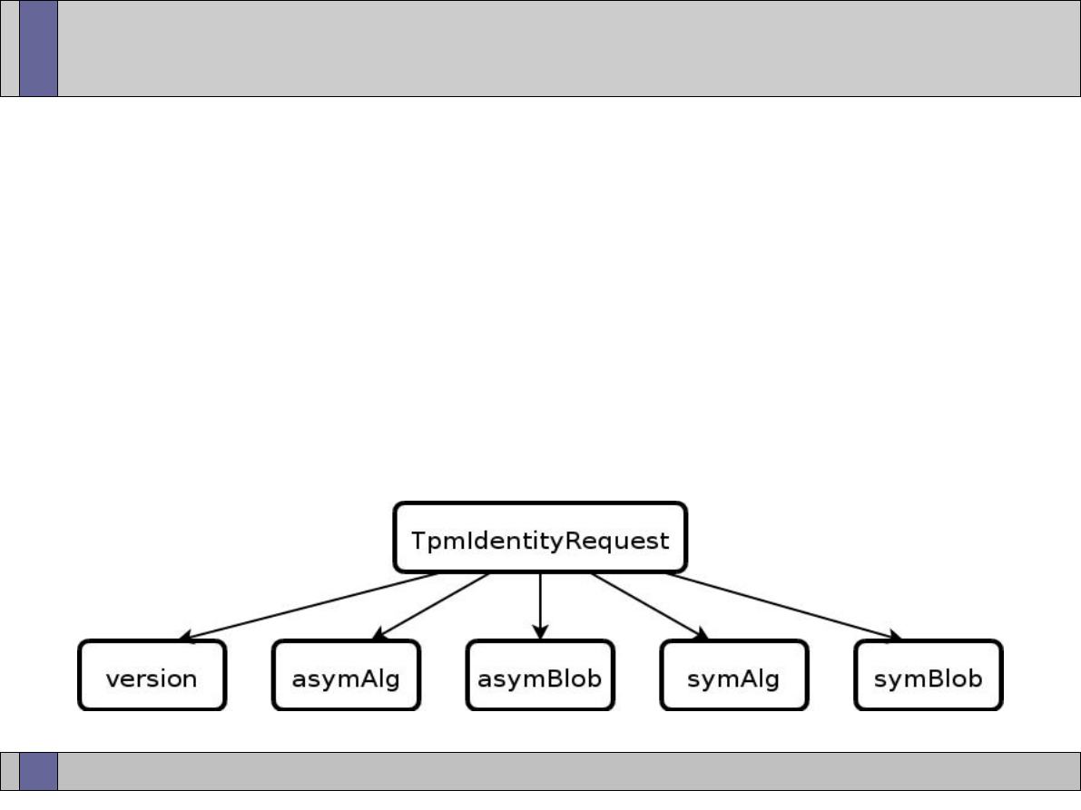
Trusted Computing Labs, IAIK TU Graz
24
Privacy CA request
●
discussion
–
asym vs. sym encryption
●
AES (symmetric) = fast
●
RSA (asymmetric) = slow
–
client needs to know public key of Privacy CA
●
received as part of a certificate?
–
request encrypted, no man-in-the-middle problem
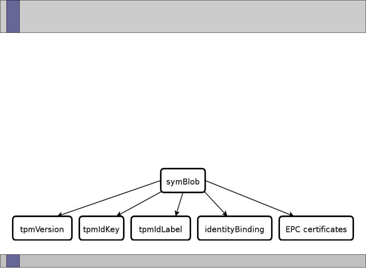
Trusted Computing Labs, IAIK TU Graz
25
Privacy CA request
●
contents of encrypted identity proof
–
tpmVersion: major/minor version of TPM
–
tpmIdKey: public part of AIK key
–
tpmIdLabel: requested label for AIK certificate
–
identityBinding: result of signature with AIK private key over
structure (... ,label , public key, version, ...)
–
EPC certificates: copies of TPM endorsement, platform and
conformance certificate

Trusted Computing Labs, IAIK TU Graz
26
Privacy CA request
●
discussion
–
client requests binding of specific public key to self chosen label
–
includes proof for compliant TPM / platform
–
includes proof of private key possession

Trusted Computing Labs, IAIK TU Graz
27
Privacy CA
●
processing of client request
–
decrypt request
–
validate identityBinding Signature
●
recreate expected structure, compare with request content
–
validation of credentials
●
endorsement
–
currently only certificate chains from Infineon publicly available
●
platform
●
conformance
–
check if request conforms to published Privacy CA policy
●
restrictions to specific client base?
●
restrictions on amount of AIKs per TPM?
●
....
–
issue AIK certificate

Trusted Computing Labs, IAIK TU Graz
28
Privacy CA response
●
contents of encrypted PrivacyCA response blobs
–
tpmAsymCaContents encrypted with public EK of TPM
–
decryption by TPM reveals
●
idDigest = hash over public key structure of AIK
●
sessionKey for symmetric cipher
–
session key decrypts encrypted AIK certificate (encCredential)
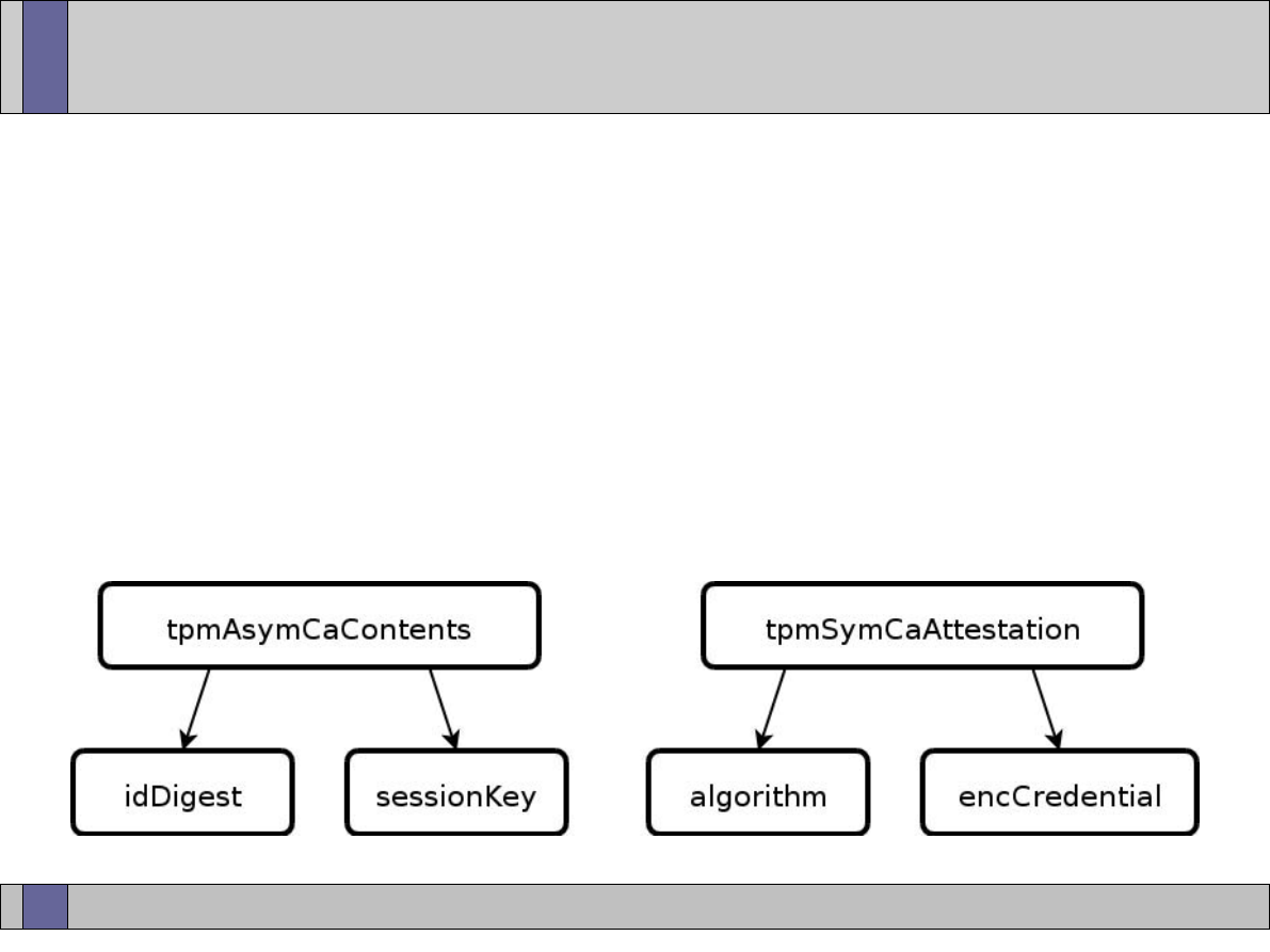
Trusted Computing Labs, IAIK TU Graz
29
Privacy CA response
●
discussion
–
response encrypted, no man-in-the-middle problem
–
encryption with public EK specifies distinct receiver
●
validation of EK credential confirms TPM hardware (no emulator)
–
the PCA does not know if the AIK certificate in the response is
actually ever “activated” at client side

Trusted Computing Labs, IAIK TU Graz
30
Privacy CA
●
Privacy CA as “anonymizer”
–
converts “real” identity embodied by EK credential into “derived”
identity of AIK certificate
–
is the only entity knowing the link EK <--> AIK
–
do you / we trust a Privacy CA service?
●
why do you trust the root certificates preloaded in your webbrowser?
–
mode of PCA operation is decision between protection of customers
and self protection
●
different vendors, different privacy commitments?
●
more money = more privacy? :-(
●
market will decide?
–
need for publication of Privacy CA policy
–
encoding of PCA policy in AIK certificate for automated processing

Trusted Computing Labs, IAIK TU Graz
31
Privacy CA modes
●
“forget everything of request after issuance of AIK certificate”
–
pro
●
maximum privacy, no later EK <--> AIK linking possible
●
still allows later verification of signature on AIK certificate by PCA
–
“this is my signature, it is correct and back then when I issued the
certificate everything was surely ok”
–
con
●
opens PCA service for abuse
●
no records on how many certificates are already issued for specific TPM
●
no records on issued labels, “all” certificates can have same label
●
denial of service
–
flood PCA with requests
–
PCA must honour every valid looking request because it cannot link
one request to the other

Trusted Computing Labs, IAIK TU Graz
32
Privacy CA modes
●
“remember data of request”
–
pro
●
allows internal(!) enforcement of PCA policies
–
maximum number of active AIKs per EK
–
only distinct labels per EK
–
active / revoked credentials list per EK
●
allows detection of denial of service abuse
–
why would someone want 100 new AIK certificates per second
for one EK...
–
con
●
link EK <--> AIK can be traced back
●
potentially large database storage for history required
–
e.g. client wants maximum privacy and thus a fresh AIK for every
new transaction
●
compromise of PCA database

Trusted Computing Labs, IAIK TU Graz
33
Privacy CA
●
open issues
–
AIK cycle request / response are binary blobs
●
compatibility among different TSS implementations unknown
●
specifications mention ASN1 / DER encoding
–
but nobody is doing it (yet)
–
no infrastructure protocol standardized in specifications
●
only suggestions to enhance / extend deployed ones
●
Privacy CA cycle currently “one blob to server, get 2 blobs back”
●
how to map / merge other TC PKI operations into existing infrastructure
–
Privacy CA concept depends on trust of Privacy CA vendor
●
alternative: Direct Anonymous Attestation (DAA) introduced with 1.2
TPM specification

Trusted Computing Labs, IAIK TU Graz
34
Subject Key Attestation Evidence
●
so far...
–
EK certificate proofs for hardware TPM
–
AIK certificate derived from EK certificate
●
real life application?
–
nobody knows about these new certificate types
–
how to bring TCG oriented security assertions to common
certificates?
●
one approach: Subject Key Attestation Evidence extension
–
take standard certificate
–
add new certificate extension
–
extension contains proof that public key of certificate has
corresponding private key stored in the protected storage area
of a TPM
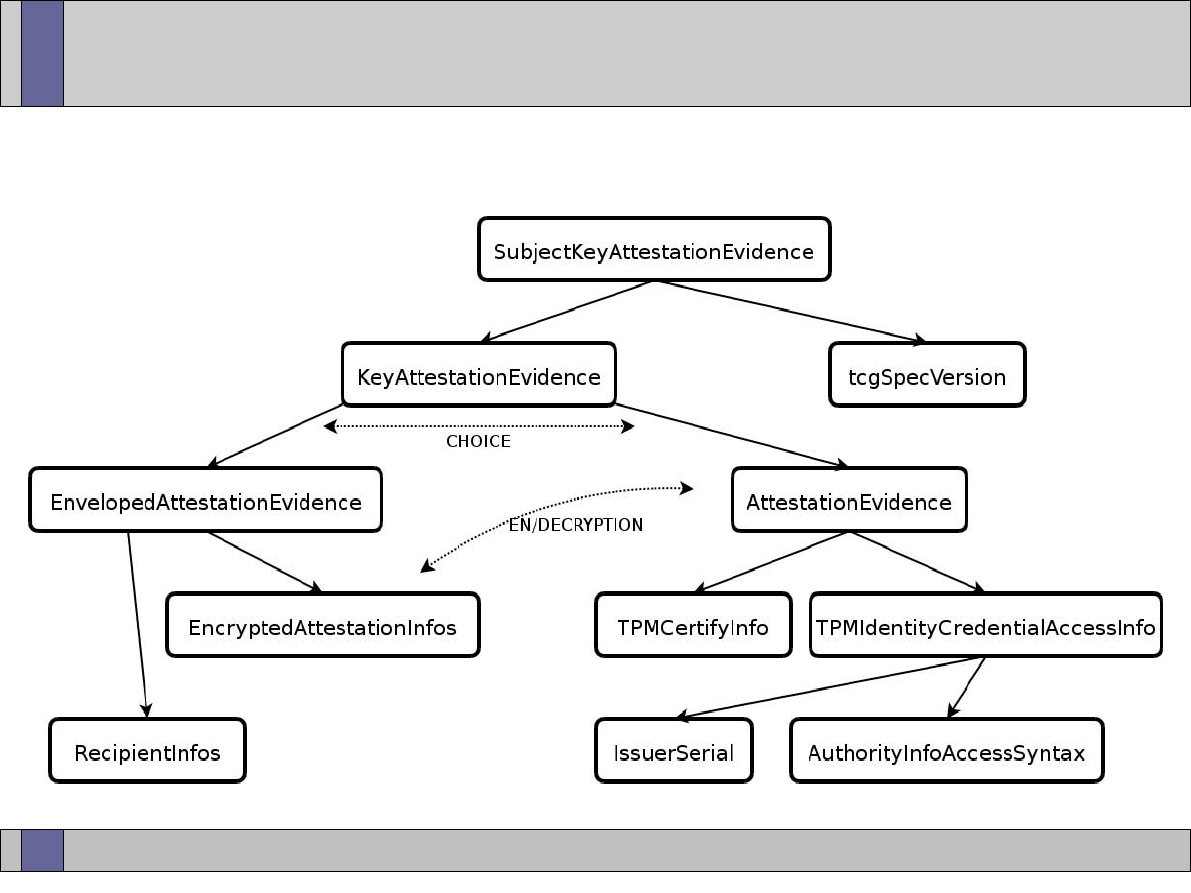
Trusted Computing Labs, IAIK TU Graz
35
Subject Key Attestation Evidence
●
SKAE ASN1 structure
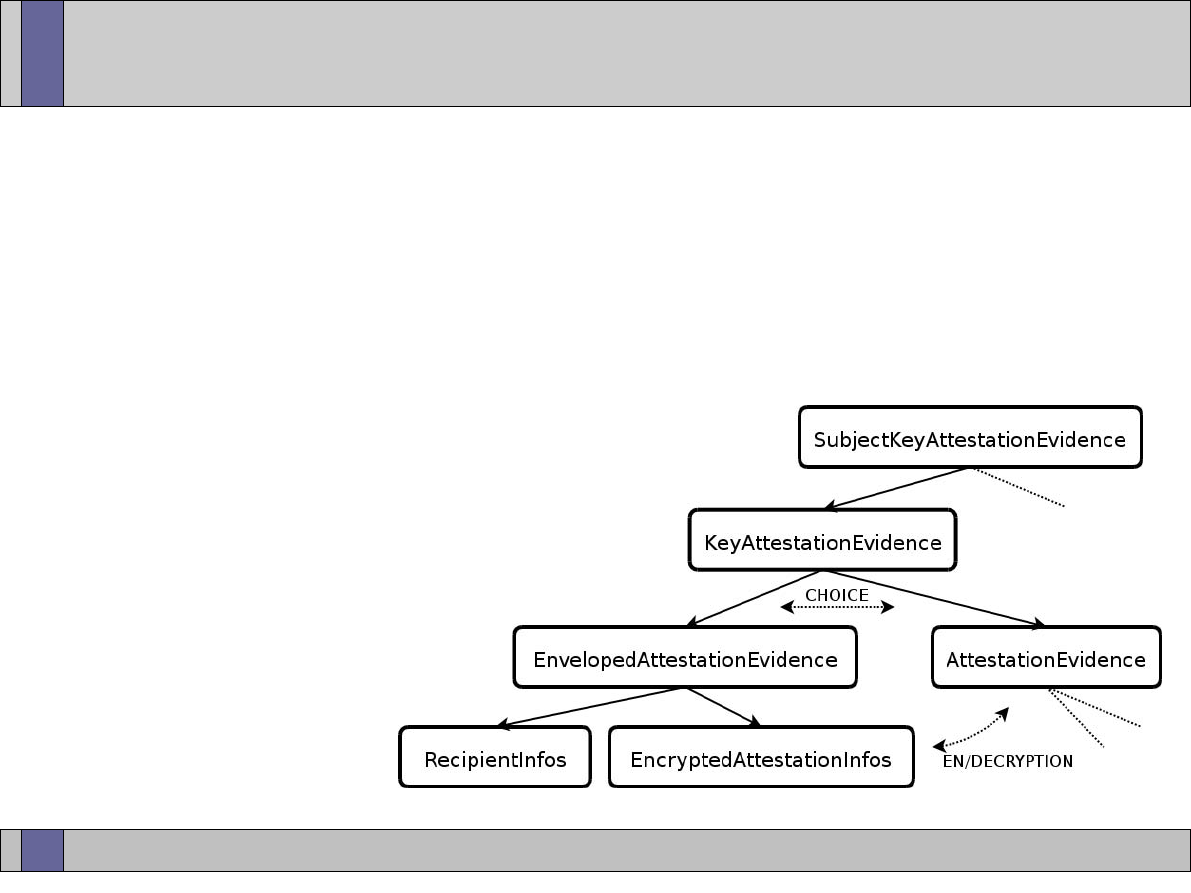
Trusted Computing Labs, IAIK TU Graz
36
Subject Key Attestation Evidence
●
SKAE extension comes in one of two variants
–
clear text
●
everyone can read AttestationEvidence contents
–
encrypted
●
list of eligible receivers in RecipientInfos
●
every RecipientInfo block contains
symmetric key for AttestationEvidence
decryption, encrypted with public
key of recipient
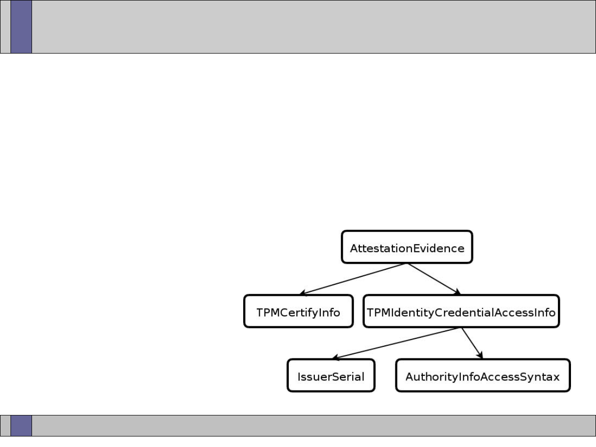
Trusted Computing Labs, IAIK TU Graz
37
Subject Key Attestation Evidence
●
content of attestation evidence
–
TPMCertifyInfo: TPM key structure + signature over structure with
AIK private key
–
IssuerSerial (optional component): reference to issuing authority and
serial number of AIK credential
–
AuthorityInfoAccessSyntax: information how to access authority of
AIK credential

Trusted Computing Labs, IAIK TU Graz
38
Subject Key Attestation Evidence
●
creating a certificate with SKAE extension
–
create TPM identity key “A”
–
obtain AIK certificate from Privacy CA for “A”
–
create new (non-migrateable) TPM key “B”
–
certify “B” with AIK key (TSS function Tspi_Key_CertifyKey)
●
result: certifyInfo structure
–
pre-assemble SKAE on client side or send all parts to CA
–
CA validates AIK certificate
–
CA validates certifyInfo structure
–
CA adds SKAE to normal certificate
–
CA builds / signs certificate

Trusted Computing Labs, IAIK TU Graz
39
Subject Key Attestation Evidence
●
validation steps
–
client offers certificate with SKAE extension
–
client offers proof of possession of private key
●
e.g. fresh signature on provided nonce
–
server validates proof of possession signature
–
server validates certificate with SKAE extension
–
server retrieves and validates AIK certificate referenced in SKAE
–
server validates certifyInfo structure in SKAE
–
if all tests ok, server is convinced that client has TPM and key in
certificate with SKAE is protected by TPM

Trusted Computing Labs, IAIK TU Graz
40
Subject Key Attestation Evidence
●
deployment scenario
–
"old" infrastructure does not know about SKAE
–
if "normal" certificate requires all extensions to be marked "critical"
(=all extensions must be known and how to read and interpret their
value) then SKAE cannot always be included
●
CA operation modes
–
CA includes SKAE only after successful validation of SKAE
●
must mention this in policy
–
CA does not validate SKAE at creation, just includes extension "as is"
●
SKAE validation later done by Relying party
–
CA validates SKAE, issues certificate without SKAE
●
must mention this in policy
–
certificate and SKAE always delivered in 2 separate pieces
●
trustworthy out-of-band distribution method needed, Relying party validates later

Trusted Computing Labs, IAIK TU Graz
41
Subject Key Attestation Evidence
●
security / privacy impact
–
after certification of key “B” there is no need to keep AIK private key
●
however, AIK certificate is long-term document
–
SKAE contains reference to AIK
●
correlation SKAE <--> AIK <--> EK <--> TPM maybe possible
–
options
●
always use one new AIK to create one new SKAE
–
maximum decoupling
●
design for trusted verifiers
–
only they can decrypt SKAE
–
need to be specified at build time
●
omit optional IssuerSerial reference
–
find trusted verifier using non-specified out-of-band mechanism

Trusted Computing Labs, IAIK TU Graz
42
Public Key Infrastructure
●
problem: certificates without context for validation are assertions
without proof (i.e. pretty worthless)
●
validation of assertions requires infrastructure to collect pieces of
information
●
currently almost zero public infrastructure for Trusted Computing
●
PKI as mass service poses scalability problems
●
some things are easy to check...
–
validity time
–
compare two certificates
–
recompute signature

Trusted Computing Labs, IAIK TU Graz
43
Public Key Infrastructure
●
...some issues are more tricky
–
locating original certificate issuer
–
compatible communication protocols between entities
–
different issuers, different issuing policies
●
still problematic for automation
–
revocation
●
CRL list vs. “online” query (OCSP)
●
always latency
–
validation of ALL certificate extensions and ensure they are
compatible for designated usage scenario
●
writing a certificate chain validator conforming to relevant RFCs,
processing all common extension options,
is a project of several man years...
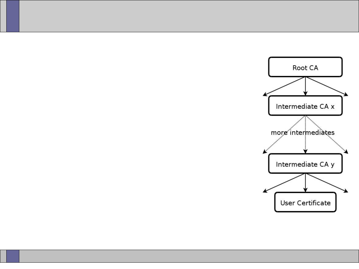
Trusted Computing Labs, IAIK TU Graz
44
PKI tree of trust
●
chain of trust in PKI
–
Root CA as trust anchor
–
a number of Intermediate CAs
–
leaf certificate in actual application use
●
validation of leaf certificate
–
reconstruct certificate chain from leaf
certificate to trusted root certificate
–
along the chain check all parts and
links for validity
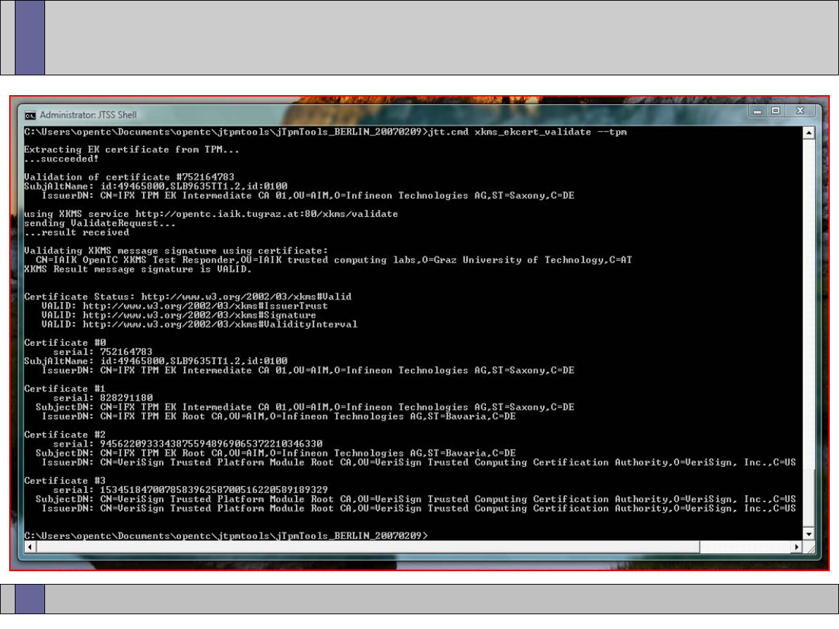
Trusted Computing Labs, IAIK TU Graz
45
PKI chain building
●
TRUSTED ROOT
LEAF CERTIFICATE
INTERMEDIATE CA
INTERMEDIATE CA

Trusted Computing Labs, IAIK TU Graz
46
PKI operations
●
certificate creation
–
different certificate types (EK, PE, AIK, ...) usually obtained/signed
from different certification authorities
●
certificate distribution
–
include on-chip (EK on TPM)
–
included with software (CD? OS?)
–
online service
●
search
–
locate copy of specific certificate by serial number, key, email,
AIK label, ...
–
no assertions about validity

Trusted Computing Labs, IAIK TU Graz
47
PKI operations
●
validation
–
status of binding is checked according to specific criteria
–
problem: automation, common format for policy description?
●
revocation
–
premature change of certificate status for external reasons
before end of official validity time
●
private key no longer in sole control of owner
●
replacement with newer version
●
suspension (set to on-hold)
●
...
●
"ripple" effect through PKI tree, one cert revocation can affect
many others

Trusted Computing Labs, IAIK TU Graz
48
PKI protocols
●
binary based
–
ASN1/DER encoded
–
compact
–
need support programs for view / decode / debug
●
XML based
–
easy to read, easier to debug
–
significant overhead of XML processing
●
problem in mobile or similar low resource environments
●
directory services
–
LDAP (lightweight directory access protocol)
●
status services
–
OCSP (online certificate status protocol)

Trusted Computing Labs, IAIK TU Graz
49
XKMS exchange example
<?xml
version=
"1.0"
encoding=
"UTF-8"
?>
<LocateRequest
xmlns
=
"http://www.w3.org/2002/03/xkms#"
[...]
Id
=
"_OP2MHIMWWG2FOABW7N769419BACO58T"
Service
=
"http://opentc.iaik.tugraz.at/xkms/aik"
>
<RespondWith>
http://www.w3.org/2002/03/xkms#X509Cert
</RespondWith>
<QueryKeyBinding>
<KeyInfo
xmlns
=
"http://www.w3.org/2000/09/xmldsig#"
>
<KeyName>
someLabel
</KeyName>
</KeyInfo>
</QueryKeyBinding>
</LocateRequest>
<?xml
version=
"1.0"
encoding=
"UTF-8"
?>
<LocateResult
xmlns
=
"http://www.w3.org/2002/03/xkms#"
[...]
Id
=
"MYF11V848QZ5UMM9BBCKFQROE384D263"
RequestId
=
"_OP2MHIMWWG2FOABW7N769419BACO58T"
ResultMajor
=
"http://www.w3.org/2002/03/xkms#Success"
Service
=
"http://opentc.iaik.tugraz.at/xkms/aik"
>
<Signature
xmlns
=
"http://www.w3.org/2000/09/xmldsig#"
>
[...]
</Signature>
<UnverifiedKeyBinding>
<KeyInfo
xmlns
=
"http://www.w3.org/2000/09/xmldsig#"
>
<X509Data>
<X509Certificate>
[...]
</X509Certificate>
</X509Data>
</KeyInfo>
</UnverifiedKeyBinding>
</LocateResult>

Trusted Computing Labs, IAIK TU Graz
50
More?
●
Trusted Computing Group Specifications
https://www.trustedcomputinggroup.org/specs/
–
“Credentials Profile Spec”
–
“Infrastructure Subject Key Attestation Evidence Extension”
–
“Reference Architecture for Interoperability”
–
“TCG Main Specification Version 1.1b”
–
“TCG TPM Specification Version 1.2 Revision ...”
●
IAIK TCcert, TCG style certificates tool
–
http://trustedjava.sourceforge.net/
●
script of IAIK class “IT-Sicherheit”
–
http://www.iaik.tugraz.at/teaching/02_it-sicherheit/index.php

Trusted Computing Labs, IAIK TU Graz
51
Open_TC EC Contract No: IST-027635
●
The Open_TC project is co-financed by the EC.
contract no: IST-027635
●
If you need further information, please visit our
website www.opentc.net or contact the coordinator:
Technikon Forschungs- und Planungsgesellschaft mbH
Richard-Wagner-Strasse 7, 9500 Villach, AUSTRIA
Tel. +43 4242 23355 0
Fax. +43 4242 23355 77
Email coordination@opentc.net
The information in this document is provided “as is”, and no guarantee or
warranty is given that the information is fit for any particular purpose.
The user thereof uses the information at its sole risk and liability.
Open Trusted Computing
Part 2 – TPM and TSS Implementations
Bora Güngören
Portakal Teknoloji
bora@portakalteknoloji.com

www.opentc.net
29 May 2007
2
Information on the Course
• These lecture notes have been prepared as part of EU
FP6 project Open Trusted Computing (OpenTC) by
Portakal Teknoloji (PORT).
• Major author for this specific slide set is Burak Oğuz
(PORT). Contributors include:
– Bora Güngören (PORT)

www.opentc.net
29 May 2007
3
Major Course Goal for Part 2
• The major goal of this part is to enable the student to
–
Understand and use in practice existing TPM
and TSS implementations for designing and
developing applications.
• This includes
– Roots of trust
– Key generation, storage and migration
– AIK's and DAA
– TSS layered hierarchy
– TPM protocols
– Setting up TPM/TSS and Java Wrapper
– Using existing TPM tools
– TPM/TSS Development
www.opentc.net
29 May 2007
4
What is TCG?
• Non-profit industrial-standards organization in behalf of
enhancing the security of the computing environment.
• Major goal of TCG is to develop Trusted Platform Module
and make trusted computing features available.
• TCG defines specifications about architectures, functions
and interfaces which can be used by software and
hardware vendors.
•
http://www.trustedcomputinggroup.org

www.opentc.net
29 May 2007
5
TCG Usage Scenerios
• Risk Management
• Asset Management
• E-Commerce
• Security Monitoring and Emergency Response
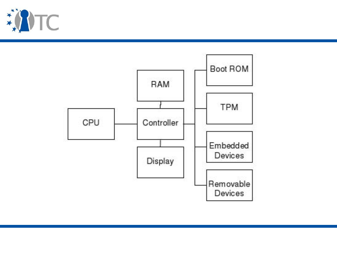
www.opentc.net
29 May 2007
6
TCG Architecture
• [1]

www.opentc.net
29 May 2007
7
Trusted Platforms
• Main aspects of a trusted platform include:
– Protected Capabilities and Shielded-Locations
• Protected capabilities are used in accessing shielded-locations
with exclusive rights.
– Attestation
• Attestation is the process of proving the correctness of the
information.
• An external entity can attest to shielded locations, protected
capabilities and Roots of Trust.

www.opentc.net
29 May 2007
8
Trusted Platforms
• Main aspects of a trusted platform include (cont'd):
– Attestation
• Attestation by TPM
• Attestation to the platform
• Atestation of the platform
• Authentication of the platform

www.opentc.net
29 May 2007
9
Trusted Platforms (2)
• Main aspects of a trusted platform include (cont'd)
– Integrity Measurement , Logging and Reporting
• Measure platform characteristics with given metrics
• Store the measurements
• Report the measurements

www.opentc.net
29 May 2007
10
Root of Trust
• Each Trusted Platform(TP) needs
– A set of “roots of trust”
– A root of trust also have to be trusted.
• TCG defined roots of trust are
– RTM (Roots of Trust for Measurement)
– RTS (Roots of Trust for Storage)
– RTR (Roots of Trust for Reporting)
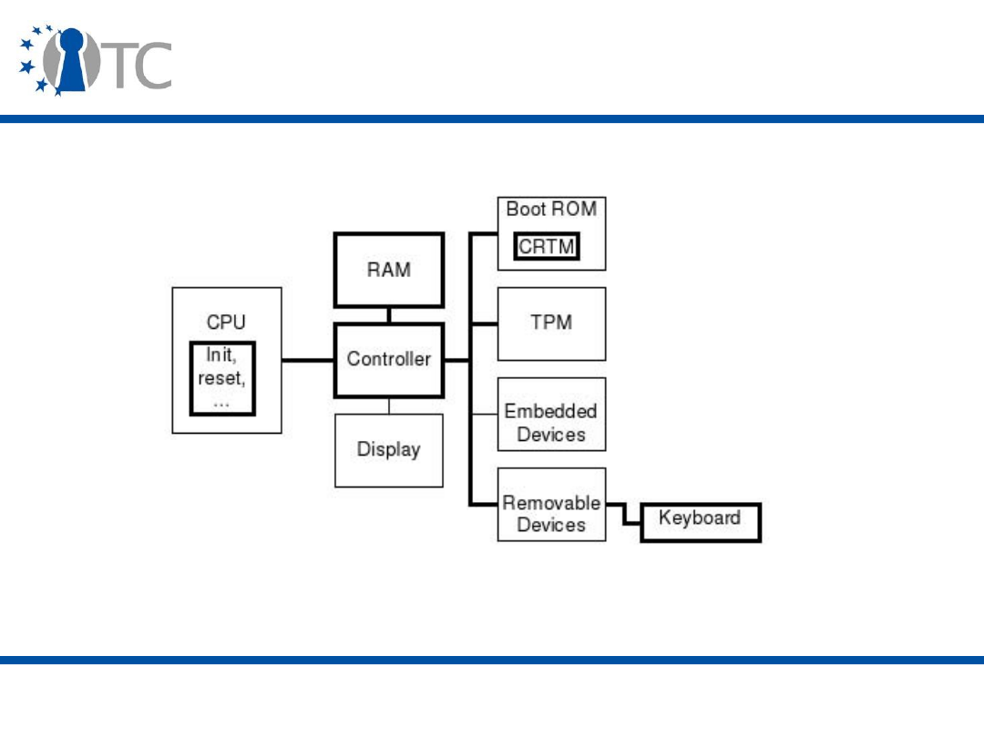
www.opentc.net
29 May 2007
11
Trusted Platform Architecture
• [1]
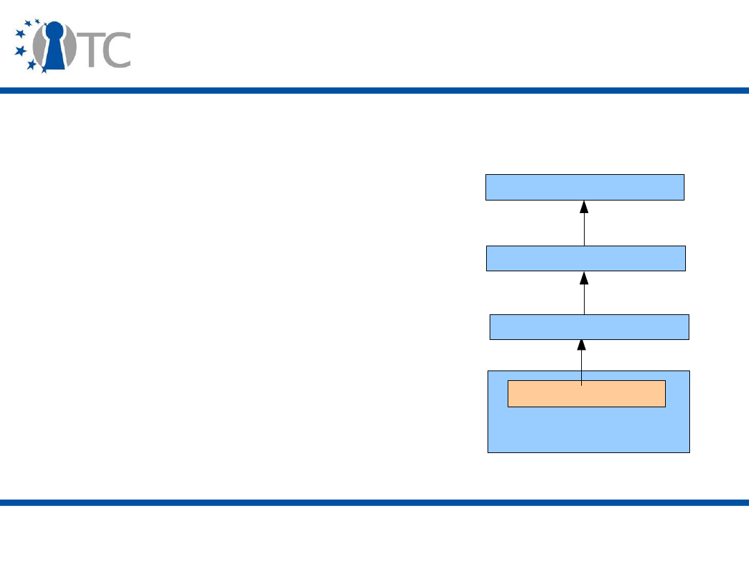
www.opentc.net
29 May 2007
12
Trusted Platform Architecture (2)
• A Trusted Platform has to show “Transitive Trust”
property.
Roots of Trust
CRTM
OS Loader
OS
Application
• In a system booting scenario
“Roots of Trust” trusts the CRTM
and runs it.
– Then CRTM measures OS Loader
and if measurement is reported
correct, CRTM gives execution
control to OS Loader.
• With this transitive execution
control,
– Applications will know that the
underlying OS is trusted
– OS knows applications that gets
execution control are trusted.

www.opentc.net
29 May 2007
13
Trusted Platform Architecture(3)
• Integrity Measurements are generated by measurement
events.
– Measure program code or data
– Take digest of measured data
• A digest of the measured data is the snapshot of the
current operational data
– The digest is kept by RTS and is reported by RTR.
– This operation yields a platform configuration.
• Storage Measurement Log (SML) holds related
measurement values.
– Platform configuration is valid if digest is same with the
value in SML.
– Digests are kept in Platform Configuration Registers (PCRs).

www.opentc.net
29 May 2007
14
Trusted Platform Architecture(4)
• Integrity Reporting is used in
– Exposing shielded-locations for storage of platform
configurations
– Attestation of authenticity according to the values in PCRs
• Integrity is reported with PCR values and platform
credentials.
– Integrity reporting will help identity management via
Attestation Identity Keys(AIKs) without disclosing
Endorsement Key(EK).
– Integrity reporting will help attestation of the platform via
credentials

www.opentc.net
29 May 2007
15
Endorsement Key (EK)
• The Endorsement Key is a 2048 bit RSA key pair
generated on each TPM.
– The EK is generated at TPM manufacture time and cannot
be modified afterwards.
• Each EK uniquely identifies a machine
– So, there are a lot of privacy concerns surrounding the EK.
– This is why the concept of an AIK was created.

www.opentc.net
29 May 2007
16
Attestation Identity Keys (AIK)
• An Attestation Identity Key is a key created for use in
attestation.
– At creation time, it gets tied to a TPM identity, which is in
turn tied to a TPM's Endorsement Key (EK).
– By this way, the AIK can be proven to be created by a
genuine TPM without exposing any part of the EK
• Exposing the EK itself would pose privacy concerns.
– There are still some privacy concerns using AIK's.
• If your Privacy CA and the person who's verifying your
attestation can co-operate, then it will be equivalent to using
the EK.

www.opentc.net
29 May 2007
17
Trusted Platform Architecture(5)
• Credentials over a Trusted Platform are
– Endorsement Credentials
– Conformance Credentials
– Platform Credentials
– Validation Credentials
– Identity Credentials

www.opentc.net
29 May 2007
18
Endorsement Credentials
• Endorsement Credentials are usually generated by
manufacturer.
– Also consumers will also generate Endorsement Credentials.
• Endorsement Credentials are generated by the entity who
generates the Endorsement Key.
www.opentc.net
29 May 2007
19
Endorsement Credentials
• Endorsement Credentials contain
– TPM Manufacturer name
– TPM part model, version/stepping
– EK pair public part
Endorsement Credentials
TPM Manufacturer Name
Endorsement Key Public Part
TPM Version or Stepping
TPM Part Model
www.opentc.net
29 May 2007
20
Conformance Credentials
• Conformance credentials indicate that whether the
underlying trusted platform building blocks and TPM are
evaluated and accepted by the evaulator.
Conformance Credentials
TPM Manufacturer Name
TPM Version or Stepping
TPM Part Model
Platform Manufacturer Name
Platform Version
Platform Model Number
Evaluator Name
www.opentc.net
29 May 2007
21
Platform Credentials
• Platform Credentials identify the platform's manufacturer
and other platform properties.
– They also contain Endorsement Credentials in order to
indicate association with TPM and Conformance Credentials.
– Platform Credentials are unique to a platform.
Platform Credentials
Platform Manufacturer Name
Endorsement Credentials
Platform Version
Platform Model Number
Conformance Credentials

www.opentc.net
29 May 2007
22
Attestation Identity Credentials
• Attestation Identity Credentials identify the AIK private
key used to sign the PCR values.
– A trusted third party service will issue this credential to
verify various credentials.
www.opentc.net
29 May 2007
23
Attestation Identity Credentials
• Attestation Identity Credentials identify the AIK private
key used to sign the PCR values.
Attestation Identity Credentials
TPM Manufacturer Name
AIK Public Part
TPM Part Model
Platform Manufacturer Name
TPM Conformance Credentials
Platform Model Number
Identity Label
Platform Conformance Credentials
Trusted Third Party

www.opentc.net
29 May 2007
24
Trusted Platform Architecture (6)
• Protected storage is managed by the RTS.
– The RTS uses a small amount of volatile memory to hold
keys while performing signing and decryption.
– So key disclosure is avoided.
– Inactive keys are stored on the disk devices and managed
by Key Cache Manager.

www.opentc.net
29 May 2007
25
Trusted Platform Architecture (6)
• There are two keys embedded in TPM
– Endorsement Key
– Storage Root Key(SRK)
• Endorsement Key is unique to the platform.
• SRK is the root key of all the keys on the platform
managed by the TPM.
– Deleting SRK by changing ownership will cause all data and
keys bound to TPM to get lost.
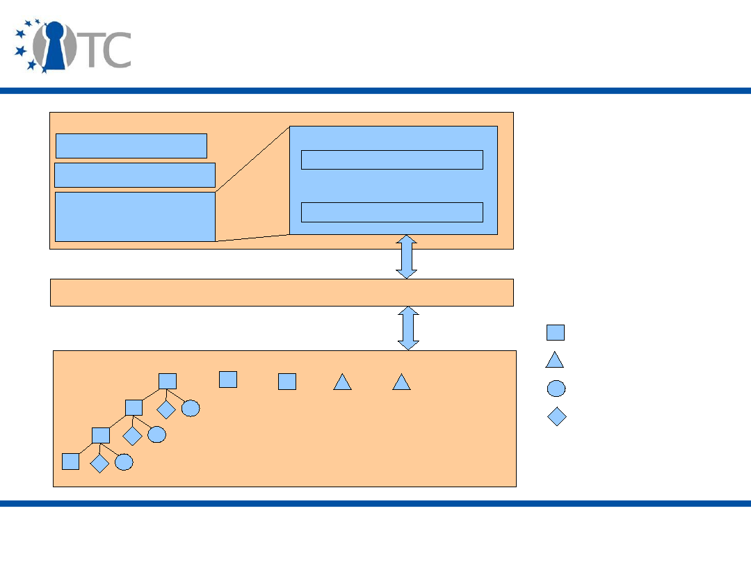
www.opentc.net
29 May 2007
26
Protected Storage
TPM / RTS
EK
SRK
Authorization Data
Keys
K1
Kn
.
.
.
Key Cache Manager(KCM)
Storage Device
...
...
...
...
Storage key
Opaque Data
Signing Key
AIK Key

www.opentc.net
29 May 2007
27
Key Types
• Signing Keys
– General purpose asymmetric singing keys.
• Storage Keys
– General purpose asymmetric keys to encrypt data and keys.
• Identity Keys (AIK)
– Non-migratable keys that can sign TPM capabilities and PCR
values.
• Endorsement Key
– Single non-migratable key for decrypting owner
authorization and messages associated with AIK creation.

www.opentc.net
29 May 2007
28
Key Types (cont'd)
• Bind Keys
– General purpose asymmetric keys to encrypt small amounts
of data.
• Legacy Keys
– Keys that are created outside the TPM.
– They can be used for signing and encryption.
– Legacy keys are migratable.
• Authentication Keys
– Symmetric keys that protect transport sessions.
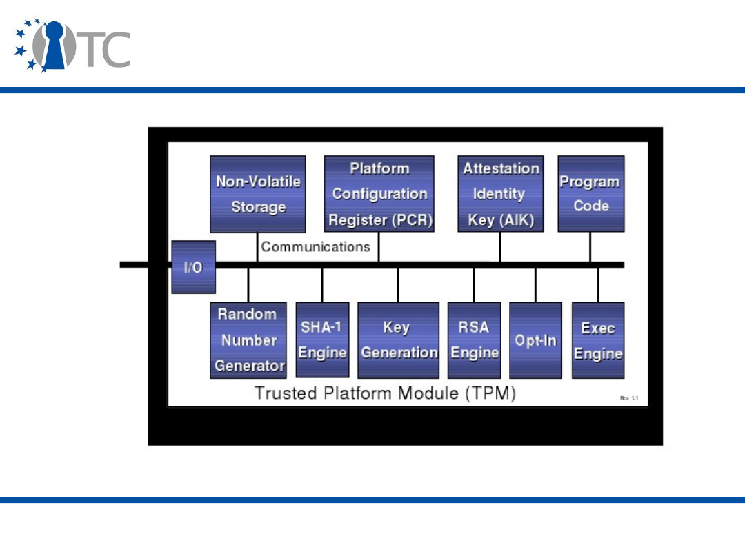
www.opentc.net
29 May 2007
29
Components of TPM
• [1]

www.opentc.net
29 May 2007
30
Components of TPM (2)
• I/O Component
– Information flow over communication bus
• Random Number Generator(RNG) Component
– True random bit generator
• SHA-1 Engine Component
– Message digest engine
• RSA Key Generation Component
– max. 2048-bit RSA key generator
• RSA Engine Component
– Responsible for signing, encryption/decryption with RSA
keys.

www.opentc.net
29 May 2007
31
Components of TPM (3)
• Opt-In Component
– Determines physical presence status and disabling
operations applied to other TPM components
• Execution Engine Component
– TPM initialization and measurement taking of TPM
• Non-Volatile Storage Component
– Used to store EK, SRK, owner data and status flag.
Optionally PCRs will be kept in NV Storage
• Attstation Identity Keys Component
– AIKs are stored in external storage as Blobs.
• Program Code Component
– Firmware to measure platform devices. (CRTM)

www.opentc.net
29 May 2007
32
Key TCG Capabilities
• Secure I/O
– Secure input and output (I/O) refers the path between the
computer user and the software is being trusted. That
means no maliciouse software can interrupt or intercept this
path.
• Memory Curtaining
– Full isolation of sensitive memory areas
• Sealed Storage
– Sealed storage protects private information by allowing it to
be encrypted using a key derived from the software and
hardware being used.

www.opentc.net
29 May 2007
33
Key TCG Capabilities (2)
• Remote Attestation
– The TPM v1.1b attestation process was defined to ensure
that the remote party that receives the attestation could
have a reasonable expectation that the information
presented is valid.
– Cryptographic techniques based on a platform-unique
cryptographic key are used achieve this design goal.
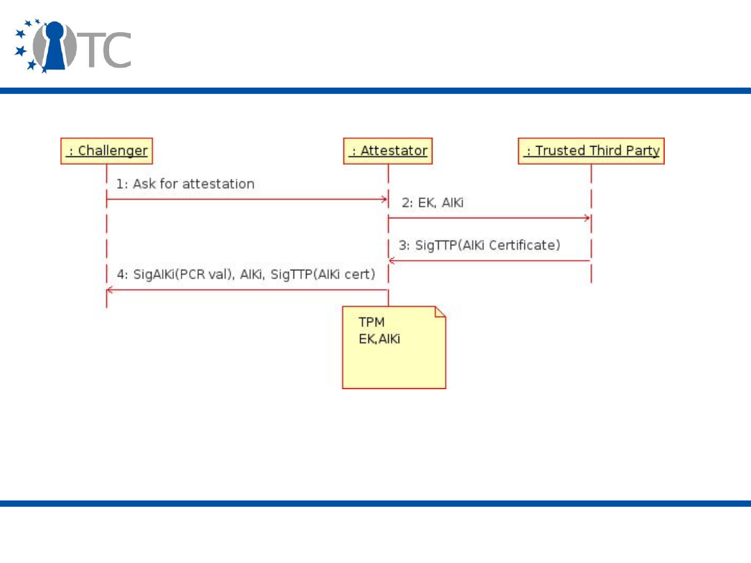
www.opentc.net
29 May 2007
34
Remote Attestation with Privacy CA

www.opentc.net
29 May 2007
35
TCG capabilities overview: V1.2
• New functionalities that come with V1.2 include
– Auditing
– Transport sessions
• Transport sessions give integrity and confidentiality protection
to commands sent to TPM and logs the given commands.
– Non-volatile monotonic counters
• Prevents replay attacks and increases the security of the
system.

www.opentc.net
29 May 2007
36
TCG capabilities overview: V1.2
• New functionalities that come with V1.2 are
– Delegation
• Delegation allows an Owner to delegate some Owner-
authorized TPM functionalities to other entities.
– Context saving
• Context saving allows efficient shared use of TPM by different
software layers.

www.opentc.net
29 May 2007
37
TCG capabilities overview: V1.2
• New functionalities that come with V1.2 are
– Non-volatile Storage
• NV Storage allows TPM Owner or User to allocate NV Storage
areas with a rich set of control attributes such as direct
authorization of read and write based on Locality or platform
integrity.
– Secure timing
• It is possible to do something similar by correlating a tick
counter with an external time stamping source, and then using
the TPM to do secure time stamping that piggybacks off the
external time source.

www.opentc.net
29 May 2007
38
TCG capabilities overview: V1.2
– Direct proof (DAA)
• While the Trusted Third Party model for AIK creation can
achieve necessary privacy characteristics, it still disclosures
the EK of platform to the Third Party.
• DAA was designed as a Zero Knowledge Proof and allows a
computing platform to directly attest to platform
characteristics without the use of Trusted Third Party as an
intermediary.
•
http://www.zurich.ibm.com/security/idemix/
– Locality
• Locality allows external hardware/software processes to have
different security and trustworthiness levels.

www.opentc.net
29 May 2007
39
TCG capabilities overview: V1.2
– Identity generation
• Identity certificates can now be locked to PCRs and locality,
and “soft” identities, whose private key does not reside in the
TPM can now be created.
– PCR use
• It used to be the case that the same PCRs were recorded at
creation and unseal – now each can be specified separately. In
addition, PCR 15 has been reserved for software testing, and
can be reset without problem. In addition, some PCRs can be
set to be resettable only when the TPM in in a specific locality
state. Moreover, PCR count increased from 16 to 24.
– Authenticaion
• Authentication necessary to use a key used to be either
through an HMAC or PCR values (or both). Now locality can also
be used as well

www.opentc.net
29 May 2007
40
TCG capabilities overview: V1.2
– New signing key types
• New varieties of keys with restricted usage
– New types of migratable keys
• Certified Migratable Keys
– New flexibility in EKs
• Since attestation has the risk disclosuring EK, V1.2
specifications allows manufacturer to allow the key to be
regenerated.
– New attributes
• As locality attributes on PCRs

www.opentc.net
29 May 2007
41
Direct Anonymous Attestation (DAA)
• Idea: do not provide certificate but use cryptographic
proof that you have one
• 1.
– Generate DAA key
– Get signature (certificate) on DAA key from DAA issuer
• 2.
– Prove that
• you generated sign. by DAA key on AIKi, Verifier, Time
• you possess sign. by DAA issuer on DAA key
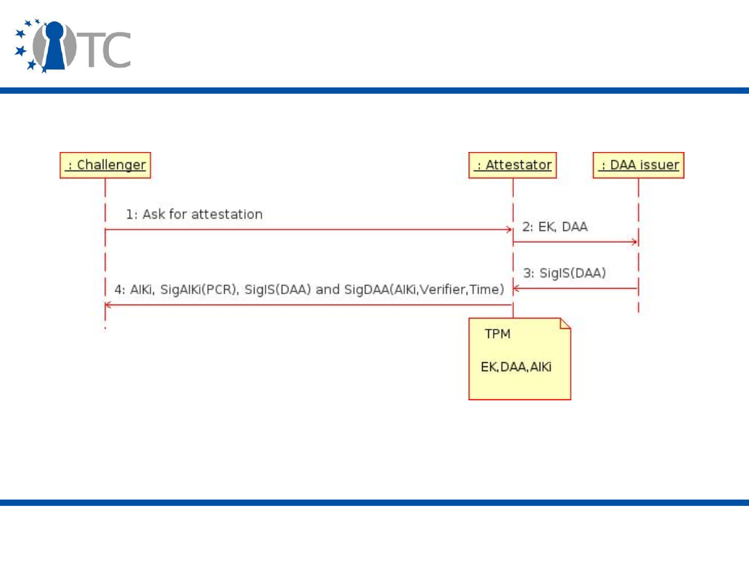
www.opentc.net
29 May 2007
42
Direct Anonymous Attestation (DAA)
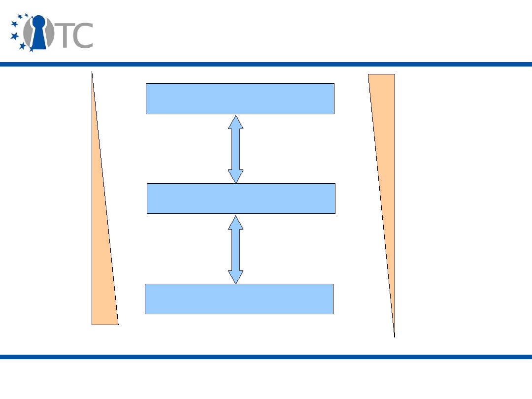
www.opentc.net
29 May 2007
43
Identification and Anonymity
Full Identification
Full Anonymity
Pseudonymity
P
ri
v
a
c
y
A
tt
ri
b
u
t
e
s

www.opentc.net
29 May 2007
44
Identity Problem with Remote
Attestation
• Need to get new certificate per key: Privacy CA is a bottle
neck
• Needs to be highly secured which contradicts availability
• If Privacy CA and verifier collude, they still can link
• No business model for Privacy CA
– users need to trust Privacy CA not to collaborate with
challenger, so Privacy CA cannot be run by Service
Providers (Challengers)
– Challengers need to trust Privacy CA to only issue to valid
TPM, so Privacy CA cannot be run by user/consumer
organization
• [5]
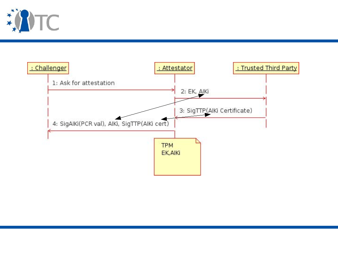
www.opentc.net
29 May 2007
45
Remote Attestation with Privacy CA

www.opentc.net
29 May 2007
46
Solution - DAA
• DAA issuer and Verifier cannot link, i.e., could even be the
same entity: this solves business model problem of
Privacy CA
– Certificate can SigIS(DAA) could be public
• DAA certificate needs to be issued only once: no
bottleneck
• DAA certificate can be
– issued by manufacturer
– by buyer of platforms (e.g., secure intranet access)
• [5]

www.opentc.net
29 May 2007
47
Roles on TPM
• Entities perform functions on the TPM. These functions
are performed while acting in one of the following roles:
– TPM Owner
• This is the entity that owns the platform. There is only one TPM
owner of the platform. Proof of ownership is the presentation of
authentication data. If owner wants to share ownership, should
use delegation.
• TPM owner would be the IT department in a corporate
environment.
• In home environment TPM pwner should be the person who
owns the computer.

www.opentc.net
29 May 2007
48
Roles on TPM (2)
• Entities perform functions on the TPM. These functions
are performed while acting in one of the following roles:
– TPM User
• These are entities that can load or use TPM objects such as
TPM keys. It is important to understand that the TPM itself does
not maintain a list of TPM users. A TPM user is any entity that
can present the authentication data for an object. The first TPM
user is created by the TPM owner. Thereafter more TPM users
can be created by either the TPM owner or other TPM users. A
TPM user is not necessarily a human. A TPM user may be
service provider such as a mail or file server.
• An employee or servers of the corporation would be a TPM User
in corporate environment.
• In home environment a household will be a TPM User.

www.opentc.net
29 May 2007
49
Roles on TPM (3)
• Entities perform functions on the TPM. These functions
are performed while acting in one of the following roles:
– Platform Administrator
• This is the entity that controls the platform’s OS, filesystem, or
data. The Platform administrator may or may not be the TPM
owner.
– Platform User
• These are entities that the Platform administrator allows use of
the data or resources of the platform. The Platform users may
or may not be TPM users.

www.opentc.net
29 May 2007
50
Roles on TPM (4)
• Entities perform functions on the TPM. These functions
are performed while acting in one of the following roles:
– Operator
• The human physically at the platform able to directly operate it
and observe physicalindications. The operator may or may not
be a TPM owner or TPM user but will likely be either a Platform
administrator or Platform user.
– Public
• Performs any function on either the platform’s OS, filesystem,
or data allowed without an identity or authentication. Performs
any function on the TPM that does not require authentication.

www.opentc.net
29 May 2007
51
TCG Execution Model
• Execution model for a TCG compliant TPM begins when
TPM first receives power.
– TPM has states each designed to permit orderly deployment
and maintenance of computing resource while balancing the
needs of other entities.
• TPM operational states are :
– Enabled / Disabled
– Activated / Deactivated
– Owned / Un-owned

www.opentc.net
29 May 2007
52
TPM Operational States
Operating State
Activated - Temporal
Activated - Persistent
Owned
Ownership Enabled
Enabled (by Anyone)
Enabled (by Owner)
Changing via Remote
Operation
Default Value
False
True
False
False
False
False
Yes
No
No
No
No
No
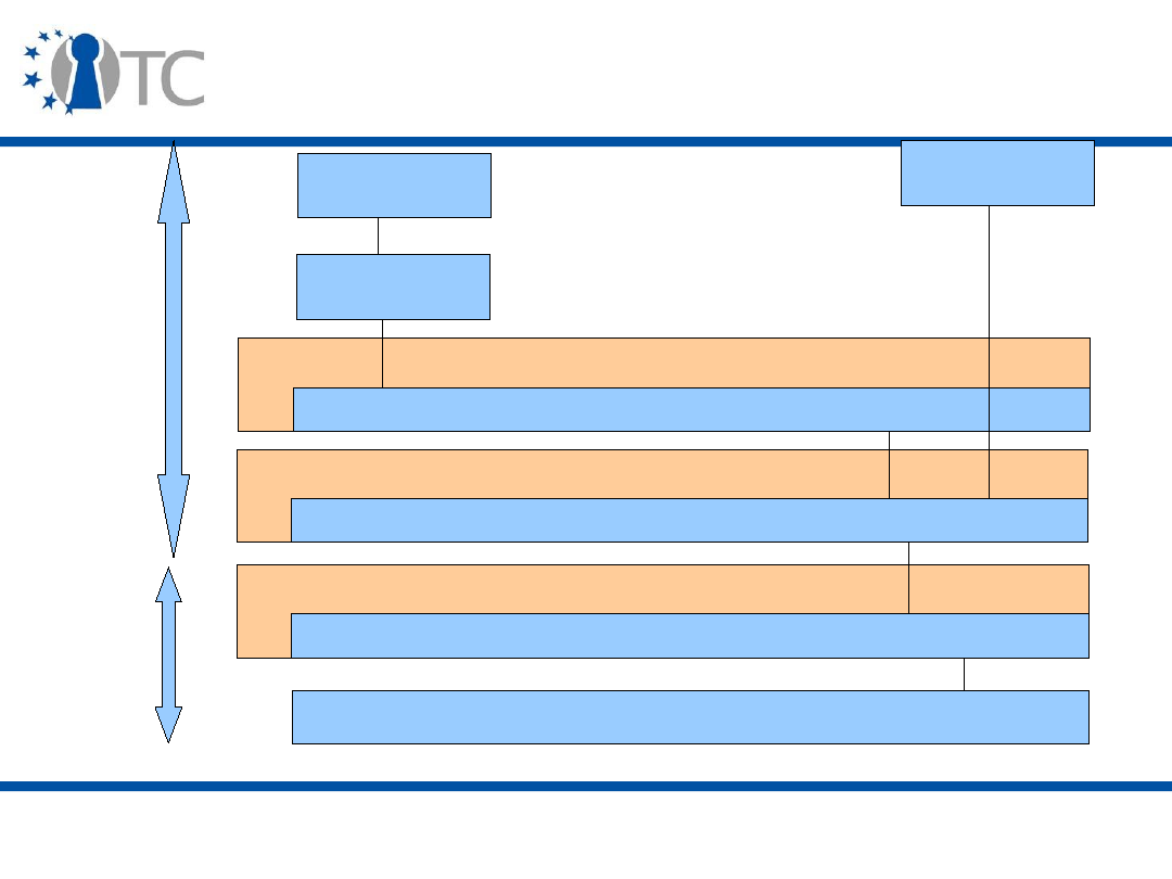
www.opentc.net
29 May 2007
53
Tddli Interface
TSS Architecture
TPM
TCG Device Driver Library
Tcs Interface
TSS Core Service
Tspi Interface
TSS Service Provider
TSS Remote
Application
TCG Local
Application
Crypto Service
Provider
Kernel
Mode
User
Mode

www.opentc.net
29 May 2007
54
TDDL (TCG Device Driver Library)
• TDDL exists between TCS and TPM Device Driver.
– TDDL provides a user mode interface library for TCS.
• TDDL
– Ensures different implementations of the TSS properly
communicate with any TPM.
– Provides an OS-independent interface for applicataions.
– Allows TPM vendor to provide a software TPM simulator as a
user mode component.

www.opentc.net
29 May 2007
55
Tddli – TDDL Interface
• Three types of functions can be described within the
TDDL interface:
– Maintenance functions such as Open, Close, GetStatus
which maintain communication with TPM device driver
– Indirect functions such as GetCapability, SetCapability to
get and set attributes of TPM, TPM device driver and TDDL.
– Direct functions such as Transmit, Cancel for transmission
of commands to TPM.

www.opentc.net
29 May 2007
56
TCS and Tcsi
• TCS provides a common set of services per platform for
all service providers.
– Since the TPM is not required to be multithreaded, it
provides threaded access to TPM.
• Tcsi is a simple library where each operation is atomic.
– It resides as a system process separate from application
and service provider processes.
– Communication between service provider and TCS will be
implemented as an RPC.

www.opentc.net
29 May 2007
57
TSP (TSS Service Provider)
• This module provides TCG services for applications.
– TSP provides the high-level TCG functions allowing
applications to focus on their specialty while relying on the
TSP to perform most of the trusted functions provided by
the TPM.
– TSP also provides a small number of auxiliary functions for
convenience. These are not provided by the TPM
• i.e. signature verification.
• There will be one TSP per application

www.opentc.net
29 May 2007
58
TSPI (TSP interface)
• The interface to the TSP is the TSP Interface (TSPI).
– This is an object oriented interface.
– It resides within the same process as the application.
– In some implementations it may be trusted with sensitive
data such as authorization data to the same extent as the
application itself.
• This may be required for functions where the application
gathers the object’s authentication data from the user and
passes it to the TSP for processing into the command’s
authentication data format.

www.opentc.net
29 May 2007
59
Cryptographic Infrastructures
• There exists several general purpose Cryptographic
infrastructures available to the industry.
– Examples are MS-CAPI, PKCS #11.
• TSS does not provide bulk, general purpose symmetric
encryption/decryption.
– These functions will be provided by these cryptographic
infrastructures externally to TSS.
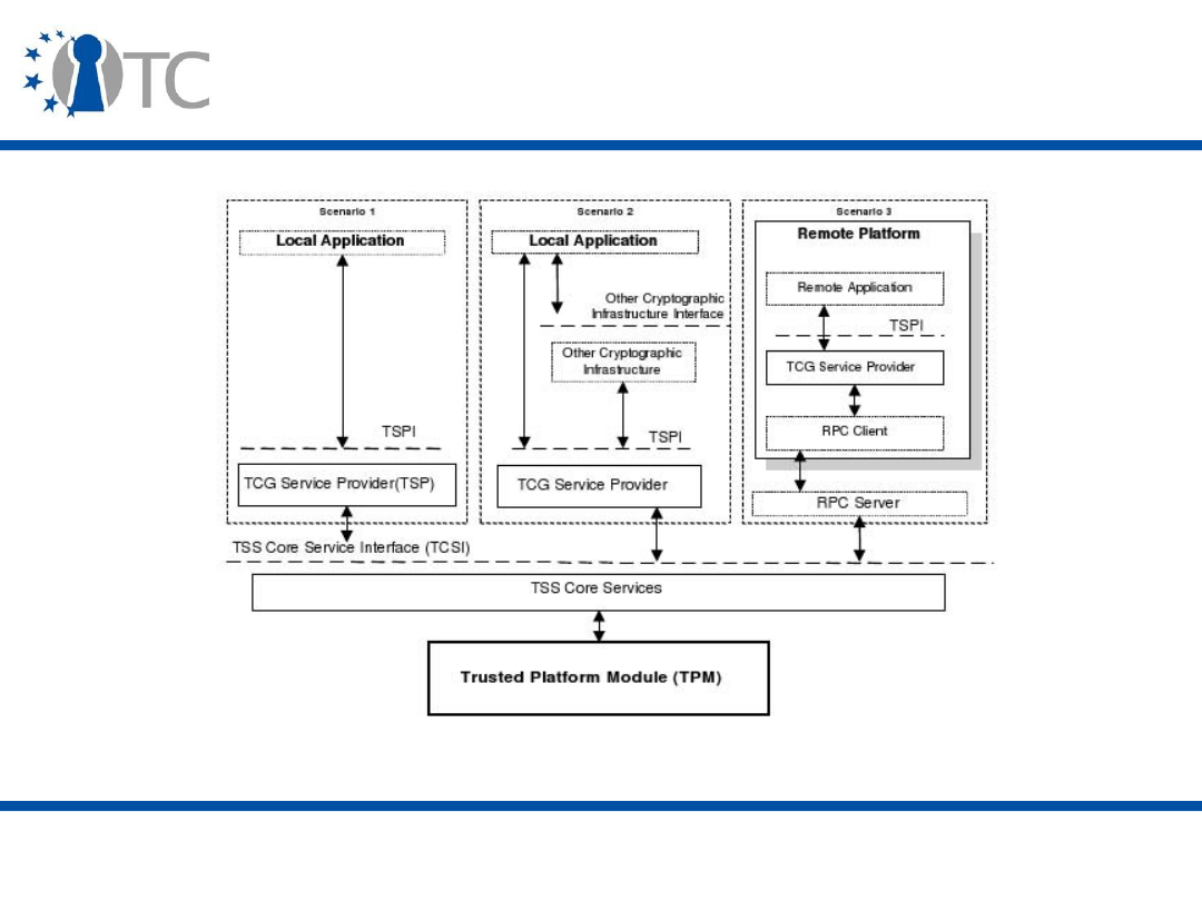
www.opentc.net
29 May 2007
60
Application Interaction
• [1]

www.opentc.net
29 May 2007
61
Communication between TSS and TPM
• Some of the TSS commands have to be authorized in
order to access to TPM.
• Authorization protocols used between TSS and TPM are
– Object Independent Authorization Protocol (OIAP) : OIAP
protocol establishes an authorized clear-text session
between the TPM and an external entity. TCS provides
useful features to manage OIAP sessions.
– Object Specific Authorization Protocol (OSAP) : OSAP is very
similar to OIAP in design and concept. Authorized session is
bound to a TPM object and it computes an ephemeral
secret.

www.opentc.net
29 May 2007
62
Communication between TSS and TPM(2)
• Authorization protocols used between TSS and TPM are
– Authorization Data Insertion Protocol (ADIP) : ADIP protocol
is used when a caller desires to instantiate new TPM
managed objects.
– Authorization Data Change Protocol (ADCP) : This protocol is
used in updating authorization data for TPM managed
objects.
– Asymmetric Authorization Change Protocol (AACP) : This
protocol allows a child's authorization data to be changed
without the parent learning the child's authorization data.

www.opentc.net
29 May 2007
63
Programming TSS
• Currently available open source TCG Software Stacks are
on v1.1.
– TrouSerS is an open source TCS daemon.
• TSS functions are prefixed with the module name.
– For example, TCG Core Services interfaces have the “Tcsi_”
prefix; TCG Service Provider interfaces have the “TSPI_”
prefix; and TCG Device Driver interfaces have the “Tddli_”
prefix.

www.opentc.net
29 May 2007
64
Programming TSS (2)
• Services provided with version 1.1 TSS are
– RSA key pair generation
– RSA encryption and decryption using PKCS v1.5 and OAEP
padding
– RSA sign/verify
– Extend data into the TPM's PCRs and log these events
– Seal data to arbitrary PCRs
– Random Number Generation
– RSA key storage

www.opentc.net
29 May 2007
65
TrouSerS – TSS
• TrouSerS is an CPL (Common Public License) licensed
Trusted Computing Software Stack.
• TrouSerS is supported on i386 GNU/Linux.
• Requirements for Trousers are
– automake > 1.4
– autoconf > 1.4
– pkgconfig
– libtool
– gtk2-devel
– openssl >= 0.9.7
– openssl-devel >= 0.9.7
– pthreads library (glibc-devel)
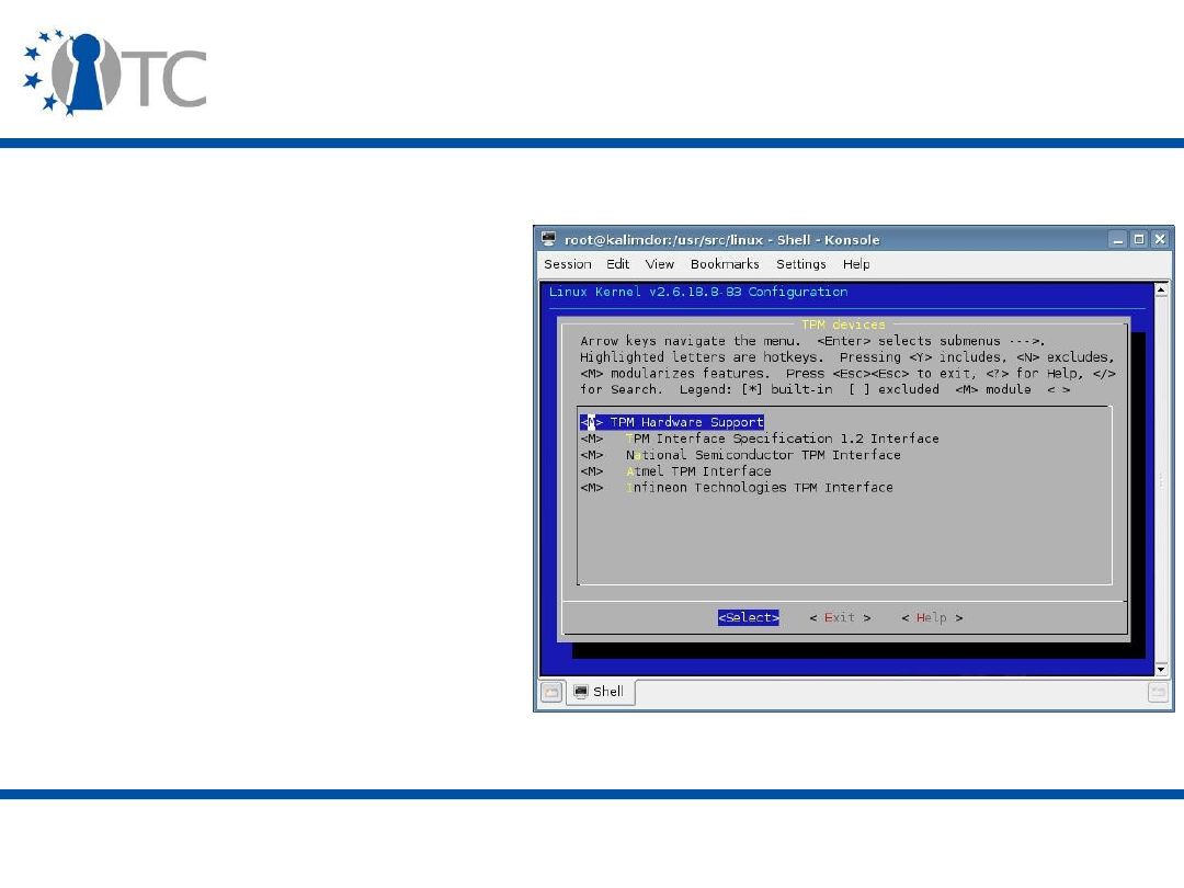
www.opentc.net
29 May 2007
66
Building TrouSerS on 32 bit GNU/Linux
• Device driver should be
installed. All TPM drivers
are stable for 2.6.18 or
later Linux Kernels.
• If device drivers are not
installed, you can re-
compile your kernel with
adding devices under
Device Derivers->
Character Devices->
TPM Devices

www.opentc.net
29 May 2007
67
Building TrouSerS on 32 bit GNU/Linux(2)
• To build trousers after you have the device driver
installed:
$ sh bootstrap.sh
$ ./configure [--enable-debug] [--enable-gprof] [--enable-
gcov]
$ make
# make install
• For Infineon v1.2 TPMs you should patch Trousers with
IAIK's patch.

www.opentc.net
29 May 2007
68
Building TrouSerS on 32 bit GNU/Linux(3)
• Default locations of files that TrouSerS installs:
– /usr/local/sbin/tcsd
– /usr/local/etc/tcsd.conf
– /usr/local/lib/libtspi.so.0.0.X
– /usr/local/lib/libtspi.so.0 -> libtspi.so.0.0.X
– /usr/local/lib/libtspi.so -> libtspi.so.0.0.X
– /usr/local/lib/libtspi.la
– /usr/local/lib/libtddl.a
– /usr/local/var/lib/tpm

www.opentc.net
29 May 2007
69
Running TrouSerS on 32 bit GNU/Linux
• First insert TPM device driver module to Kernel.
# modprobe tpm_tis
• Then start TrouSerS
# startproc -u tss /usr/local/sbin/tcsd
• In order to take the ownership of TPM, you can use TPM
Tools.
# tpm_takeownership
• If any error occurs relatedd with TPM status, check TPM
status from BIOS.
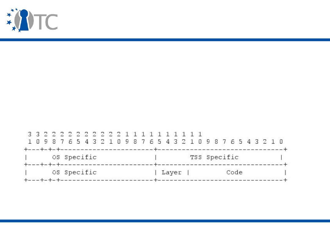
www.opentc.net
29 May 2007
70
TSS Return Codes
• Layer codes (Bit #12 to Bit #15) :
– TPM
0x0
– TDDL
0x1
– TCS
0x2
– TSP
0x3
• [2]

www.opentc.net
29 May 2007
71
Common Return Codes
• Error code information (Bit #0 to Bit #11) :
– TSS_SUCCESS
Success
– TSS_E_FAIL
Non-Specific failure
– TSS_E_BAD_PARAMETER
One or more parameter is
bad
– TSS_E_INTERNAL_ERROR
An internal SW error has
been detected
– TSS_E_NOTIMPL
Not implemented
– TSS_E_PS_KEY_NOTFOUND
The key cannot be found in
the persistent storage
database
– ........

www.opentc.net
29 May 2007
72
Compile and Run TrouSerS Codes
• #include<tss/tspi.h>
• Add libtspi.so to LD_PATH and headers to include path.
• gcc mytssapp.c -o mytssapp -ltspi

www.opentc.net
29 May 2007
73
TSS Object Types
• There are many objet types in TSS.
– TSS_HCONTEXT
– TSS_HPOLICY
– TSS_HTPM
– TSS_HKEY
– TSS_HENCDATA
– TSS_HPCRS
– TSS_HHASH
– TSS_HNVSTORE
– TSS_HMIGDATA
– TSS_HDELFAMILY
– TSS_HDAA

www.opentc.net
29 May 2007
74
TSPI – Common Methods
• These methods are common to all TSP classes
– Tspi_SetAttribUint32
– Tspi_GetAttribUint32
– Tspi_SetAttribData
– Tspi_GetAttribData
– Tspi_ChangeAuth
– Tspi_ChangeAuthAsym
– Tspi_GetPolicyObject

www.opentc.net
29 May 2007
75
TSPI – Context Class Methods
• These methods do container management for TPM
managed objects. This includes caching and external
object archival.
– Tspi_Context_Create
– Tspi_Context_Close
– Tspi_Context_Connect
– Tspi_Context_FreeMemory
– Tspi_Context_GetDefaultPolicy
– Tspi_Context_CreateObject
– Tspi_Context_CloseObject
– Tspi_Context_GetCapability

www.opentc.net
29 May 2007
76
TSPI – Context Class Methods (2)
• These methods do container management for TPM
managed objects. This includes caching and external
object archival.
– Tspi_Context_GetTPMObject
– Tspi_Context_LoadKeyByBlob
– Tspi_Context_LoadKeyByUUID
– Tspi_Context_RegisterKey
– Tspi_Context_UnregisterKey
– Tspi_Context_DeleteKeyByUUID
– Tspi_Context_GetKeyByUUID
– Tspi_Context_GetKeyByPublicInfo
– Tspi_Context_GetRegisteredKeysByUUID

www.opentc.net
29 May 2007
77
TSPI – Create and Connect Context
• An application developer should first open a context in
order to create and operate on objects.
• In order to open a new context
TSS_HCONTEXT
hContext;
TSS_RESULT
result;
result = Tspi_Context_Create(&hContext);
result = Tspi_Context_Connect(hContext, NULL);
• Close context
Tspi_Context_FreeMemory( hContext, NULL );
result = Tspi_Context_Close(hContext);

www.opentc.net
29 May 2007
78
TSPI – Create objects
• Creating a signature key.
TSS_HCONTEXT
hContext;
TSS_HKEY
hSignatureKey;
TSS_RESULT result;
result = Tspi_Context_Create(&hContext);
result = Tspi_Context_Connect(hContext, NULL);
result = Tspi_Context_CreateObject(hContext,
TSS_OBJECT_TYPE_RSAKEY, TSS_KEY_SIZE_2048 |
TSS_KEY_TYPE_SIGNING |TSS_KEY_MIGRATABLE,
&hSignatureKey);

www.opentc.net
29 May 2007
79
TSPI – Get TPM Object
TSS_HCONTEXT
hContext;
TSS_HTPM
hTPM;
TSS_RESULT result;
result = Tspi_Context_Create( &hContext );
result = Tspi_Context_Connect( hContext,NULL);
result = Tspi_Context_GetTpmObject( hContext,
&hTPM );

www.opentc.net
29 May 2007
80
TSPI – Load Key By UUID
• Get Storage Root Key handle.
– SRK has special UUID called TSS_SRK_UUID.
– In order to use SRK, developer should set SRK secret by
using SRK policy object.

www.opentc.net
29 May 2007
81
TSPI – Load Key By UUID
• Get Storage Root Key handle.
TSS_HKEY
hSRK;
TSS_HPOLICY srkUsagePolicy;
// create and connect to context
// get tpm object
result = Tspi_Context_LoadKeyByUUID(hContext,
TSS_PS_TYPE_SYSTEM, TSS_SRK_UUID, &hSRK);
result = Tspi_GetPolicyObject(hSRK,
TSS_POLICY_USAGE, &srkUsagePolicy);
result = Tspi_Policy_SetSecret(srkUsagePolicy,
TSS_SECRET_MODE_PLAIN,strlen(“pass”), “pass”);

www.opentc.net
29 May 2007
82
TSPI – Registering New Key to TPM
• Register a new key under SRK. New keys will be wrapped
only by storage keys.
TSS_HKEY
hKey;
TSS_UUID
migratableSignUUID={1, 2, 3, 4, 5, 6, 7, 8,
9, 10, 2};
// create and connect to context
// get tpm object
// load SRK Key
result = Tspi_Context_CreateObject(hContext,
TSS_OBJECT_TYPE_RSAKEY,initFlags, &hKey);
result = Tspi_Key_CreateKey(hKey, hSRK, 0);
result = Tspi_Context_RegisterKey(hContext,
hKey, TSS_PS_TYPE_SYSTEM, migratableSignUUID,
TSS_PS_TYPE_SYSTEM, SRK_UUID);

www.opentc.net
29 May 2007
83
TSPI – Get Capabilities
• Query whether an algorithm is supported
TSS_FLAG
capArea= TSS_TCSCAP_ALG;
UINT32
subCap = TSS_ALG_AES;
BYTE**
prgbRespData;
UINT32*
pulRespDataLength;
// create and connect to context
result = Tspi_Context_GetCapability(hContext,
capArea, ulSubCapLength, (BYTE *)&subCap,
pulRespDataLength, prgbRespData);

www.opentc.net
29 May 2007
84
TSPI – Policy Class Methods
• These methods manage authentication and authorization
policies for TPM managed objects.
– Tspi_Policy_SetSecret
– Tspi_Policy_FlushSecret
– Tspi_Policy_AssignToObject

www.opentc.net
29 May 2007
85
TSPI – Assign Policies to Objects
• Each context has its own default policy object.
• The policy object is
– Automatically assigned to a new key or encrypted data
object after its creation.
• Different policy object can be assigned with function
Tspi_Policy_AssignToObject(…).

www.opentc.net
29 May 2007
86
TSPI – Assign Policies to Objects
• Each context has its own default policy object.
TSS_HPOLICY hPolicy;
// create and connect to context
// get tpm object
result = Tspi_Context_GetDefaultPolicy ( hContext,
&hPolicy );
result = Tspi_Policy_SetSecret(hPolicy,
TSS_SECRET_MODE_PLAIN,strlen(“pass”), “pass”);
// create key
result = Tspi_Policy_AssignToObject(hPolicy,hKey);

www.opentc.net
29 May 2007
87
TSPI – TPM Class Methods
• These methods facilitate management of the TPM and
platform configuration measurement and reporting.
– Tspi_TPM_CreateEndorsementKey
– Tspi_TPM_GetPubEndorsementKey
– Tspi_TPM_TakeOwnership
– Tspi_TPM_CollateIdentityRequest
– Tspi_TPM_ActivateIdentity
– Tspi_TPM_ClearOwner
– Tspi_TPM_SetStatus
– Tspi_TPM_GetStatus
– Tspi_TPM_SelfTestFull
– Tspi_TPM_CertifySelfTest
– Tspi_TPM_GetTestResult

www.opentc.net
29 May 2007
88
TSPI – TPM Class Methods
– Tspi_TPM_GetTestResult
– Tspi_TPM_GetCapability
– Tspi_TPM_GetCapabilitySigned
– Tspi_TPM_KillMaintenanceFeature
– Tspi_TPM_LoadMaintenancePubKey
– Tspi_TPM_CheckMaintenancePubKey
– Tspi_TPM_GetRandom
– Tspi_TPM_StirRandom
– Tspi_TPM_AuthorizeMigrationTicket
•
– Tspi_TPM_GetEvent
– Tspi_TPM_GetEvents
– Tspi_TPM_GetEventLog
– Tspi_TPM_Quote
– Tspi_TPM_PcrExtend
– Tspi_TPM_PcrRead
– Tspi_TPM_DirWrite
– Tspi_TPM_DirRead

www.opentc.net
29 May 2007
89
TSPI – Get Random Number
• This operations get 16 Bytes random number
BYTE *random;
// create and connect to context
// get tpm object
result = Tspi_TPM_GetRandom( hTPM, 16, &random );

www.opentc.net
29 May 2007
90
TSPI – TPM Quote
TSS_HKEY
hIdentKey;
TSS_HPCRS
hPcrComposite;
TSS_FLAG
initFlags;
TSS_HPOLICY keyUsagePolicy;
// create and connect to context
// get tpm object
// Load SRK
result = Tspi_Context_CreateObject(hContext,
TSS_OBJECT_TYPE_RSAKEY, TSS_KEY_SIZE_2048 |
TSS_KEY_TYPE_SIGNING| TSS_KEY_MIGRATABLE,
&hIdentKey);
result = Tspi_GetPolicyObject(hIdentKey,
TSS_POLICY_USAGE,&keyUsagePolicy);

www.opentc.net
29 May 2007
91
TSPI – TPM Quote (2)
result = Tspi_Policy_SetSecret(keyUsagePolicy,
TSS_SECRET_MODE_PLAIN,strlen(“pass”), “pass”);
result = Tspi_Key_CreateKey(hIdentKey, hSRK, 0);
result = Tspi_Key_LoadKey(hIdentKey, hSRK);
result = Tspi_Context_CreateObject(hContext,
TSS_OBJECT_TYPE_PCRS, 0,&hPcrComposite);
result = Tspi_PcrComposite_SelectPcrIndex(
hPcrComposite, 1);
result = Tspi_TPM_Quote(hTPM, hIdentKey,
hPcrComposite, NULL);

www.opentc.net
29 May 2007
92
TSPI – TPM Change PCRs
• PCR values are modifiable.
BYTE
pcrValue;
UINT32
ulNewPcrValueLength;
BYTE*
NewPcrValue;
TSS_RESULT result;
TSS_PCR_EVENT event;
memset(&event, 0, sizeof(TSS_PCR_EVENT));
// create and connect to context
// get tpm object
result = Tspi_TPM_PcrExtend(hTPM, 9, 20,
&pcrValue, &event, &ulNewPcrValueLength,
&NewPcrValue);

www.opentc.net
29 May 2007
93
TSPI – Key Class Methods
• These methods facilitate key management operations
performed by the TPM.
– Tspi_Key_LoadKey
– Tspi_Key_GetPubKey
– Tspi_Key_CertifyKey
– Tspi_Key_CreateKey
– Tspi_Key_WrapKey
– Tspi_Key_CreateMigrationBlob
– Tspi_Key_ConvertMigrationBlob

www.opentc.net
29 May 2007
94
TSPI – Load Key into TPM
• The Tspi_Key_LoadKey method loads the key blob of the
object into the TPM. The TPM will unwrap the key when it
is loaded.
TSS_HKEY hKey;
// create and connect to context
// get tpm object
// Load SRK
// create key in handle hKey
result = Tspi_Key_CreateKey(hKey, hSRK, 0);
result = Tspi_Key_LoadKey(hKey, hSRK);

www.opentc.net
29 May 2007
95
TSPI – Migrate Key
• This method
– Takes the migration blob built by
Tspi_Key_CreateMigrationBlob,
– Using the migration scheme TSS_MS_MIGRATE and,
– Creates a normal wrapped key.
• The resulting normal wrapped key blob is stored in the
instance associated with hKeyToMigrate and may be
retrieved from that instance by Tspi_GetAttribData().
• A migration authority (MA) is necessary in order to
migrate keys.
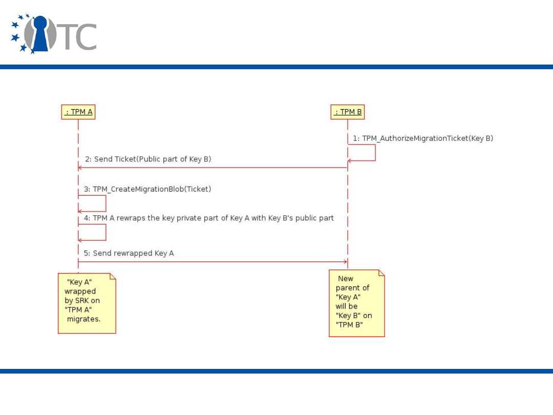
www.opentc.net
29 May 2007
96
Basic Key Migration

www.opentc.net
29 May 2007
97
TSPI – Migrate Key(2)
TSS_HKEY hKeyToMigrate, hKeyToMigrateInto;
TSS_HKEY hMigrationAuthorityKey;
BYTE *MigTicket;
UINT32 TicketLength;
BYTE *randomData;
UINT32 randomLength;
UINT32 migBlobLength;
BYTE *migBlob;
TSS_HTPM hTPM;
TSS_HPOLICY hPolicy, tpmUsagePolicy;
// create and connect to context
// get tpm object
// Load SRK
// take tpm ownership
// create a migratable key in handle hKeytoMigrate

www.opentc.net
29 May 2007
98
TSPI – Migrate Key(3)
result = Tspi_TPM_AuthorizeMigrationTicket( hTPM,
hMigrationAuthorityKey, TSS_MS_MIGRATE,
&TicketLength, &MigTicket);
result = Tspi_Key_CreateMigrationBlob(
hKeyToMigrate, hSRK, TicketLength, MigTicket,
&randomLength, &randomData,
&migBlobLength, &migBlob);
result = Tspi_Key_LoadKey(hMigrationAuthorityKey,
hSRK);
result = Tspi_Key_ConvertMigrationBlob(
hKeyToMigrateInto, hMigrationAuthorityKey,
randomLength, randomData, migBlobLength,
migBlob);

www.opentc.net
29 May 2007
99
TSPI - Hash Class Methods
• These methods are used for general purpose
manipulation of message digests and signatures.
– Tspi_Hash_Sign
– Tspi_Hash_VerifySignature
– Tspi_Hash_SetHashValue
– Tspi_Hash_GetHashValue
– Tspi_Hash_UpdateHashValue

www.opentc.net
29 May 2007
100
TSPI – Data Class Methods
• These methods are used to send/receive data where the
TPM is the endpoint of communication.
– Tspi_Data_Bind
– Tspi_Data_Unbind
– Tspi_Data_Seal
– Tspi_Data_Unseal

www.opentc.net
29 May 2007
101
TSPI – Data Sealing
• Sealing means data will be decrypted again if it was
encrypted on the same platform and the current
configuration.
TSS_HKEY
hKey;
BYTE
*rgbDataToSeal = "This is a test. 1 2 3.";
BYTE
rgbPcrValue[20];
TSS_HENCDATA hEncData;
TSS_HPCRS
hPcrComposite;
UINT32
BlobLength;
UINT32
ulDataLength = strlen(rgbDataToSeal);
// create and connect to context
// Load SRK
// create a storage key in handle hKey

www.opentc.net
29 May 2007
102
TSPI – Data Sealing
result = Tspi_Context_CreateObject( hContext,
TSS_OBJECT_TYPE_PCRS,0, &hPcrComposite );
result = Tspi_PcrComposite_SetPcrValue( hPcrComposite, 8, 20,
rgbPcrValue );
result = Tspi_PcrComposite_SetPcrValue( hPcrComposite, 9, 20,
rgbPcrValue );
result = Tspi_Data_Seal( hEncData, hSRK, ulDataLength,
rgbDataToSeal, hPcrComposite );

www.opentc.net
29 May 2007
103
TSPI – PCR Class Methods
• These methods are used to manipulate PCR registers
maintained within the TPM.
– Tspi_PcrComposite_SelectPcrIndex
– Tspi_PcrComosite_SetPcrValue
– Tspi_PcrComposite_GetPcrValue

www.opentc.net
29 May 2007
104
TSPI – Callback Functions
• These callback functions are used by TSPI policy objects
when the calleer preferences dictate different or dynamic
behavior.
– Tspip_CallbackHMACAuth
– Tspip_CallbackXorEnc
– Tspip_CallbackTakeOwnership
– Tspip_CallbackChangeAuthAsym
– Tspicb_CollateIdentity
– Tspicb_ActivateIdentity

www.opentc.net
29 May 2007
105
Trusted GRUB
• TrustedGRUB is an extension of the original GNU GRUB
bootloader. It has been modified to detect and support
the new Trusted Computing functionalities provided by a
Trusted Platform Module (TPM) as specified by the
Trusted Computing Group (TCG).
• The main feature of TrustedGRUB is the possibility to
measure arbitrary files during the boot process and
extend the integrity test results into so called "Platform
Configuration Registers (PCR)" inside TPMs memory.
• http://www.prosec.rub.de/trusted_grub.html

www.opentc.net
29 May 2007
106
Trusted GRUB (2)
• Measurements in Trusted GRUB
– PCR 4 contains MBR information and stage1
– PCR 8 contains bootloader information stage2 part1
– PCR 9 contains bootloader information stage2 part2
– PCR 12 contains all commandline arguments from menu.lst
and those entered in the shell
– PCR 13 contains all files checked via the checkfile-routine
– PCR 14 contains all files which are actually loaded (e.g.,
Linux kernel, initrd, modules...)
www.opentc.net
29 May 2007
108
The information in this document is provided “as is”, and no guarantee or
warranty is given that the information is fit for any particular purpose.
The user thereof uses the information at its sole risk and liability.
The Open-TC project is co-financed by the EC.
If you need further information, please visit our website
www.opentc.net or contact the coordinator:
Technikon Forschungs- und Planungsgesellschaft mbH
Richard-Wagner-Strasse 7, 9500 Villach, AUSTRIA
Tel.
+
43 4242 23355 – 0
Fax.
+
43 4242 23355 – 77
Email coordination@opentc.net
Open_TC EC Contract No: IST-027635

© 2006 Hewlett-Packard Development Company, L.P.
The information contained herein is subject to change without notice
TCG Trusted Computing
Technology
Royal Holloway MSc in
Information Security
January 2007, Egham, UK
Graeme Proudler
Trusted Systems Laboratory, HP Labs, Bristol
UK

2
14 June, 2007
Basic functions
•
Provide evidence that the platform can measure
and record integrity metrics, report integrity
metrics, and protect keys and other small data
− Platform Endorsement
− Platform identity
•
Measure and record integrity metrics
•
Report integrity metrics
•
Protect keys and other small data

3
14 June, 2007
There are multiple Roots of Trust
•
A Root of Trust for Measurement – The
component that can be trusted to reliably
measure and report to the Root of Trust for
Reporting (the TPM) what software executes at
the start of platform boot
•
A Root of Trust for Reporting and a Root of Trust
for Storage (the TPM) – The component that can
be trusted to store and report reliable information
about the platform
•
It is necessary to trust these Roots of Trust in
order for TCG mechanisms to be relied upon
(hence requirement for Conformance and
Certification)
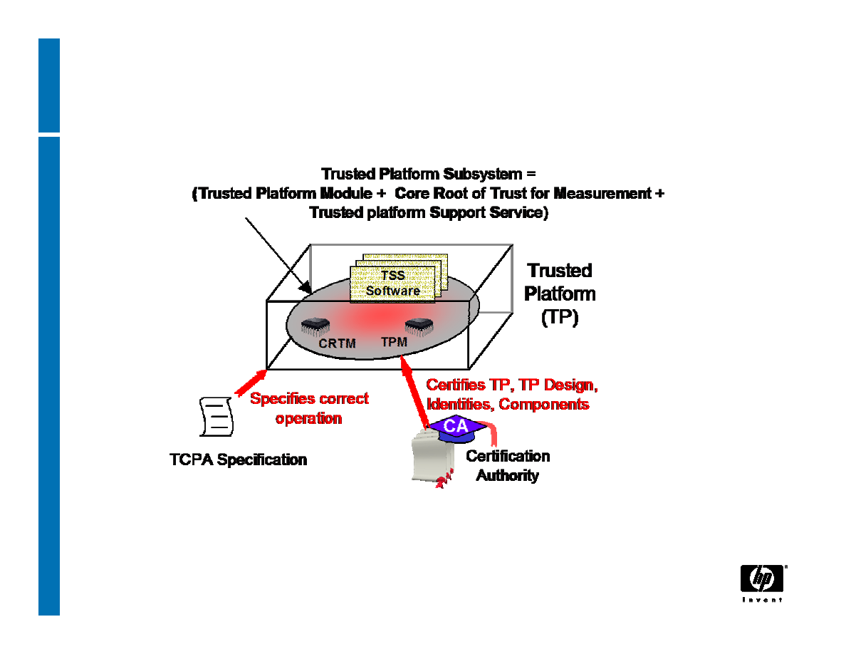
4
14 June, 2007
Trusted Building Block

5
14 June, 2007
Static and Dynamic Roots of Trust for
Measurement
RTM is a function that executes on the platform
when the previous history of the platform can’t
affect the future of the platform
− trusted to properly report to the TPM the first
software/firmware that executes after some sort
of reset
− Static RTM is CPU after platform reset
− Dynamic RTM is CPU after partition reset

6
14 June, 2007
The Core Root of Trust for
Measurement
- CRTM -
• The CRTM is the first piece of code that executes
on a platform at boot time. (eg. BIOS or BIOS
Boot Block in existing platform, or CPU program
on next generation platforms)
−It must be trusted to properly report to the TPM
what is the first software/firmware that executes
after it
−Only entities trusted by those who certify
behaviour can reflash the CRTM
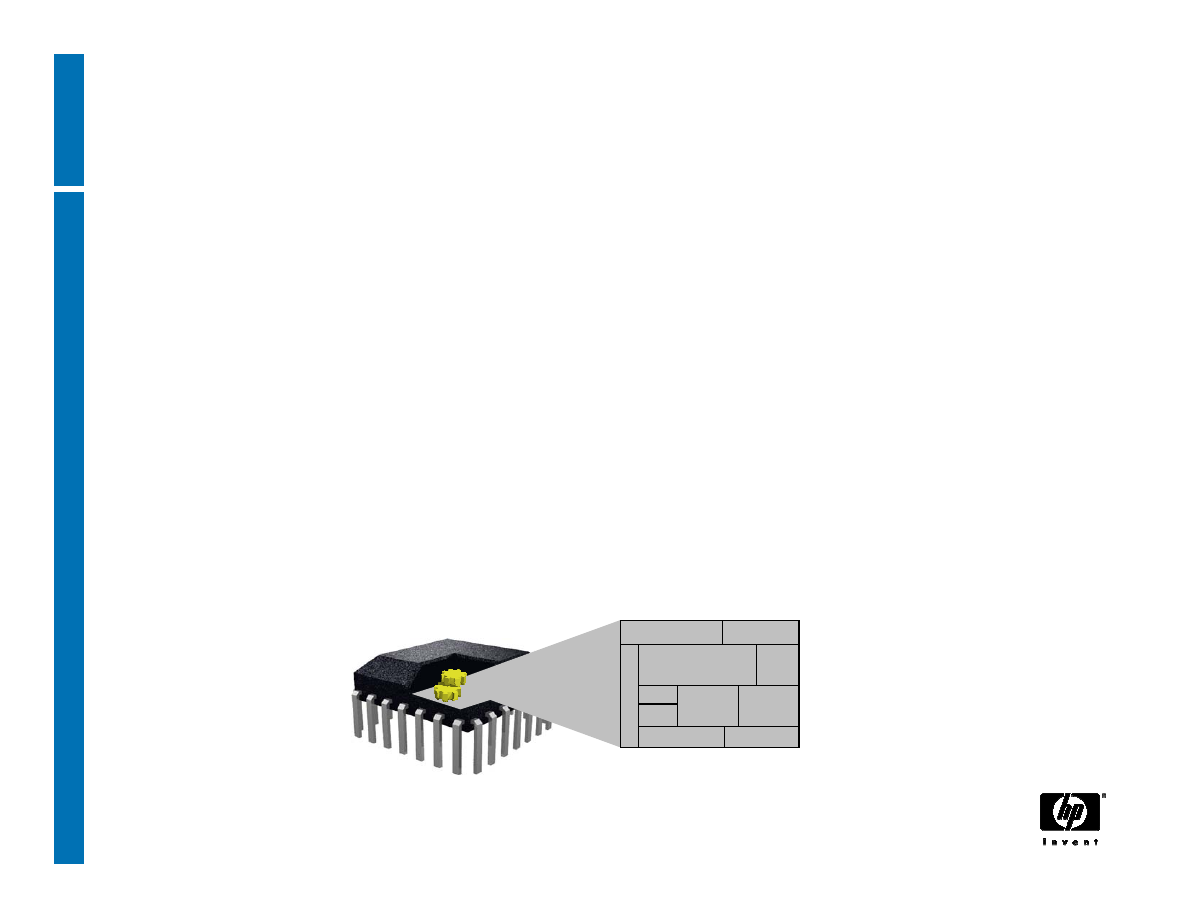
7
14 June, 2007
The Trusted Platform Module
- TPM -
• The TPM is the Root of Trust for Reporting. Think:
smartcard-like security capability embedded into
the platform
• The TPM is trusted to operate as expected
(conforms to the TCG spec)
−The TPM is uniquely bound to a single platform
−TPM functions and storage are isolated from all
other components of the platform (e.g., the CPU)
random number
generation
Non-volatile
Memory
Processor
Memory
asymmetric
key
generation
signing and
encryption
power detection
clock/timer
I/O
HMAC
hash

8
14 June, 2007
Trusted Platform Module
−Protects keys in a platform, even when the
platform is switched off
−Used indirectly to provide evidence that the
platform can provide isolated environments
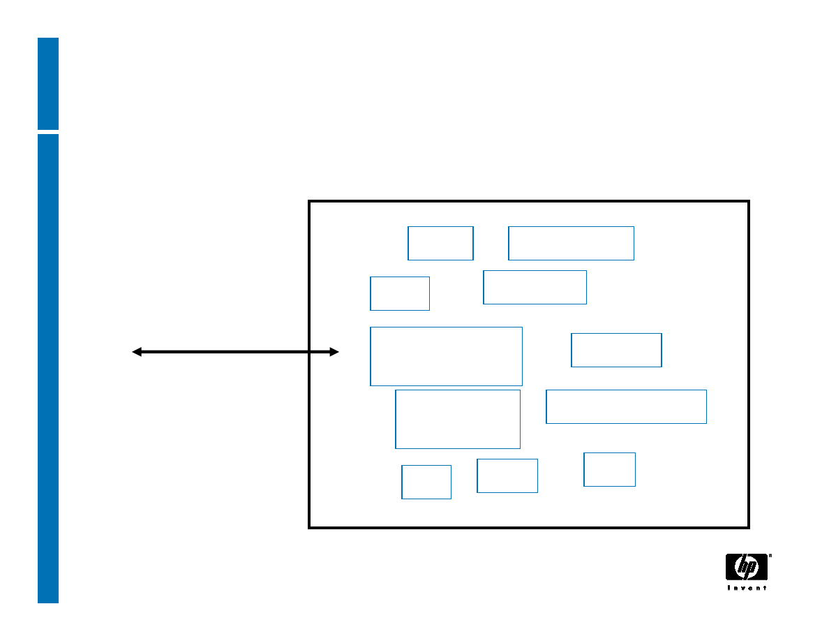
9
14 June, 2007
TPM functions
hash
processor
NV memory
RNG
Asymmetric
key generation
memory
Power detection
Signing and
encryption
I/O
MAC
PCR
command
and command
source

10
14 June, 2007
TPM lifecycle
1. Set:
− disable==FALSE
− ownership==TRUE (redundant flag)
− deactivated==TRUE
2. Execute TPM_takeOwnership to insert Owner’s
Auth value and create Storage Root Key SRK)
3. Set deactivated==FALSE
4. Use the TPM
5. Erase Owner’s Auth value via cryptographic use
of Owner’s Auth or Physical Presence
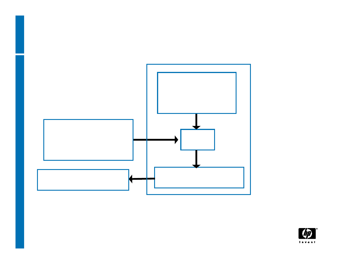
11
14 June, 2007
Creating random numbers
Internal
entropy source
mixer
one-way function
TPM_StirRandom
(entropy)
TPM_GetRandom

12
14 June, 2007
Endorsement Key
•One EK per TPM
• EK is a decrypting key, not a signing key
• used to recognise a platform (can’t be used to
identify a platform)
• Used to
• Assert ownership of a TPM
• Deliver pseudonymous identities to a TPM
13
14 June, 2007
Erasable Endorsement Keys
No EK
installed
EK
installed
erase=
{0:1}
TPM_CreateRevocableEK
(if erase==1)
Physical Presence
+ EKreset passwd
TPM_RevokeTrust
• RevokeTrust clears old TPM “personality” from TPM and
enables generation of new EK that is guaranteed to be private.
• Disadvantage: implicitly invalidates all existing attestation
14
14 June, 2007
TPM Endorsement certificate
String
"TCPA Trusted Platform Module Endorsement"
public Endorsement key
TPM type + TPM security properties
TPME reference
15
14 June, 2007
Platform Certificate
String
"TCPA Trusted Platform Endorsement"
Reference to endorsement credential
Platform type + platform security properties
PE reference
Reference to conformance credential

16
14 June, 2007
Platform Attestation
• TCG provides for a TPM to control “multiple
pseudononymous attestation identities”
• TPM attestation identity does not contain any owner/user
related information
− It is a platform identity, to attest to platform properties
• A TPM uses attestation identities when proving that it is a
genuine (conformant to TCG) TPM, without identifying a
particular TPM
• Identity creation protocol allows choice of any (different)
Certification Authorities (Privacy-CA) to certify each TPM
identity, or use of DAA protocol
− This prevents correlation

17
14 June, 2007
Attestation entities
•
Trusted Platform Module Entity (TPME) vouches that the
Trusted Platform Module (TPM) is genuine by attesting for
the Endorsement key inside the TPM
•
Validation Entity (VE) certifies the values of integrity
measurements that are to be expected when a particular
part of the platform is working properly
•
Conformance Entity (CE) vouches that the design of the
TCPA Subsystem in a class (type) of platform meets the
requirements of the TCPA specification
•
Platform Entity (PE) vouches for a platform containing a
specific TPM
•
Privacy Certification Authority (Privacy-CA; P-CA) attests
that an ID belongs to a TP
•
DAA issuer provides DAA credentials for a TPM
18
14 June, 2007
Platform Identity Certificate
String
"TCPA TPM Identity"
TPM identity chosen name
Platform type + platform security properties
Privacy-CA reference
String
TPM type + TPM security properties
TPM identity public key
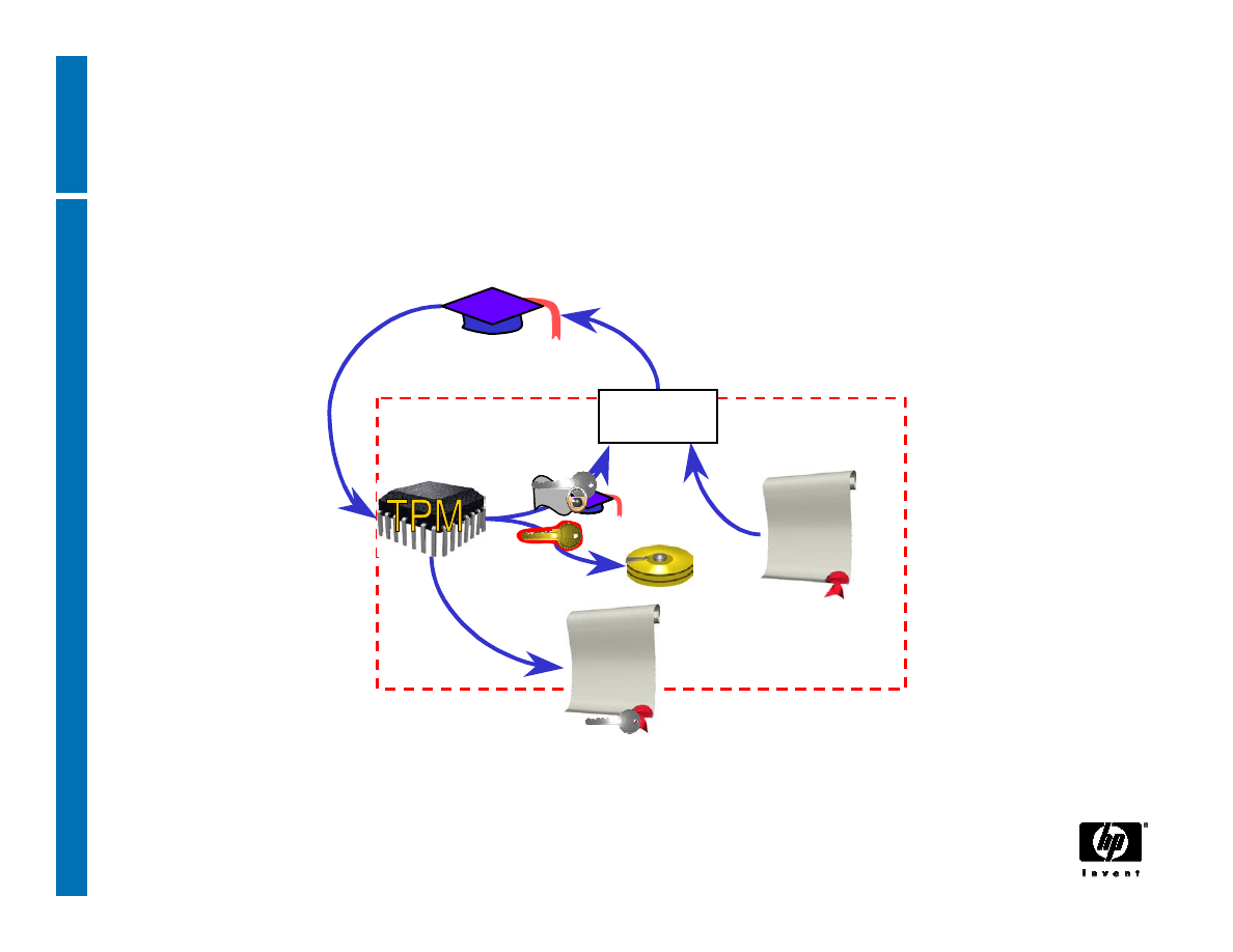
19
14 June, 2007
TPM Identity creation: Privacy-CA (1)
Certificates
Under Owner’s
control for Privacy
Identity
Certificate
Identity-binding
Identity
Certification Authority
Owner
Owner
CA
ABC
ABC
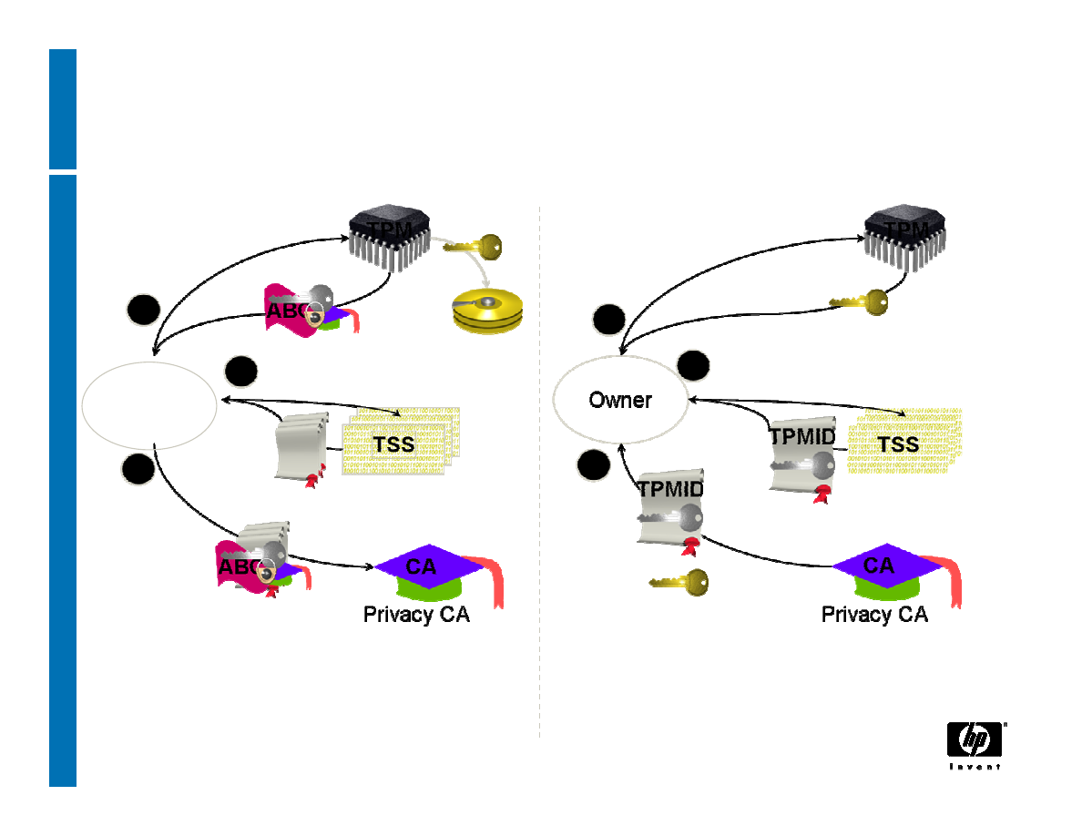
20
14 June, 2007
TPM Identity creation: Privacy CA (2)
Owner
TPM_MakeIdentity
TPM_ActivateIdentity
TSS_CollateIdentityRequest
Contact
Privacy-CA
TSS_Recover_TPM_identity
ID Binding
ID Key
Credentials
Encrypted
ID Proof
Session Key
Encrypted
TPM_identity_credentials
TPM_identity_credentials
1 – Request ID Certificate
2 – Retrieve ID Certificate

21
14 June, 2007
TPM Identity creation: DAA (1)
•
Direct Anonymous Attestation - DAA
•
A zero-knowledge method to prove that a platform
has attestation without revealing attestation
information
•
Introduced because of concerns about privacy,
and viability and trustworthiness of Privacy-CA
•
Provides a spectrum of pseudonymity because
need to audit and revoke rogue platforms
•
Allows revocation of compromised TPM keys

22
14 June, 2007
TPM Identity creation: DAA (2)
•
A verifier doesn’t see specific attestation
information issued to a platform, but believes the
platform has attestation and (optionally) can tell
whether the platform has previously communicated
with the verifier
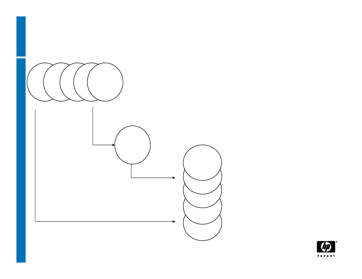
23
14 June, 2007
DAA: infrastructure
Arbitrary number of DAA issuers:
any credible entity (almost certainly
including the platform OEM)
Arbitrary number of
DAA verifiers
DAA issuer credentials
TPM_DAAsign
TPM_DAAjoin
TPM
verifier
issuer
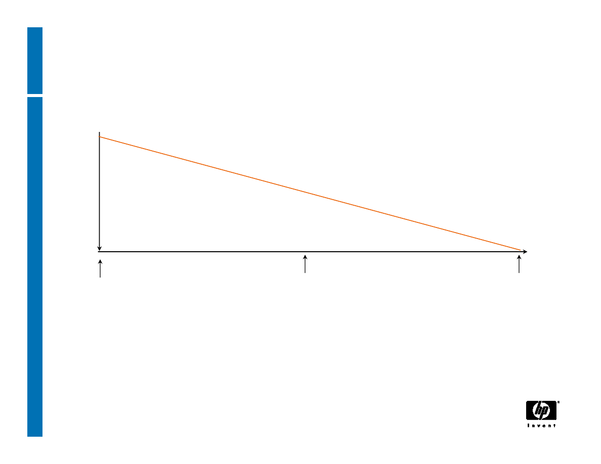
24
14 June, 2007
DAA: audit and privacy
Audit
trail
nonce ID
long-term ID
mid-term ID
Audit capabilities depend on selected DAA “name”
parameter
•Even long-term IDs provide (some) privacy
0
1
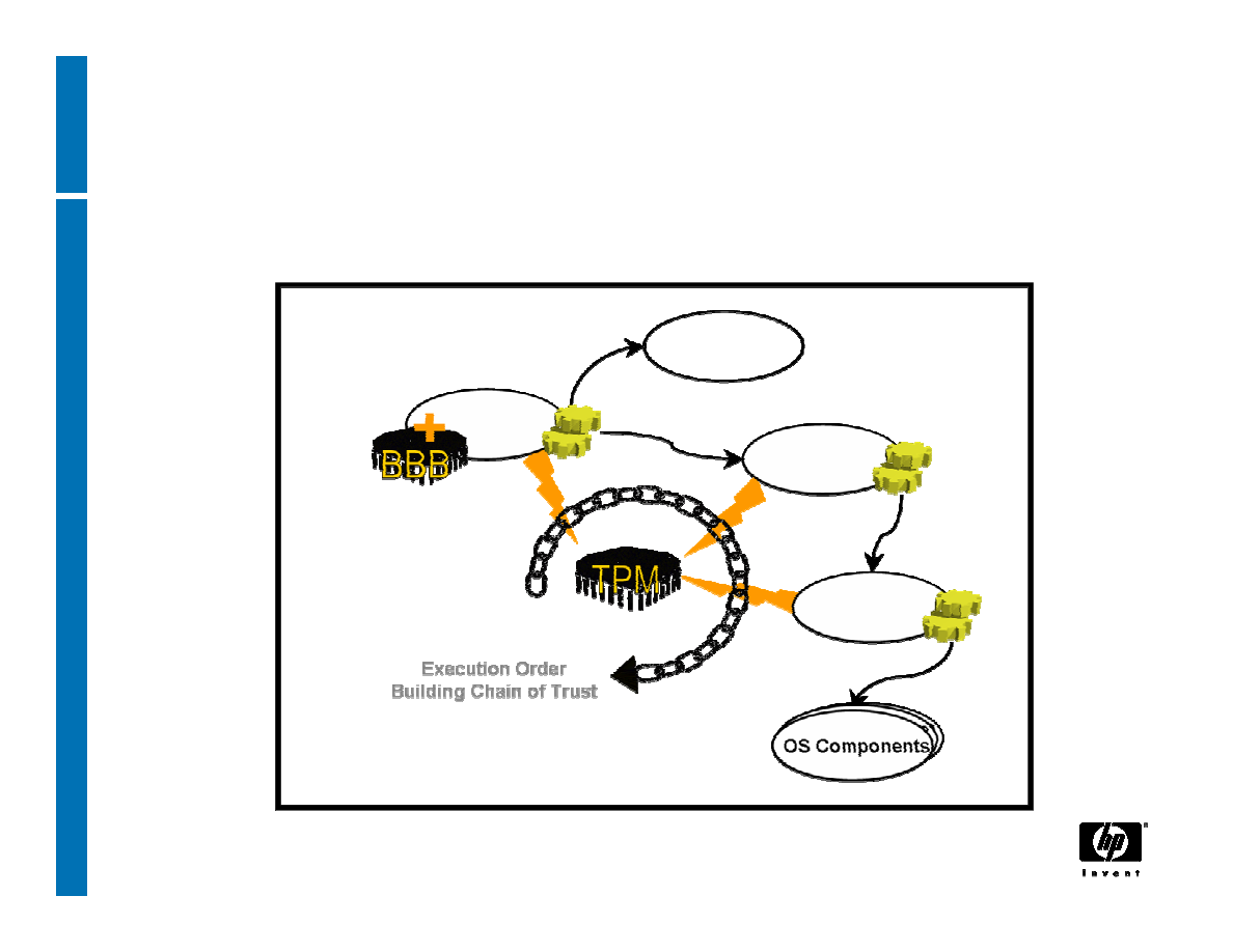
25
14 June, 2007
Authenticated Boot
BIOS
Measures
ROMs
Measures
Measures
Measures
Sends Value
Sends Value
Sends Value
Trusted PC Components
OS Loader
OS
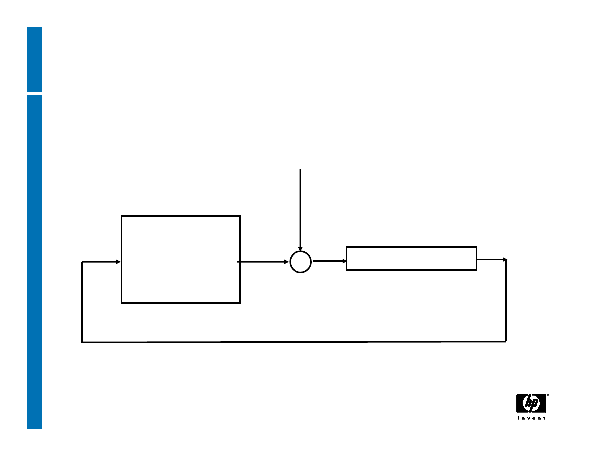
26
14 June, 2007
TPM Extend
+
Platform
Configuration
Register
Hash algorithm
input
append

27
14 June, 2007
Reporting integrity
• Measurements reported to the TPM during (and
after) the boot process cannot be removed or
deleted until reboot
• The TPM will use an attestation identity to sign
the integrity report
• The recipient of integrity information can evaluate
trustworthiness of the information based on the
certificate of attestation identity
Trust that the TPM is a genuine TPM on a
genuine Trusted Platform

28
14 June, 2007
Using integrity reports
• The recipient of reported information needs
“signed certificates” that prove that a given
measurement represents a known piece of code
−Cert(BIOS v1.2 has hash value of H)
−Cert(CorpIT config, combined hash value)
• The recipient can verify these Integrity Metrics
Certificates and compare certified metrics to
reported metrics
Trust that the reported metrics correspond to
certified software
Trusting the reported software is sole responsibility
of the recipient’s policy, for his application context

29
14 June, 2007
Protected Storage
• Not a generic bulk encryption device – no export
control problem
• Cryptographic keys can be created and protected
by the TPM
• Data/keys can be encrypted such that they can
only be decrypted using this TPM
• A specific software configuration can also be
specified, that will be required for the TPM to
allow data to be decrypted, or keys to be used
This is called “sealing”: parameters define the
Integrity Metrics to which the data should be
sealed
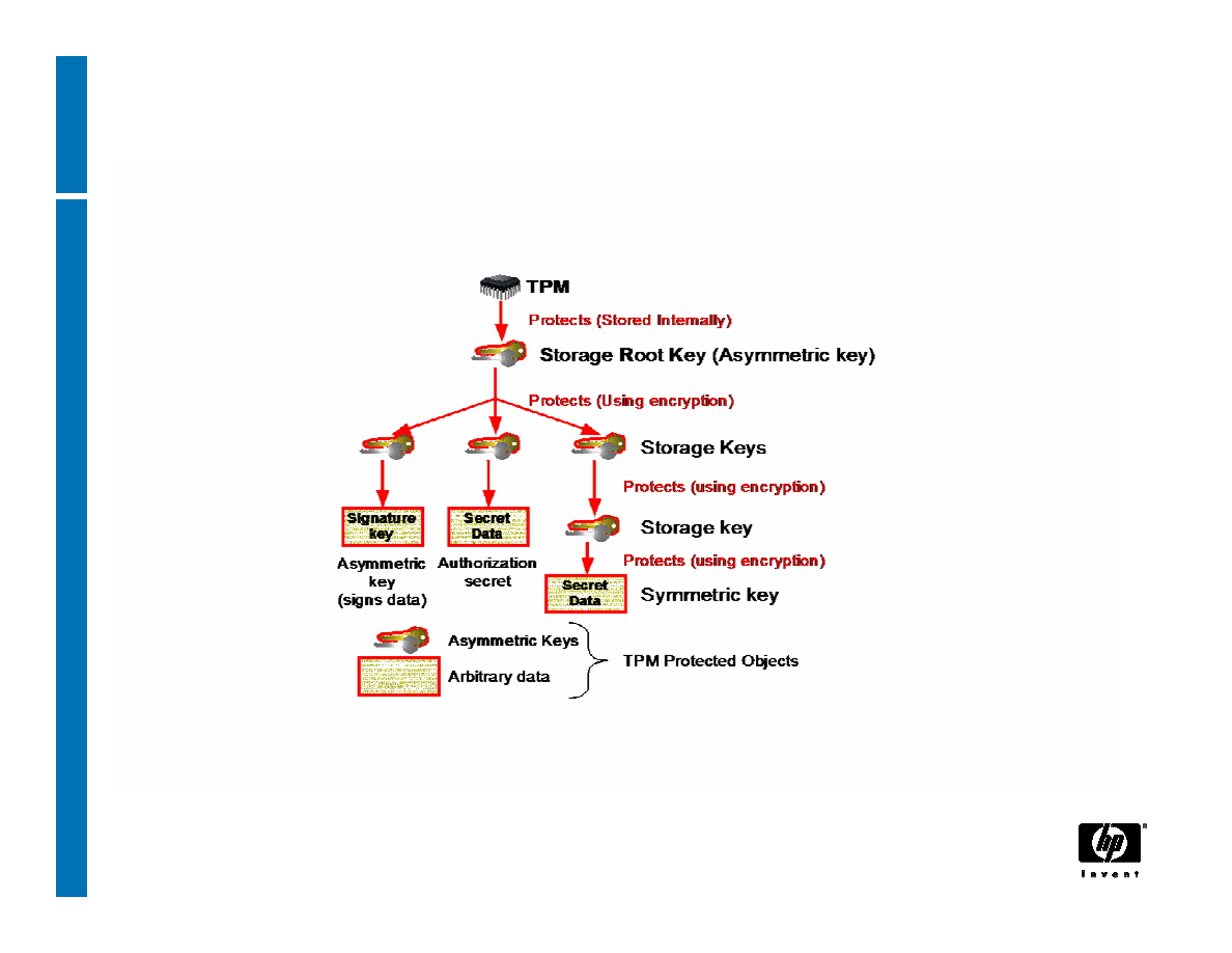
30
14 June, 2007
Protected Storage Hierarchy
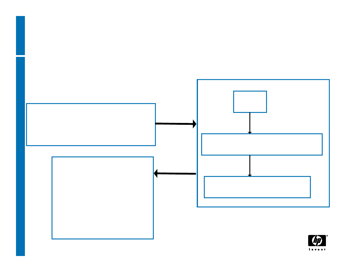
31
14 June, 2007
Creating keys
RNG
asymm key generation
structure generation
TPM_CreateWrapKey
Parent, key type,
authValue, releasePCRs
Public parameters
(plain text)
private parameters
(encrypted)
32
14 June, 2007
Encrypting data
TPM_Seal states the password and PCR values that must
be used to recover the data with TPM_Unseal
keyHandle
encAuth
pcrInfo
inData
sealedData
PCRsAtCreatio
n
PCRsAtReleas
e
input
output
33
14 June, 2007
Decrypting sealed data
TPM_Unseal
keyHandle
BLOB
Check that PCR values
in BLOB match current
PCR values
data
PCRsAtCreatio
n
34
14 June, 2007
Decrypting normal encrypted data
TPM_UnBind
keyHandle
BLOB
data
35
14 June, 2007
signing data
TPM_sign
keyHandle
Data
Signature scheme
signature value