D05.5 Design and Concept of a
Trusted Virtual Datacenter
Project number
IST-027635
Project acronym
Open_TC
Project title
Open Trusted Computing
Deliverable type
Report
Deliverable reference number
IST-027635/D05.5/FINAL
Deliverable title
Design and Concept of a Trusted Virtual
Datacenter
WP contributing to the deliverable
WP05
Due date
Oct 2008 - M36
Actual submission date
November 21
st
, 2008
Responsible Organisation
IBM
Authors
Contributors listed alphabetically by
organisation:
CUCL (Theodore Hong, Eric John, Derek
Murray); HP (Serdar Cabuk, David Plaquin);
IBM (Bernhard Jansen, HariGovind V.
Ramasamy, Matthias Schunter); RUB (Yacine
Gasmi, Ahmad-Reza Sadeghi, Patrick Stewin,
Martin Unger); POL (Gianluca Ramunno,
Davide Vernizzi)
Abstract
This report describes the key concepts of the
OpenTC Secure Virtual Datacenter.
Keywords
Virtual Datacenter, Proof-of-Concept
Dissemination level
Public
Revision
FINAL
Instrument
IP
Start date of the
project
1
st
November 2005
Thematic Priority
IST
Duration
42 months

A
BSTRACT
This report describes the key concepts of the OpenTC Secure Virtual Datacenter.
It is structured into two parts.
Part I surveys the key concepts underlying the 2009 proof of concept “Trusted
Virtual Datacenter” that demonstrates how to securely virtualize a datacenter while
providing verifiable security.
Part II describes selected components and future directions in more detail.
A
CKNOWLEDGMENTS
The following people were the main contributors to this report (alphabetically
by organization): Theodore Hong, Eric John, Derek Murray (CUCL); Serdar
Cabuk, David Plaquin (HP); Bernhard Jansen, HariGovind V. Ramasamy, Matthias
Schunter (IBM); Yacine Gasmi (RUB), Ahmad-Reza Sadeghi (RUB), Patrick
Stewin (RUB), Martin Unger (RUB); Gianluca Ramunno (Polito), Davide Vernizzi
(Polito). We would like to thank our reviewer Peter Lipp from IAIK Graz for sub-
stantial feedback.
Furthermore, we would like to thank the other members of the OpenTC project
for helpful discussions and valuable contributions to the research that is docu-
mented in this report.We would like to thank in particular Cataldo Basile from
Politecnico di Torino, Italy, for valuable input on the policy framework.
This work has been partially funded by the European Commission as part of
the OpenTC project [Ope08a] (ref. nr. 027635). It is the work of the authors alone
and may not reflect the opinion of the entire project.
2

4
OpenTC D05.5 – Design and Concept of a Trusted Virtual Datacenter
III
Conclusion
86
Bibliography
89
OpenTC Document D05.5/V01 – Final R7343/2008/11/11/OpenTC Public (PU)

Part I
Main Concepts of the OpenTC
Trusted Virtual Datacenter
5

Chapter 1
Introduction and Outline
1.1
Introduction
Hardware virtualization is enjoying a resurgence of interest fueled in part by its
cost-saving potential. By allowing multiple virtual machines to be hosted on a
single physical server, virtualization helps improve server utilization, reduce man-
agement and power costs, and control the problem of server sprawl.
A prominent example in this context is data centers.
The infrastructure
provider, who owns, runs, and manages the data center, can transfer the cost sav-
ings to its customers or outsourcing companies, whose virtual infrastructures are
hosted on the data center’s physical resources. A large number of the companies
that outsource their operations are small and medium businesses or SMBs, which
cannot afford the costs of a dedicated data center in which all the data center’s
resources are used to host a single company’s IT infrastructure. Hence, the IT in-
frastructure belonging to multiple SMBs may be hosted inside the same data center
facility. Today, even in such “shared” data centers, each run on distinct physical
resources and there is no resource sharing among various customers. In this so-
called physical cages model, the customers are physically isolated from each other
in the same data center.
Limited trust in the security of virtual datacenters is one major reason for cus-
tomers not sharing physical resources. Since management is usually performed
manually, administrative errors are commonplace. While this may lead to down-
times in virtual datacenters used by a single customer, it can lead to information
leakages to competitors if the datacenter is shared. Furthermore, multiple organi-
zations will only allow sharing of physical resources if they can trust that security
incidents cannot spread across the isolation boundary separating two customers.
Security Objectives
Our main security objective is to provide isolation among
different domains that is comparable
1
with the isolation obtained by providing one
infrastructure for each customer. In particular, we require a security architecture
1
Note that unlike physical isolation, we do not solve the problem of covert channels.
6
CHAPTER 1. INTRODUCTION AND OUTLINE
7
that protects those system components that provide the required isolation or allow
to verifiably reason about their trustworthiness of and also of any peer endpoint
(local or remote) with a domain, i.e., whether they conforms to the underlying
security policy.
We achieve this by grouping VMs dispersed across multiple physical resources
into a virtual zone in which customer-specified security requirements are automat-
ically enforced. Even if VMs are migrated (say, for load-balancing purposes) the
logical topology reflected by the virtual domain should remain unchanged. We
deploy Trusted Computing (TC) functionality to determine the trustworthiness (as-
sure the integrity) of the policy enforcement components.
Such a model would provide better flexibility, adaptability, cost savings than
today’s physical cages model while still providing the main security guarantees
required for applications such as datacenters.
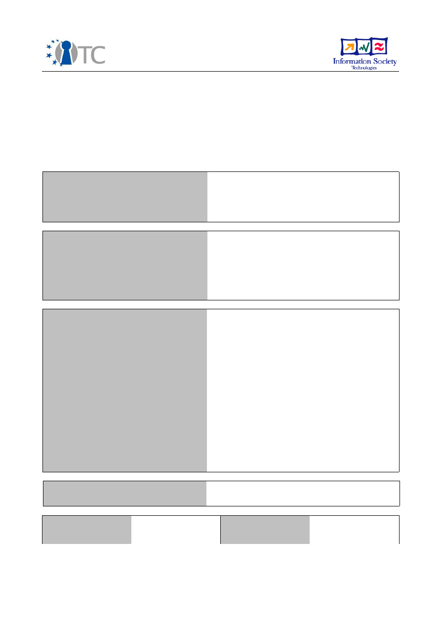
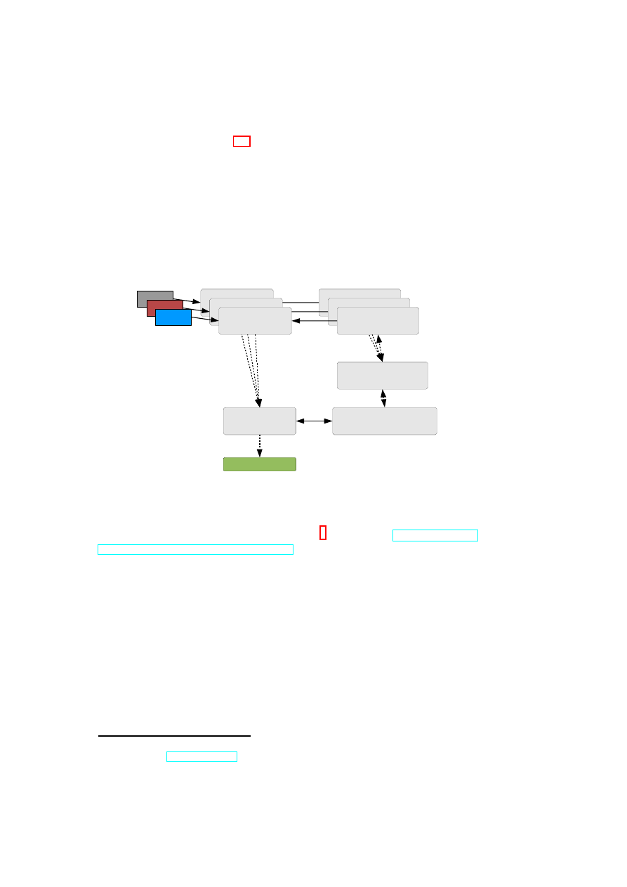
Hardware Platform
Hypervisor
Security Services
VM
A1
VM
A2
VM
A3
VM
A4
TVD1
Master
TVD1
Master
TVD1
Master
Proxy1
…
Proxy2
Hardware Platform
Hypervisor
Security Services
VM
B1
VM
B2
VM
B3
VM
B4
Proxy1
…
Proxy2
Figure 1.1: TVD Architecture: High-Level Overview.
Contribution
In this deliverable, we provide a blueprint for realizing a logical
cages model, in particular for virtualized data centers, based on a concept called
Trusted Virtual Domains or TVDs [BGJ
+
05]. Based on previous work, we de-
scribe a security management framework that helps to realize the abstraction of
TVDs by guaranteeing reliable isolation and flow control between domain bound-
aries. Our framework employs networking and storage virtualization technolo-
gies as well as Trusted Computing for policy verification. Our main contributions
are (1) combining these technologies to realize TVDs and (2) orchestrating them
through a management framework that automatically enforces isolation among dif-
ferent zones. In particular, our solution aims at automating the verification, instan-
tiation and deployment of the appropriate security mechanisms and virtualization
OpenTC Document D05.5/V01 – Final R7343/2008/11/11/OpenTC Public (PU)

8
OpenTC D05.5 – Design and Concept of a Trusted Virtual Datacenter
technologies based on an input security model, which specifies the required level
of isolation and permitted information flows.
1.2
Outline of this Report
This deliverable is structured into three parts.
Part I introduces the objectives and main concepts of a trusted virtual datacen-
ter. This includes the the high-level architecture documented in Chapter 2 and the
policy enforcement, refinement, and management in Chapter 3.
Part II then documents details of two building blocks, namely networking and
dependability. Chapter 4 describes our revised and detailed description of auto-
mated provisioning of virtual networks and their security elements such as fire-
walls and Virtual Private Networks (VPN). Chapter 5 investigates how to increase
the dependability of datacenters in order to allow virtualization of mission-critical
applications. This chapter concludes by proposing a dependability-enhanced archi-
tecture for the Xen hypervisor where different virtual machines monitor each other.
Whenever failures are detected, the machines are then dynamically rejuvenated to
retain service.
Part III concludes this report, contains an appendix with an extensive bibliog-
raphy of related work.
OpenTC Document D05.5/V01 – Final R7343/2008/11/11/OpenTC Public (PU)

Chapter 2
Secure Virtualized Datacenters
We now outline the OpenTC 2009 proof of concept prototype and its main archi-
tectural elements.
2.1
Objectives & Proof-of-concept Scenario
2.1.1
Main Objectives
We have built a virtual datacenter that should be comparable with a consolidated
and simplified version of today’s datacenters. Like today, a datacenter will e used
by many customers. As a consequence, customer isolation is of paramount impor-
tance.
The next important observation is that customers are usually transitioned from
their own legacy datacenters into a shared datacenter. As a consequence, each
customer usually has a legacy way of managing its datacenter. This legacy way
should be supported by the new datacenter. Ideally, whatever hard- and software
as well as management infrastructure a customer had should be virtualized and
supported by the new virtual datacenter.
2.1.2
Virtual Datacenter Scenario
The scenario we want to demonstrate has multiple sub-scenarios with increasing
complexity:
“Physical Systems” Management The first scenario is the provisioning of for-
merly physical systems. The scenario we build is a customer who boots a
server and installs this server from the network. For this scenario, virtualiza-
tion should be transparent.
Hosting Media Services The second scenario is to use the datacenter to host me-
dia services. The goal is to allow outsiders to play media iff their platform
has been validated and deemed trustworthy.
9

10
OpenTC D05.5 – Design and Concept of a Trusted Virtual Datacenter
Virtual Systems Management The third scenario aims at virtualizing virtual sys-
tems. The key idea is that today, customers will have virtualized systems
such as Xen that need to be embedded and managed as a part of our virtual
datacenter.
We do this by migrating a Xen installation into our datacenter and then com-
puting a view of the datacenter that corresponds to the former Xen installa-
tion.
2.2
High-level Architecture
We now describe the architecture of our demonstrator. This architecture has several
components, namely hosts, networks, storage, virtual machines, and software.
2.2.1
Network Architecture
We use the trusted virtual domain model to isolate different networks. In this model
each domain is isolated from other domains while being only permitted to commu-
nicate via well-defined gateways.
In order to structure the demonstrator, we have defined the following domains
(see Figure 2.1):
Customer application zone This domain constitutes a network of a given cus-
tomer. It transports the application traffic of a given customer. Ordinary
users can access this network.
Customer management zone This domain is the management network of a given
customer. It is used for provisioning of virtual machines, monitoring ma-
chines, and management of application zones of this customer. Administra-
tors of each customer can access the corresponding management zone.
Datacenter management zone This network is used by the datacenter adminis-
trators to manage the overall datacenter. This includes setting up new do-
mains, assigning resources, or removing domains. This domain is also used
for management communication between the different domains.
Demilitarized Zone The DMZ allows customers to connect to the Internet and
allows outsiders to establish connections to a TVD. The former is done by
establishing gateway machines that connect to the internal zone and DMZ.
The latter is achieved by TVD proxy factories connecting to the DMZ.
Storage Area Network The storage area network provides virtual storage to all
physical hosts in a datacenter. The management components can then con-
nect selected storage unites to given virtual machines.
OpenTC Document D05.5/V01 – Final R7343/2008/11/11/OpenTC Public (PU)
CHAPTER 2. SECURE VIRTUALIZED DATACENTERS
11
Cust. 1-A
Cust. 1-B
Cust. 2-A
Cust. 2-B
Cust 2 Mgmt
Cust 1 Mgmt
Datacenter Mgmt
Figure 2.1: Trusted Virtual Domains of a Virtual Datacenter
These network allows clear isolation of different customers while providing a
backbone management network for the TVDC infrastructure to communicate.
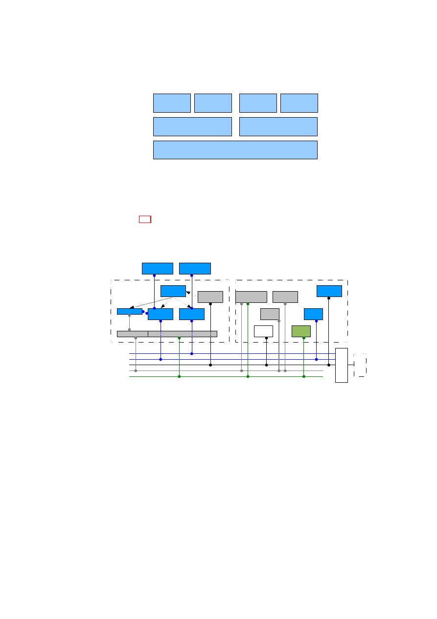
Figure 2.2 depicts the details of the networking for a single user-level TVD.
It is important to note that the datacenter hosts are booted from the network us-
ing the Preboot eXecution Environment (PXE). This allows the administrators to
seamlessly add and remove physical hosts.
VDC
SAN
DMZ
TVDusr
TVDmgn
TVDproxy
Factory
TVDproxy
vSwitch
(mgnt.)
vSwitch
(user)
XenAPI
APIfilter
Xen
DC Host Platform
TVD
Master
F
ire
w
a
ll
In
te
rn
e
t
DHCP
Server
PXEboot
Server
DC infrastructure components
DNS
Server
NFS
Server
NFS
Server
TVD mgnt.
Server VM
TVD Guest
VM
VDC mgnt.
Server
Figure 2.2: Networking Details of a Virtual Datacenter
2.2.2
Multi-Tenant Management
An important goal of our prototype is to enable heterogeneous management. This
means that each customer should be able to use arbitrary existing management
tools to manage their domains: While the datacenter operator uses given software
to assign resources quotas to each customer, the respective customer can then use
his existing management tools to use these resources to build virtual machines on
assigned hosts.
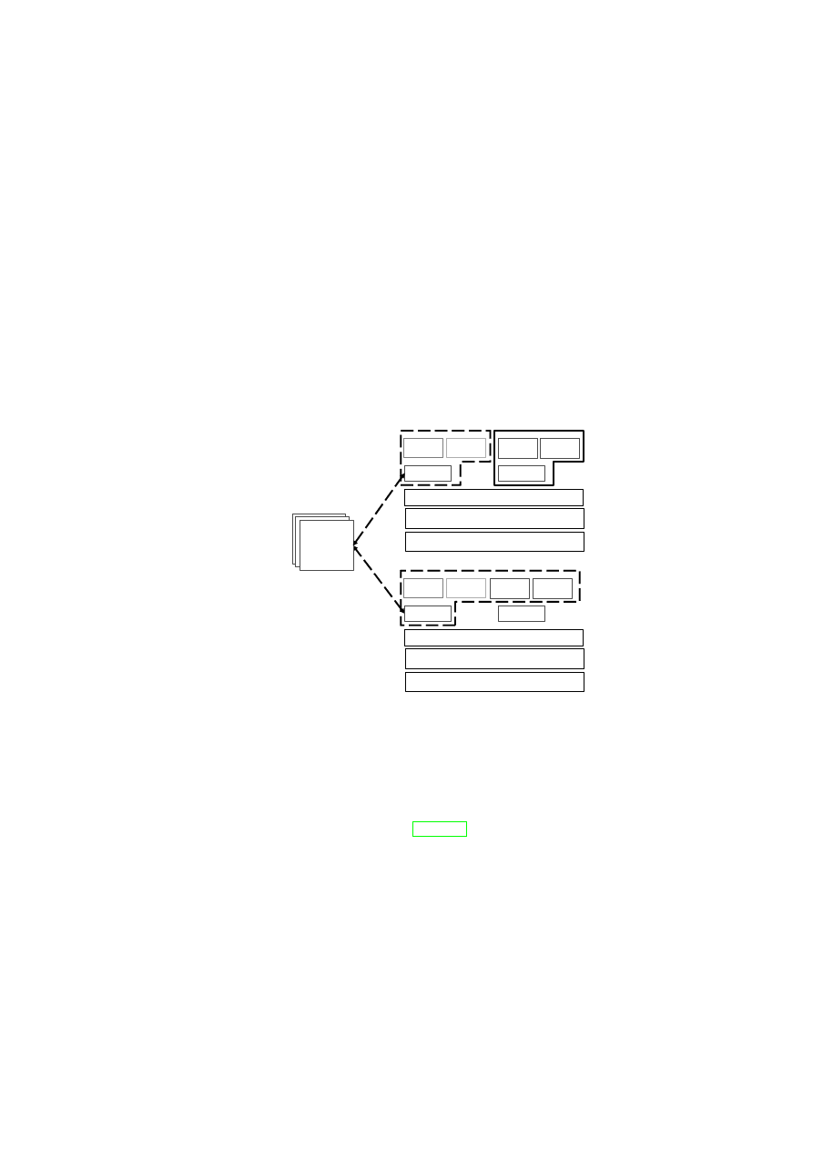
We implement this multi-tenant concept by providing filtered instances of the
XenAPI to individual customers while providing the complete XenAPIs only to the
datacenter operator.
OpenTC Document D05.5/V01 – Final R7343/2008/11/11/OpenTC Public (PU)
12
OpenTC D05.5 – Design and Concept of a Trusted Virtual Datacenter
This is depicted in Figure 2.3: For each customer, a XenAPI filter component is
providing the corresponding filtered XenAPI service to the management network
of the given customer. The basic idea is that the filter obtains the list of VMs
that belong to a given customer and strips all other machines from the returned
information. Similarly, other elements (storage/network) that do not belong to this
customer are stripped.
The XenAPI filter then forwards commands to the internal XenAPI provider.
This provider in turn forwards non-security commands to the existing XenAPI pro-
vided by
xend
while forwarding security extensions to the OpenTC compartment
manager.
API-TVDfilter
(limit visibility of resrcs.)
IF on
Mgnt. net
IF on
Mgnt. net
TVD Proxy
(Enforcing TVD policies,
controlling vNet)
TVD Proxy
(Enforcing TVD policies,
controlling vNet)
API-TVDfilter
(limit visibility of resrcs.)
Compartment Manager
(starting/stopping of
SecServ managed VMs)
TVD Proxy
(Enforcing TVD policies,
controlling vNet)
XenAPI (Xend)
API-basefilter
(intercept VM commands)
API-TVDfilter
(limit visibility of resrcs.)
TVD Proxy Factory
(spawning & directory of proxies)
[VM uuids]
VM.start
VM.stop
VM.destroy
IF on
Mgnt. net
Figure 2.3: Enabling Multi-Tenant by Filtering the XenAPI
Overall this approach allows customers to run any XenAPI-based manage-
ment software. By using the XenAPI-based CIM
1
provider from
http://wiki.
xensource.com/xenwiki/XenCim
, customers can furthermore use any ex-
isting CIM-based management tool to manage their domains.
Similarly, the datacenter operator can directly access the underlying XenAPI
to manage the overall datacenter.
1
This refers to the DMTF System Virtualization, Partitioning, and Clustering Working Group
(SVPC WG). See
www.dmtf.org
.
OpenTC Document D05.5/V01 – Final R7343/2008/11/11/OpenTC Public (PU)

Chapter 3
Policy Enforcement for Virtual
Datacenters
Serdar Cabuk, Chris I. Dalton, Dirk Kuhlmann (HP) Konrad Eriksson,
HariGovind V. Ramasamy, Matthias Schunter (IBM), Gianluca Ramunno (POL),
Ahmad-Reza Sadeghi, Christian Stüble(RUB)
In this chapter wee describe a security management framework that helps re-
alize the abstraction of TVDs by guaranteeing reliable isolation and flow control
between domain boundaries.
After introducing the key concepts such as Trusted Virtual Domains, we ex-
plain the security policies that are enforced in a virtual datacenter in Section 3.1.
The key idea is that the datacenter management can declare a inter-TVD policy
that defines how customers are isolated. Each customer (or domain of a customer)
can then define a intra-TVD security policy that defines how its internal security
is handled. Both policies hold for all resources and can subsequently be refined.
In Section 3.2 we then discuss how these policies are enforced. For enforcement
we focus on the two most important resources that are potentially shared. The key
idea is to provide virtual networks and storage that is assigned to a given domain
and where access by other domains is restricted.
3.1
Security Policies for Virtual Data Centers
Data centers provide computing and storage services to multiple customers.
Customers are ideally given dedicated resources such as storage and physical ma-
chines. Resources such as the Internet connection, however, may be shared be-
tween multiple customers. Each customer has a set of security requirements and
may often specify which security mechanisms must be used to satisfy these require-
ments. For example, different customers may specify different anti-virus software
to be used for their VMs and different virus scanning intervals.
To model and implement these heterogeneous requirements, we introduce a
domain-based security model for enforcing unified security policies in virtualized
13

14
OpenTC D05.5 – Design and Concept of a Trusted Virtual Datacenter
data centers. We focus on isolation policies that mimic physical separation of data
center customers. Our goal is to logically separate customer networks, storage,
VMs, users, and other virtual devices. The core idea is to use this isolation as a
foundation for guaranteeing desired security properties within each virtual domain
while managing shared services under mutually agreed policies.
3.1.1
High-level Policy Model
Our security model is based on TVDs [BGJ
+
05], which isolate their resources from
resources of other TVDs. In the following, we distinguish between the following
resource types:
Virtual Processing Elements: Virtual Processing Elements (VPE) are active ele-
ments (subjects), such as physical or virtual machines, that can be member
of one or more TVDs.
Virtual Infrastructure Elements: Virtual Infrastructure Elements (VIE) are pas-
sive elements (objects), such as physical or virtual disks, that can be member
of one or more TVDs.
Note that computing platforms that host VMs but are not directly member of a TVD
are not considered as VPEs. Moreover, the security model includes two high-level
policies defining the security objectives that must be provided by the underlying
infrastructure:
Inter-TVD Policy: By default, each TVD is isolated from the “rest of the world”.
The high-level information-exchange policy defines whether and how infor-
mation can be exchanged with other TVDs. If no information exchange with
other TVDs is permitted, no resources can be shared unless the data-center
operator can guarantee that these resources guarantee isolation. If flow is in
principle allowed, sub-policies further qualify the exact flow control policy
for the individual resources.
Intra-TVD Policy: Domain policies allow domain owners (e.g., customers) to
define the security objectives within their own TVDs. Examples of such
policies include how the internal communication is to be protected and un-
der what conditions resources (e.g., storage, machines) can join a particular
TVD.
3.1.2
Security Objectives and Policy Enforcement Points
Policies are enforced across different resources in the TVD infrastructure (see Fig-
ure 3.1). The basis of all policies is isolation at the boundary of each TVD.
OpenTC Document D05.5/V01 – Final R7343/2008/11/11/OpenTC Public (PU)
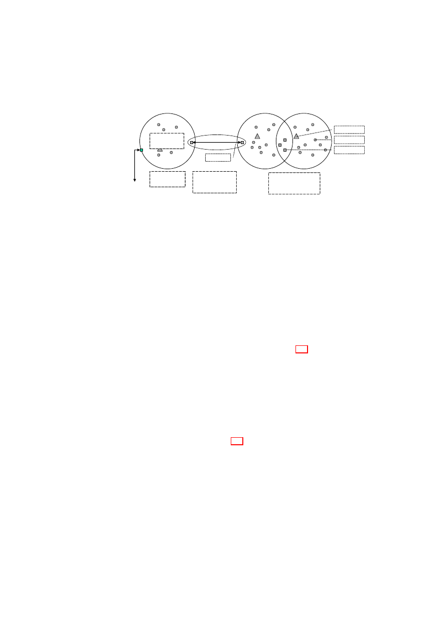
CHAPTER 3. POLICY ENFORCEMENT FOR VIRTUAL DATACENTERS
15
TVD A
TVD B
Internet
Membership
Constraints
Flow
enforcement
by two gateways
Isolation
enforcement
TVD C
Flow
enforcement
by shared machines
TVD AB
Gateway
Server
Clients
Gateways
Machine Types:
Figure 3.1: Types of TVD Policy Enforcement.
By default, each resource is associated with a single domain. This achieves a
basic level of isolation. If an information flow between TVDs is allowed, resources
can also be member of different TVDs. For example, a TVD can allow certain types
of resources on certain hosts to provide services also to other domains. Each TVD
defines rules regarding in-bound and out-bound information flow for restricting
communication with the outside world. The underlying policy-enforcement infras-
tructure then has to ensure that only resources trusted by all TVDs are shared.
Architecturally, there are two ways of enforcing such rules, depending on the
trust between the TVDs. The first method involves two shared resources connected
by an intermediate domain. In this method, each TVD enforces its side of the flow
control by means of its own shared resource. An example of this type of connection
is the one that exists between TVD A and TVD B in Figure 3.1. This method is used
when the trust level between TVD A and TVD B is low, and the two cannot agree
on a shared resource that is mutually trusted. The shared resource in TVD A will
enforce TVD A’s policies regarding in-bound traffic from TVD B, even if the shared
resource in TVD B does not enforce TVD B’s policies regarding out-bound traffic.
The shared resources can be thought of being a part of a “neutral” TVD (TVD AB)
with its own set of membership requirements.
The second method that requires
shared trust is to establish one or more shared resources that are accessed from
both TVDs while allowing controlled information flow. This mechanism is used
between TVD B and TVD C in Figure 3.1.
Security within a domain is finally obtained by defining and enforcing member-
ship requirements that resources have to satisfy prior to being admitted to the TVD
and for retaining the membership. This may also include special requirements for
different machine types: Because, for example, shared resources play a key role in
restricting information flow between TVDs, the software on those machines may
be subject to additional integrity verification as compared to the software on regular
VPEs.
Flow control policies define the allowed traffic flow between two domains and
how the domains should be protected. Membership policies define domain-internal
OpenTC Document D05.5/V01 – Final R7343/2008/11/11/OpenTC Public (PU)

16
OpenTC D05.5 – Design and Concept of a Trusted Virtual Datacenter
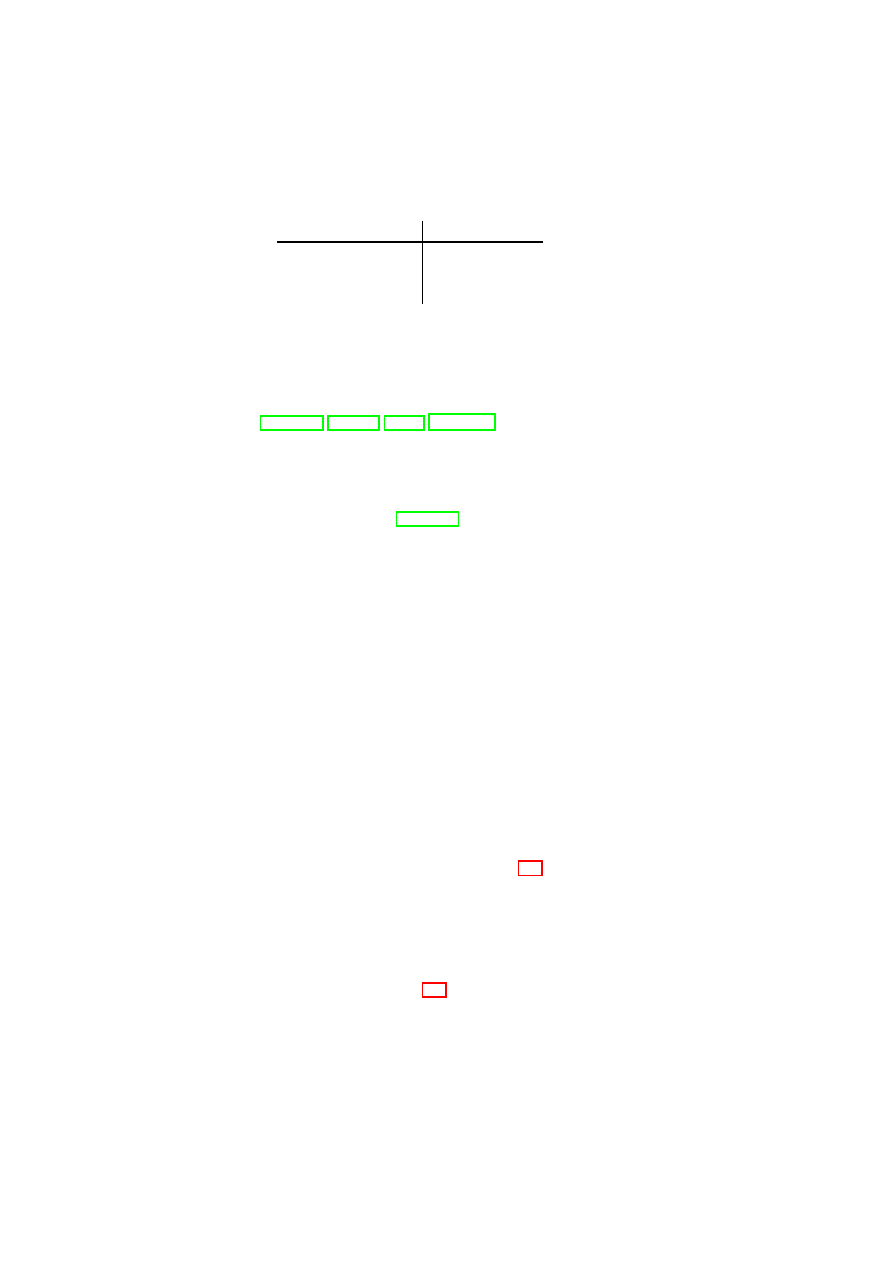
Table 3.1: High-level Directed Flow Control Matrix for Internet
D
I
, DMZ
D
D
,
and Intranet
D
i
(
1
allows information flow, whereas
0
denies it).
From / to
D
I
D
D
D
i
D
I
1
1
0
D
D
0
1
1
D
i
0
1
1
security objectives as well as the prerequisites for becoming a member of a domain.
Isolation and Permitted Flows in Data Centers
Proper customer separation in a virtualized environment requires the logical sep-
aration of all resources that belong to one TVD from those of another TVD. As
mentioned above, this can either be achieved by assigning each resource only to a
single domain or by enforcing flow control to limit the information flow through
shared resources that belong to multiple TVDs.
By default, a VPE and its local memory belong to a single TVD. If VPEs are
assigned to two or more TVDs they act as a gateway allowing controlled infor-
mation flow between TVDs. This includes their system image and swap-files. To
consistently enforce flow control between domains, we need to control the data
flow in shared VPEs, storage, and other devices.
Allowed information flows can be represented by a simple flow control matrix
as depicted in Table 3.1. Note that this matrix is directional, i.e., it might allow
flows in one direction but not in the opposite direction. If flow policies between
two TVDs are asymmetric, only shared resources that can enforce these policies
are permitted. Device-specific policies (network, storage) can then refine these
basic rules. If an information flow is not permitted, then also shared resources are
not permitted between these TVDs.
Membership Requirements
Membership requirements define under what conditions resources may join a do-
main. From a high-level policy perspective, several criteria can be applied to decide
whether an entity is allowed to join a domain, for example:
•
Certificates: An authority defined by the TVD policy can certify a resource
to be member of a TVD.
•
Attestation Credentials: A resource may prove its right to join a TVD us-
ing integrity credentials, e.g., by means of Trusted Computing functionality,
such as remote attestation.
•
White-listing: Only entities that are listed on a white-list can join.
OpenTC Document D05.5/V01 – Final R7343/2008/11/11/OpenTC Public (PU)

CHAPTER 3. POLICY ENFORCEMENT FOR VIRTUAL DATACENTERS
17
In general, a resource may need to show proper credentials to prove that it ful-
fills certain properties [SS05] before allowing the resource to join the TVD. The
validations of these properties are usually done on a per-type basis. This means
that, e.g., the requirements for a shared resource are usually stronger than the re-
quirements for a TVD-internal resource.
One way of formalizing the network membership requirements is to define a
function
M
:
T
→
2
P
, where
(
P,
≤
)
is a lattice of security properties. A machine
m
with a set
p
m
of security properties may be permitted to join the TVD
t
if and
only if
∀
p
∈
M
(
t
) :
∃
p
′
∈
p
m
such that
p
′
≥
p
. In other words,
m
is permitted to
join
t
if and only if there is at least one property of
m
that satisfies each security
requirement of
t
.
3.1.3
Example Policy Refinements for Protected Resources
Policies alone are not sufficient to enforce customer separation. Ultimately, one
needs to transform these policies into data-center configurations and security mech-
anisms specific to each resource (e.g., VLAN configuration). To do so, we intro-
duce a policy management scheme that accepts high-level domain policies and
transforms them into resource-specific low-level policies and configurations.
Refinement Model
The high-level policy defines the basic flow control, protection, and admission
requirements. We aim at enforcing these high-level objectives throughout all re-
sources in the data center.
In the high-level model, flow control is specified by a simple matrix that de-
fines whether flows are permitted. This however is not sufficiently fine-grained for
specific resources. TVDs, for example, want to restrict their flow across bound-
aries by means of firewall rules. As a consequence, we need to introduce a notion
of policy refinement [Wes01], because as translation moves towards lower levels of
abstraction, it will require additional information (e.g., physical arrangement of the
data center, “subjective” trust information) to be correctly and coherently executed.
Our notion of policy refinement mandates the enforcement of “no flow” objec-
tives while allowing each resource to refine what it means so that flows are permit-
ted and how exactly unauthorized flows shall be prevented. Similarly, we do not
allow resources to deviate from the confidentiality/integrity objectives; however,
certain resources can be declared trusted so that they may enforce these objectives
without additional security mechanisms such as encryption or authentication.
Similarly, the fact that admission is restricted is then refined by specific admis-
sion control policies that are enforced by the underlying infrastructure.
Note that conflict detection and resolution [Wes01, LS99] can later be used to
extend this simple notion of refinement. However, we currently stay on the safe
OpenTC Document D05.5/V01 – Final R7343/2008/11/11/OpenTC Public (PU)
18
OpenTC D05.5 – Design and Concept of a Trusted Virtual Datacenter
Table 3.2: Example Network Flow Control Policy Matrix for Three TVDs.
Enforced by/flow to
D
I
D
D
D
i
D
I
1
P
ID
0
D
D
0
1
P
Di
D
i
0
P
Di
1
side: connections are only possible if both TVDs allow them. Similarly, if one
domain requires confidentiality, information flows are only allowed to TVDs that
also require confidentiality. Other schemes for more elaborate flow control have
been proposed in [EASH05, CBL07, N. 01, FWH
+
01].
Network Security Policies
We now survey the policy model of [CDRS07] and show how it related to the
corresponding high-level policy. Similar to our high-level policies, there are two
types of policies governing security in the network. The first limits flow between
networks, whereas the second defines membership requirements to each network.
Network Security Policies across TVDs
A policy covers isolation and flow con-
trol between TVDs as well as integrity and confidentiality against outsiders. These
basic security requirements are then mapped to appropriate policies for each re-
source. For example, from a networking perspective, isolation refers to the re-
quirement that, unless the inter-TVD policies explicitly allow such an information
flow, a dishonest VPE in one TVD cannot (1) send messages to a dishonest VPE in
another TVD (information flow), (2) read messages sent on another TVD (confi-
dentiality), (3) alter messages transmitted on another TVD (data integrity), and (4)
become a member of another TVD network (access control).
TVDs often constitute independent organizational units that may not trust each
other. If this is the case, a communication using another TVD can be established
(see the communication between TVD A and B in Figure 3.1).
The advantage of such a decentralized enforcement approach is that each TVD
is shielded from security failures in other TVDs. For networks, the main inter-
TVD security objectives are information flow control among the TVDs as well as
integrity and confidentiality protection of the channel.
An information flow control matrix is a simple way of formalizing these
system-wide flow control objectives. Table 3.2 shows a sample matrix for the three
example TVDs introduced earlier. Each matrix element represents a policy spec-
ifying both permitted in-bound and out-bound flows between a pair of TVDs, as
enforced by one of the TVDs. The
1
elements along the matrix diagonal convey
the fact that there is free information flow within each TVD. The
0
elements in the
OpenTC Document D05.5/V01 – Final R7343/2008/11/11/OpenTC Public (PU)

CHAPTER 3. POLICY ENFORCEMENT FOR VIRTUAL DATACENTERS
19
matrix are used to specify that there should be no direct information flow between
two TVDs, e.g., between the Internet
D
I
and the intranet
D
i
. Care must be taken
to ensure that the pairwise TVD policies specified in the information flow control
matrix do not accidentally contradict each other or allow undesired indirect flow.
In our practical realization these network flow policies are implemented by firewall
rules.
Intra-TVD Network Security Policy
Within a TVD, all VPEs can freely com-
municate with each other while observing TVD-specific integrity and confidential-
ity requirements. For this purpose, the underlying infrastructure may ensure that
intra-TVD communication only takes place over an authenticated and encrypted
channel (e.g., IPSec), or alternatively, a trusted network
1
.
Towards Storage Security Policies
Virtual disks attached to VPEs must retain the advantages offered by storage vir-
tualization while at the same time enforcing TVD security policies. Advantages
of storage virtualization include improved storage utilization, simplified storage
administration, and the flexibility to accommodate heterogeneous physical storage
devices.
Different groups of virtual disks may exist for different purposes. For example,
the disk images that can be mounted for web-server VMs would be different from
those for database-server VMs. A virtual disk may be attached to multiple VMs
Inter-TVD Storage Security
A virtual disk has a single label corresponding to
the TVD it belongs to. Whenever a virtual machine operates on virtual storage, the
global flow matrix described in Section 3.1 needs to be satisfied. This is guaranteed
by the following policy refinement rules that define the allowed interactions:
1. A machine in domain
TVD
A
can write to a disk of domain
TVD
B
iff flow
from domain
TVD
A
to domain
TVD
B
is permitted.
2. A machine in domain
TVD
A
can read from a disk of domain
TVD
B
iff flow
from domain
TVD
B
to domain
TVD
A
is permitted.
Table 3.3 shows the resulting disk flow control policy. Note that as flow within
a domain is always allowed, this implies that disks of the same domain as the
machine may always be mounted read/write.
By default, we consider the content of a disk to be confidential. That is, if
a given domain does not declare a given storage medium as trusted, we deploy
whole-disk encryption using a key that is maintained by the TVD. Another aspect
reflected in the disk policies is the fact that we have a notion of blank disks. Once
1
A network is called trusted with respect to a TVD security objective if it is trusted to enforce
the given objective transparently. For example, a server-internal Ethernet can often be assumed to
provide confidentiality without any need for encryption.
OpenTC Document D05.5/V01 – Final R7343/2008/11/11/OpenTC Public (PU)

20
OpenTC D05.5 – Design and Concept of a Trusted Virtual Datacenter
Table 3.3: Example of a Refined Disk Policy Matrix for Three TVDs.
Disk/VPE
D
I
D
D
D
i
D
I
r/w
w
0
D
D
r
r/w
r/w
D
i
0
r/w
r/w
Blank
r/
r/
r/
w
→
D
I
w
→
D
D
w
→
D
i
they are written by another domain, they change color, and are then associated with
this other domain.
Intra-TVD Storage Security
For protecting the data in a particular TVD, virtual
storage may in addition specify whether the disk is encrypted, which conditions on
the system must be satisfied before a disk may be re-mounted by a VPE that has
previously unmounted the disk, and whether shared mounting by multiple systems
is allowed. To be compatible with a high-level policy, a disk either has to be trusted
or else confidentiality requires encryption while integrity requires hash-trees pro-
tecting the disk. Similarly, membership restrictions require bookkeeping of disks
and management of access of VPEs to disks.
3.2
Unified Policy Enforcement for Virtual Data Centers
In this section, we introduce a TVD-based policy enforcement framework that
orchestrates the deployment and enforcement of the type of policies we presented
in Section 3.1 across the data center. Existing storage and network virtualization
technologies as well as existing Trusted Computing components (in software and
hardware) are the building blocks of our solution. Our framework (1) combines
these technologies to realize TVDs and (2) orchestrates them using the TVD in-
frastructure, which provisions the appropriate security mechanisms.
3.2.1
TVD Infrastructure
The TVD infrastructure consists of a management layer and an enforcement
layer. The TVD management layer includes TVD masters, proxies, and factories,
whereas the TVD enforcement layer consists of various security services. Each
TVD is identified by a unique TVD master that orchestrates TVD deployment and
configuration. The TVD master can be implemented as a centralized entity or have
a distributed fault-tolerant implementation. The TVD master contains a repository
of high-level TVD policies and credentials (e.g., VPN keys). The master also ex-
poses a TVD management API through which the TVD owner can specify those
policies and credentials. In the deployment phase, the TVD master first verifies the
OpenTC Document D05.5/V01 – Final R7343/2008/11/11/OpenTC Public (PU)
CHAPTER 3. POLICY ENFORCEMENT FOR VIRTUAL DATACENTERS
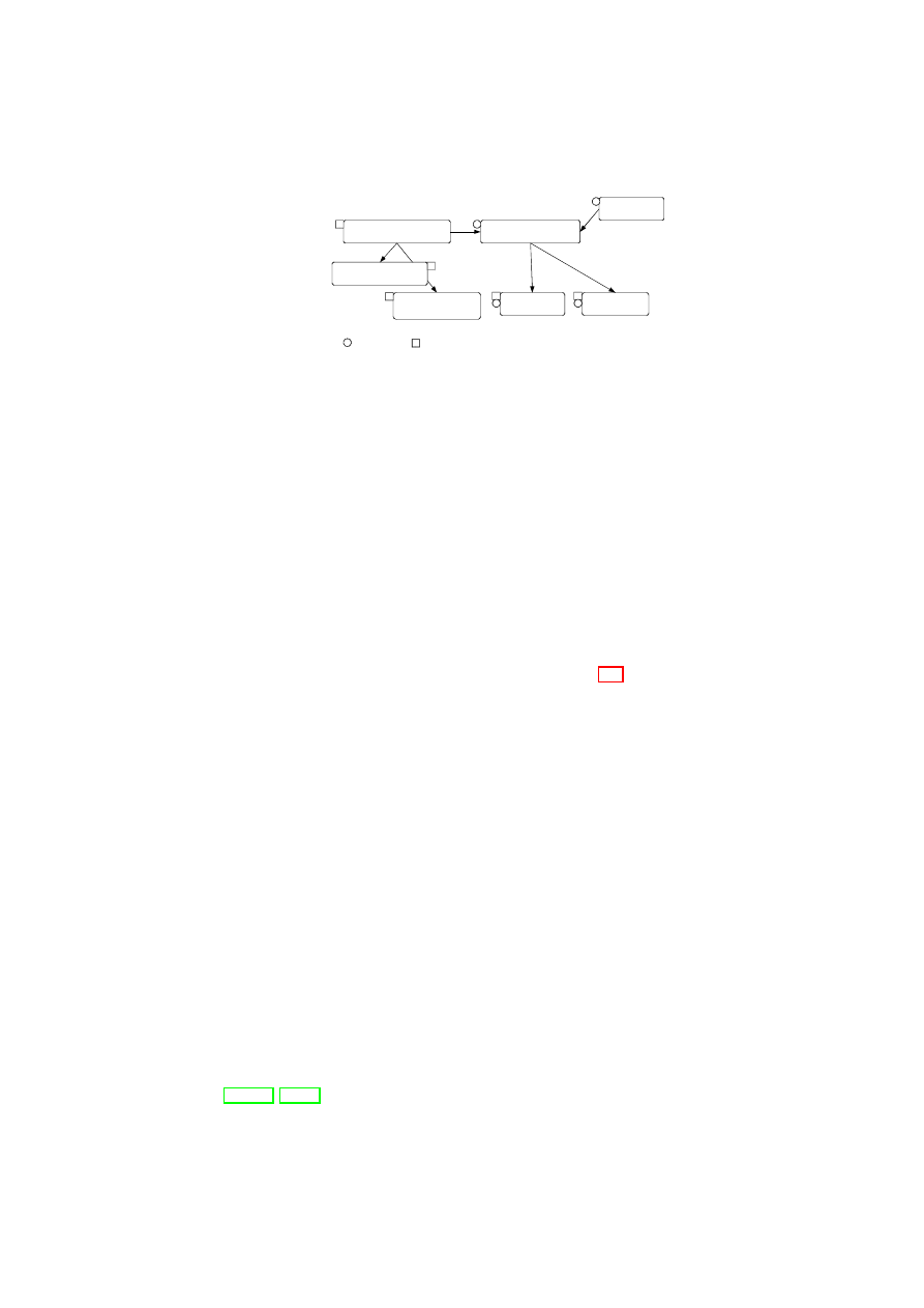
21
Compartment Manager
TVD Proxy
TVD Master
Network Manager
(sub-proxy)
Storage Manager
(sub-proxy)
Virtual Device Manager
Integrity Manager
TVD component
Security service
Figure 3.2: TVD Components and Security Services.
suitability and capability of the physical host (which we refer to as pre-admission
control). It then uses a generic TVD factory service to spawn a TVD proxy, which
acts as the local delegate of the TVD master dedicated to that particular host. The
TVD proxy is responsible for (1) translation of high-level TVD policies into low-
level platform-specific configurations, (2) configuration of the host and security
services with respect to the translated policies, and (3) interaction with the security
services in TVD admission and flow control.
Security services implement the security enforcement layer of our TVD in-
frastructure. They run in a trusted execution environment on each physical host
(e.g., Domain-0 in Xen) and (1) manage the security configuration of the hyper-
visor, (2) provide secure virtualization of resources (e.g., virtual devices) to the
VMs, and (3) provide support to TVD proxies in enforcing flow and access con-
trol policies within and across TVD boundaries. Figure 3.2 shows a high-level list
of security services and their interaction with the TVD components. Most impor-
tantly, the compartment manager service manages the life-cycle of VMs in both
para-virtualized and fully virtualized modes. This service works in collaboration
with the TVD proxy to admit VMs into TVDs. The integrity manager service
implements Trusted Computing extensions and assists the TVD proxy in host pre-
admission and VM admission control. The virtual network manager and virtual
storage manager services are invoked by the TVD proxy. They implement re-
source virtualization technologies and enforce parts of the high-level TVD policies
that are relevant to their operation. Lastly, the virtual device manager service han-
dles the secure resource allocation and setup of virtual devices assigned to each
VM.
Our TVD infrastructure is geared towards automated deployment and enforce-
ment of security policies specified by the TVD master. Automated refinement and
translation of high-level policies into low-level configurations are of particular in-
terest. For example, for information flow between two hosts in a trusted data-center
environment, other mechanisms need to be in place than for a flow between two
hosts at opposite ends of an untrusted WAN link. In the latter case, the hosts should
be configured to allow communication between them only through a VPN tunnel.
Another important consideration is policy conflict detection and resolution
[Wes01, LS99]. In fact, conflicting high-level policies (e.g., a connection being
OpenTC Document D05.5/V01 – Final R7343/2008/11/11/OpenTC Public (PU)
22
OpenTC D05.5 – Design and Concept of a Trusted Virtual Datacenter
allowed in the inter-TVD policy but disallowed in the intra-TVD policy) can po-
tentially result in an incorrect configuration of the underlying infrastructure. We
cannot solely rely on the TVD owner to specify conflict-free policies. It is im-
portant to detect policy conflicts and provide feedback to the owner in case one is
detected. In the present prototype, policy refinement is performed manually. The
result is a set of configuration files that we use for configuring the security services
at the policy enforcement layer (e.g., the virtual networking infrastructure). In fu-
ture work, we will investigate the automation of this step using, for example, the
IETF policy model [RYG00] and various graph-based mechanisms from the litera-
ture. We will also investigate different techniques for resolving conflicting policies
[EASH05, CBL07, N. 01, FWH
+
01].
3.2.2
Virtual Networking Infrastructure
Virtual networking (VNET) technologies enable the seamless interconnection of
VMs that reside on different physical hosts as if they were running on the same
machine. In our TVD framework, we employ multiple technologies, including
virtual switches, Ethernet encapsulation, VLAN tagging, and VPNs, to virtualize
the underlying network and securely group VMs that belong to the same TVD. A
single private virtual network is dedicated to each TVD, and network separation
is ensured by connecting the VMs at the Ethernet level. Logically speaking, we
provide a separate “virtual infrastructure” for each TVD in which we control and
limit the sharing of network resources (such as routers, switches) between TVDs.
This also provides the TVD owner with the freedom to deploy a wide range of
networking solutions on top of the TVD network infrastructure. Network address
allocations, transport protocols, and other services are then fully customizable by
the TVD owner and work transparently as if the VMs were in an isolated physical
network. To maintain secrecy and confidentiality of network data (where neces-
sary), network communication is established over encrypted VPN tunnels. This
enables the transparent use of untrusted networks between physical hosts that con-
tain VMs within the same TVD to provide a seamless view of the TVD network.
In this section, we introduce the technologies we use to implement a security-
enhanced VNET infrastructure for TVD owners. The concept of virtual switching
is central to our architecture, which is then protected by existing VPN technologies
that provide data confidentiality and integrity where needed. The VNET infras-
tructure acts as the local enforcer of VNET policies. As described in Section 3.1.3,
these policies are based on the high-level TVD policies and translated into net-
work configurations by the TVD proxy. The proxy then deploys the whole VNET
infrastructure with respect to the translated configuration.
Virtual Switching
The virtual switch (vSwitch) is the central component of the virtual networking
infrastructure and operates similarly to a physical switch. It is responsible for
OpenTC Document D05.5/V01 – Final R7343/2008/11/11/OpenTC Public (PU)
CHAPTER 3. POLICY ENFORCEMENT FOR VIRTUAL DATACENTERS
23
VM
VM
Eth
erIP
Host C
Host D
Host A
VPN
WAN
vSwitch
VM
VM
VM
VM
VM
VM VM
VM
vSwitch
vSwitch
VM
VM
Tag
ge
r
vSwitch
Eth
erIP
VLAN Switch
Host B
VM
VM
Tag
ge
r
vSwitch
VPN
VPN
Tag
ge
r
Eth
erIP
Eth
erIP
VPN
Eth
erIP
VPN
Figure 3.3: General vSwitch Architecture.
network virtualization and isolation, and enables a virtual network to span multi-
ple physical hosts. To do so, the vSwitch uses EtherIP [IET02] and VLAN tag-
ging [IEE98] to insert VLAN membership information into every network packet.
The vSwitch also implements the necessary address-mapping techniques to direct
packets only to those machines that host member VMs. Virtual switches provide
the primitives for implementing higher-level security policies for networking and
are configured by the higher-level TVD management layer.
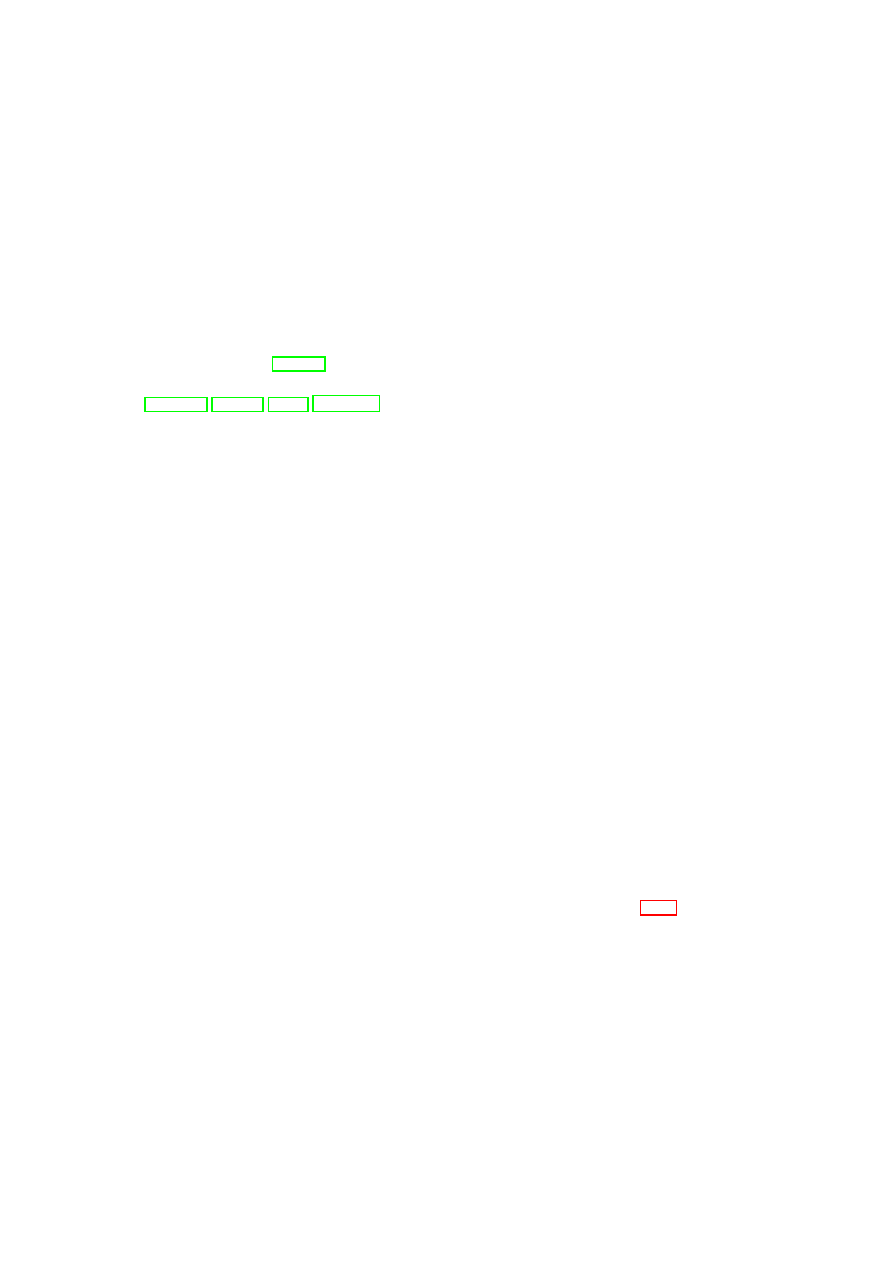
Figure 3.3 illustrates an example architecture in which physical machines host
multiple VMs with different TVD memberships (the light and dark shades indicate
different TVDs). Hosts A, B, and D are virtualized machines, whereas Host C is
non-virtualized. Furthermore, Hosts A, B, and C reside on the same LAN, and thus
can communicate directly using the trusted physical infrastructure without further
protection (e.g., traffic encryption). For example, the light VMs hosted on Hosts
A and B are inter-connected using the local VLAN-enabled physical switch. In
this case, the physical switch separates the TVD traffic from other traffic passing
through the switch using VLAN tags. Similarly, the dark VMs hosted on Host
A and the non-virtualized Host C are seamlessly inter-connected using the local
switch. In contrast, connections that require IP connectivity are routed over the
WAN link. The WAN cloud in Figure 3.3 represents the physical network in-
frastructure able to deal with TVD-enabled virtual networks; it can include LANs
with devices capable of VLAN tagging and gateways to connect the LANs to each
other over (possibly insecure) WAN links. For connections that traverse untrusted
medium, we employ EtherIP encapsulation to denote TVD membership and addi-
tional security measures (such as encryption) to ensure compliance with the confi-
dentiality and integrity requirements.
OpenTC Document D05.5/V01 – Final R7343/2008/11/11/OpenTC Public (PU)

24
OpenTC D05.5 – Design and Concept of a Trusted Virtual Datacenter
Consolidation
Access Control & Encryption
TVD A
TVD B
TVD C
Heterogeneous
Physical Storage
Per-TVD
Raw Storage
Per-TVD
Virtual Storage
TVD A
TVD B
TVD C
Metadata
Figure 3.4: Security Enforcement for Virtualized Storage.
Virtual Private Networking
In Figure 3.3, VMs hosted on Host D are connected to the other machines over a
WAN link. A practical setting in which such a connection might exist would be
an outsourced remote resource connected to the local data center through the In-
ternet. As an example, lightly shaded VMs on Host D connect to the lone VM on
Host B over this untrusted link. In this setting, we use a combination of EtherIP
encapsulation and VPN technology to ensure the confidentiality and integrity of
the communication. To do so, we use point-to-point VPN tunnels with OpenVPN
that are configured via the TVD proxy from the TVD policies. This enables re-
configuration of the topology and the involved VPNs within a TVD from a single
administration point, the TVD Master.
TVD policies distributed from the TVD master to the TVD proxy also include
the secret key for the VPN along with other VPN-specific settings. On a physical
host, the VPN’s endpoint is represented as a local virtual network interface (vif)
that is plugged into the appropriate vSwitch controlled by the TVD proxy. The
vSwitch then decides whether to tunnel the communication between VMs, and if
so, uses the VPN module to establish the tunnel and access the VPN secret for
traffic encryption and decryption.
3.2.3
Virtual Storage Infrastructure
We focus on a simplified security management of virtualized storage. Broadly
speaking, storage virtualization abstracts away the physical storage resource(s). It
is desirable to allow a storage resource to be shared by multiple host computers,
and also to provide a single storage device abstraction to a computer irrespective
of the underlying physical storage, which may be a single hard disk, a set of hard
disks, a Storage Area Network (SAN), etc. To satisfy both requirements, stor-
age virtualization is typically done at two levels. The first level of virtualization
involves aggregating all the (potentially heterogeneous) physical storage devices
into one or more virtual storage pools. The aggregation allows more centralized
and convenient data management. The second level of virtualization concerns the
unified granularity (i.e., blocks or files) at which data in each pool is presented to
the higher-level entities (operating systems, applications, or VMs).
OpenTC Document D05.5/V01 – Final R7343/2008/11/11/OpenTC Public (PU)

CHAPTER 3. POLICY ENFORCEMENT FOR VIRTUAL DATACENTERS
25
Figure 3.4 shows our storage security enforcement architecture, in which exist-
ing heterogeneous physical storage devices are consolidated into a joint pool. This
virtual storage pool is then subdivided into raw storage for each TVD. Each raw
storage volume has an owner TVD (indicated by the labels TVD A, TVD B, and
TVD C at the per-TVD raw storage layer in the figure). In addition, when a volume
may have to be shared among multiple TVDS, there is also a set of member TVDs
associated with it. The access control and encryption layer helps enforce the owner
TVD’s storage-sharing policies, e.g., enforcing read, write, create, and update ac-
cess permissions for the member TVDs. This layer is a logical layer that in reality
consists of the virtual storage managers (part of the security services) located on
each physical platform containing the owner TVD’s VPEs. The owner TVD’s vir-
tual storage manager on each physical platform is responsible for enforcing the
owner TVD’s storage security policies (see Section 3.1.3) on these volumes. If a
certain intra-TVD security policy requires confidentiality and does not declare the
medium as trusted, the disk is encrypted using a key belonging to the owner TVD.
2
If conditions for (re-)mounting a disk have been defined, the disk is also encrypted
and the key is sealed against the TCB while including these conditions into the un-
sealing instructions. The policy and meta-data are held on a separate raw volume
that is only accessible by the data-center infrastructure.
An administrator of a domain may request that a disk be mounted to a partic-
ular VM in a particular mode (read/write). In Xen, the disk is usually mounted in
the management machine Domain-0 as a back-end device and then accessed by a
guest domain via a front-end device. The virtual storage manager on the platform
validates the mount request against the policies of both the TVD the VM is part
of and the owner TVD for the disk. Once mounted, appropriate read-write per-
missions are granted based on the flow control policy for the two TVDs, e.g., read
access is granted only if the policies specified in the disk policy matrix allow the
VM’s TVD such an access to the disk belonging to the owner TVD.
3.2.4
TVD Admission Control
When a VM is about to join a TVD, different properties will be verified by the
local TVD proxy to ensure that policies of all the TVDs that the VM is currently
a member of as well as of the TVD that it wants to join are not violated. If the
verification is successful, then the VM will be connected to that TVD. The TVD
admission control protocol is the procedure by which the VM gets connected to the
TVD. In the case of a VM joining multiple TVDs, the admission control protocol
is executed for each of those TVDs. We now describe the steps of the protocol.
We assume that the computing platform that executes the VM provides mech-
anisms that allow remote parties to convince themselves about its trustworthiness.
Example mechanisms include trusted (authenticated) boot and the remote attesta-
tion protocol based on TPM technology.
2
For efficiency reasons, we currently do not provide integrity protection.
OpenTC Document D05.5/V01 – Final R7343/2008/11/11/OpenTC Public (PU)

26
OpenTC D05.5 – Design and Concept of a Trusted Virtual Datacenter
TVD Proxy Initialization Phase:
To allow a VM to join a TVD, the platform
hosting the VM needs access to the TVD policy, and upon successful admission,
to TVD secrets, such as the VPN key. For this purpose, TVD proxy services are
started on the platform for each TVD whose VPEs may be hosted . The TVD proxy
can be started at boot time of the underlying hypervisor, by a system service, or by
the VM itself, as long as the TVD proxy is strongly isolated from the VM.
Pre-Admission Phase:
When a VPE belonging to the TVD is going to be hosted
on the platform for the first time, the TVD master has to establish a trust relation
with the platform running the VM, specifically with the TVD proxy. We call this
step the pre-admission phase, and it involves the establishment of a trusted channel
between the TVD master and the TVD proxy. The trusted channel allows the TVD
master to verify the integrity of the TVD proxy and the underlying platform. After
the trusted channel is established and the correct configuration of proxy verified,
the TVD master can send the TVD policies and credentials (such as VPN key) to
the TVD proxy.
Admission Control Phase:
The Compartment Manager (part of the platform se-
curity services shown in Figure 3.2) is responsible for starting new VMs. The
Compartment Manager loads the VM configuration and enforces the security di-
rectives with the help of the Integrity Manager (also part of the platform security
services shown in Figure 3.2). The security directives may include gathering the
VM state information, such as the VM configuration, kernel, and disk(s) that are
going to be attached to the VM.
If the VM configuration states that the VM should join one or more TVDs,
then the Compartment Manager interacts with the corresponding TVD proxy and
invokes TPM functions to attest the state of the VM. The TVD proxy verifies cer-
tain properties before allowing the VM to join the TVD. More concretely, the TVD
proxy has to ensure that
•
the VM fulfills the integrity requirements of the TVD;
•
the information flow policies of all TVDs the VM will be a member of will
not be violated;
•
the VM enforces specific information flow rules between TVDs if such rules
are required by the TVD policy, and that
•
the underlying platform (e.g., the hypervisor and attached devices) fulfills
the security requirements of the TVD.
Platform verification involves matching the security requirements with the plat-
form’s capabilities and mechanisms instantiated on top of these capabilities. For
example, suppose that data confidentiality is a TVD requirement. Then, if hard
disks or network connections are not trusted, additional mechanisms, such as block
encryption or VPN (respectively), need to be instantiated to satisfy the requirement.
OpenTC Document D05.5/V01 – Final R7343/2008/11/11/OpenTC Public (PU)

CHAPTER 3. POLICY ENFORCEMENT FOR VIRTUAL DATACENTERS
27
TVD Join Phase:
If the VM and the provided infrastructure fulfill all TVD re-
quirements, a new network stack is created and configured as described in Sec-
tion 3.2.2. Once the Compartment Manager has started the VM, it sends an attach
request to the corresponding TVD vSwitch. Once the VM is connected to the
vSwitch, it is a member of the TVD.
OpenTC Document D05.5/V01 – Final R7343/2008/11/11/OpenTC Public (PU)

Part II
Building Blocks and Future
Directions
28

Chapter 4
Automated Provisioning of
Secure Virtual Networks
S. Cabuk, C. Dalton (HPL), H. Ramasamy, M. Schunter (IBM)
4.1
Introduction to Secure Virtual Networking
Virtualization allows the abstraction of the real hardware configuration of a com-
puter system. A particular challenge of virtualization is isolation between poten-
tially distrusting virtual machines and their resources. The machine virtualization
alone provides reasonable isolation of computing resources such as memory and
CPU between guest domains. However, the network remains to be a shared re-
source as all traffic from guests eventually pass through a shared network resource
(e.g., a physical switch) and end up on the shared physical medium. Today’s VMM
virtual networking implementations provide simple mechanisms to bridge all VM
traffic through the actual physical network card of the physical machine. This level
of isolation can be sufficient for individual and small enterprise purposes. How-
ever, a large-scale infrastructure (e.g., a virtualized data center) that hosts services
belonging to multiple customers require further guarantees on customer separation,
e.g., to avoid accidental or malicious data leakage.
Outline
Our focus is on security-enhanced network virtualization, which (1) al-
lows groups of related VMs running on separate physical machines to be connected
together as though they were on their own separate network fabric, and (2) enforces
cross-group security requirements such as isolation, authentication, confidentiality,
integrity, and information flow control. The goal is to group related VMs (e.g.,
VMs belonging to the same customer in a data center) distributed across several
physical machines into virtual enclave networks, so that each group of VMs has
the same protection as if the VMs were hosted on a separate physical LAN. Our
solution for achieving this goal also takes advantage (whenever possible) of the
29

30
OpenTC D05.5 – Design and Concept of a Trusted Virtual Datacenter
fact that some VMs in a group may be co-hosted on the same hardware; it is not
necessary to involve the physical network during information flow between two
such VMs.
The concept of Trusted Virtual Domains or TVDs was put forth by Bussani
et al. [BGJ
+
05] to provide quantifiable security and operational management for
business and IT services, and to simplify overall containment and trust manage-
ment in large distributed systems. Informally speaking, TVDs can be thought of
as security-enhanced variants of virtualized network zones, in which specified se-
curity policies can be automatically enforced. We describe the first practical real-
ization of TVDs using a secure network virtualization framework that guarantees
reliable isolation and flow control requirements between TVD boundaries. The re-
quirements are specified by TVD policies, which are enforced dynamically despite
changing TVD membership, policies, and properties of the member VMs. The
framework is based on existing and well-established network virtualization tech-
nologies such as Ethernet encapsulation, VLAN tagging, virtual private networks
(VPNs), and network access control (NAC) for configuration validation.
Our main contributions are (1) combining standard network virtualization tech-
nologies to realize TVDs, and (2) orchestrating them through a management frame-
work that is oriented towards automation. In particular, our solution aims at auto-
matically instantiating and deploying the appropriate security mechanisms and net-
work virtualization technologies based on an input security model, which specifies
the required level of isolation and permitted network flows.
The remainder of the chapter is organized as follows. In Section 4.2, we pro-
vide an overview of our security objectives and describe the high-level framework
to achieve the objectives. We introduce the networking components required for
our framework in Section 4.3 and describe how they can be orchestrated to enforce
TVD policies. In Section 4.4, we present the TVD security model and the compo-
nents constituting the TVD infrastructure. In Section 4.5, we cover the dynamic
aspects of TVD deployment including TVD establishment, population, and admis-
sion control. In Section 4.6, we describe a Xen-based prototype implementation
of our secure virtual networking framework and report our performance results in
Section 4.7. Finally, we conclude and discuss future extensions in Section 4.8.
4.2
Design Overview
At a high level, our secure network virtualization framework consists of a network-
ing infrastructure and a TVD infrastructure. The networking infrastructure enables
the mapping from physical to logical network topologies that we use to separate
customer networks. The TVD infrastructure configures the network devices and
instantiates the appropriate set of mechanisms to realize the TVD security objec-
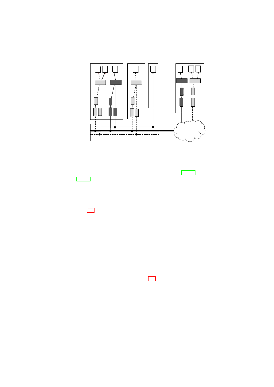
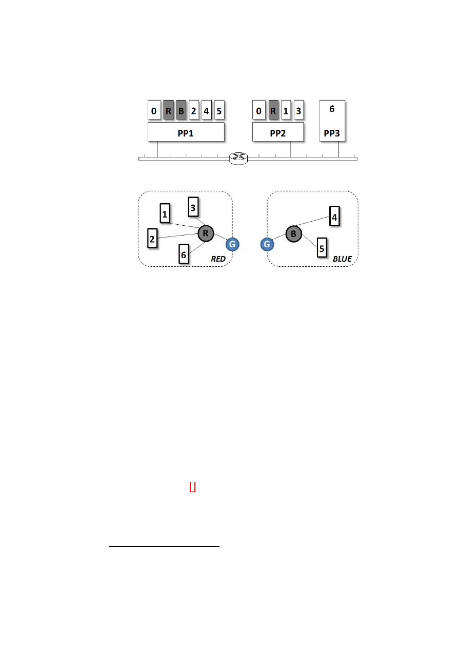
tives. Figure 4.1 illustrates an example mapping. Figure 4.1(a) shows the actual
layout of the physical infrastructure that includes virtualized and non-virtualized
platforms and networking devices. Figure 4.1(b) shows the logical layout as seen
OpenTC Document D05.5/V01 – Final R7343/2008/11/11/OpenTC Public (PU)
CHAPTER 4. AUTOMATED PROVISIONING OF SECURE VIRTUAL NETWORKS
31
(a) Physical view.
(b) Logical view.
Figure 4.1: An example TVD-based virtual network mapping.
R
and
B
provide
switching for red and blue TVDs, respectively.
G
is a virtual gateway that controls
inter-TVD communication (not shown in (a) for clarity).
by each TVD owner (i.e., red and blue). In this section, we provide an overview
of the mechanisms that enable this mapping while enforcing TVD policies within
and across domains.
4.2.1
High-level Objectives
We are specifically interested in virtualized data centers that host multiple cus-
tomers with potentially conflicting interests. In this setting, the TVD-based net-
working framework has the following functional and security objectives:
Virtual Networking The framework should support arbitrary logical network
topologies that involve virtualized and non-virtualized platforms alike.
Customer Separation The framework should provide sufficient isolation guaran-
tees to customers, i.e., information leakage should be minimized between
customer domains
1
.
Unified Policy Enforcement The framework should enforce domain policies
within and across domains in a seamless manner. The policies define in-
tegrity, confidentiality, and isolation requirements for each domain, and in-
formation flow control requirements between any two domains.
1
In this chapter, we do not address indirect communication channels (e.g., covert channels).
OpenTC Document D05.5/V01 – Final R7343/2008/11/11/OpenTC Public (PU)

32
OpenTC D05.5 – Design and Concept of a Trusted Virtual Datacenter
Autonomous Management The framework should deploy and maintain customer
TVDs in an automated manner, and provide customers the tools to manage
their TVDs with no direct or side effect on other customer TVDs.
4.2.2
Overview of Networking Infrastructure
Virtual network extensions enable groups of related VMs running on separate phys-
ical machines to be connected together as though they were on their own separate
network fabric. This allows the creation of arbitrary virtual LAN (VLAN) topolo-
gies independent of the particular underlying physical network topology. It also
provides a level of isolation between VLAN segments.
A virtual network is comprised of virtual and physical network entities. The
central VLAN component is a virtual switch. There is a single virtual switch per
VLAN segment. A VM appears on a particular VLAN segment if one of its virtual
network interface cards (Venice) is “plugged” into one of the switch ports on the
virtual switch forming that segment. The virtual switch behaves like a normal
physical switch and coordinates traffic to and from member VMs. Figure 4.1(b)
shows two virtual switches
R
and
B
that coordinate the traffic for red and blue
segments. In the foregoing arrangement, each virtual switch resides in a small VM
of its own as shown in Figure 4.1(a). Additional VPN and NAC modules can be
employed to strengthen security properties on untrusted communication lines and
to authenticate VMs prior to VLAN admission, respectively.
4.2.3
Overview of TVD Infrastructure
A TVD is represented by a set of distributed virtual processing elements (VPE)
(e.g., virtual machines and virtual switches) and a communication medium in-
terconnecting the VPEs. The TVD provides a policy and containment boundary
around those VPEs. At a high level, the TVD policy has three aspects: (1) mem-
bership requirements for the TVD, (2) interaction among VPEs of that TVD, and
(3) interaction of the TVD with other TVDs and the outside world. VPEs within
each TVD can usually communicate freely and securely with each other. At the
same time, they are sufficiently isolated from outside VPEs, including those be-
longing to other TVDs. From a networking perspective, isolation loosely refers to
the requirement that a dishonest VPE in one TVD cannot send messages to a dis-
honest VPE in another TVD, unless the inter-TVD policies explicitly allow such
an information flow.
Each TVD has an associated infrastructure whose purpose is to provide a uni-
fied level of security to member VPEs, while restricting the interaction with VPEs
outside the TVD to pre-specified, well-defined means only. Unified security within
a domain is obtained by defining and enforcing membership and communication
requirements that the VPEs and networks have to satisfy before being admitted to
the TVD and for retaining the membership. Unified security across domains is
obtained by defining and enforcing flow requirements that the VPEs have to sat-
OpenTC Document D05.5/V01 – Final R7343/2008/11/11/OpenTC Public (PU)

CHAPTER 4. AUTOMATED PROVISIONING OF SECURE VIRTUAL NETWORKS
33
isfy to be able to interact with VPEs in other TVDs. To do so, each TVD defines
rules regarding in-bound and out-bound network traffic. Their purpose is to restrict
communication with the outside world.
The central element in the TVD infrastructure is the TVD master which keeps
track of high-level TVD policies and secrets. TVD masters maintain control over
member VPEs using TVD proxies. There is a single TVD master per TVD and a
single TVD proxy per physical platform. A VPE appears on a particular TVD if
it complies with the membership requirements enforced by the TVD proxy con-
trolling that domain on that physical platform. VPEs communicate freely within
a TVD. Communication across TVDs is controlled by entities configured by TVD
proxies.
4.2.4
Overview of TVD-based Virtual Networking
Virtual networking and TVD infrastructures play complementary roles in meet-
ing the objectives listed earlier. In essence, the VNET infrastructure provides the
tools and mechanisms to enable secure virtual networking in a data center. The
TVD infrastructure defines unified domain policies, and automatically configures
and manages these mechanisms inline with the policy. It also provides customers
the necessary tools to manage their TVDs. Any action by the customer is then
seamlessly reflected on the underlying networking infrastructure. This two-layer
architecture has many advantages:
1. The policy (TVD) and enforcement (VNET) layers are clearly separated
from each other, which yields a modular framework. As a result, other tech-
nologies (e.g., VNET) can be easily deployed in place of the current offering.
2. The policy layer is not restricted to network-type policies. Thus, same poli-
cies can be used to configure and manage, for example, mechanisms to en-
force storage isolation.
3. The policy layer provides a high-level abstraction to customers so that they
can manage their TVDs without worrying about the specifics of the underly-
ing enforcement mechanisms.
4. Automated deployment, configuration, and management of customer TVDs
are desirable capabilities in a virtualized data center that can effectively re-
duce operational costs and leverage virtualization to the fullest extent.
4.3
Networking Infrastructure
In this section, we present the network virtualization layer that enables the creation
of arbitrary virtual topologies on top of the underlying physical network. This
layer also provides the basic mechanisms to help enforce TVD admission and flow
policies at a higher level.
OpenTC Document D05.5/V01 – Final R7343/2008/11/11/OpenTC Public (PU)

34
OpenTC D05.5 – Design and Concept of a Trusted Virtual Datacenter
4.3.1
Aims and Security Requirements
The main aim of our network virtualization extensions is to allow groups of related
VMs running on separate physical machines to be connected together as though
they were on their own separate network fabric. In particular, we would like to cre-
ate arbitrary virtual network topologies independently of the underlying physical
network topology. For example, a group of related VMs may have to be connected
directly together on the same VLAN segment even though, in reality, they may be
at opposite ends of a WAN link separated by many physical LAN segments. Fur-
ther, multiple segmented virtual networks may have to be established on a single
physical network segment to achieve improved security properties such as network
isolation. Our network virtualization extensions are required to inter-operate with
existing non-virtualized entities (e.g., standard client machines on the Internet) and
allow our virtual networks to connect to real networks.
Virtual networking extensions must also adhere to security requirements such
as isolation and confidentiality. In particular, our extensions must isolate the vir-
tual resources used by different VLAN segments as well as the traffic generated
by each. Network connections can be established between VMs that belong to
the same VLAN segment and VMs that belong to different VLAN segments (i.e.,
TVDs). These connections must be secured to meet the security requirements
whenever they are established over untrusted physical infrastructures. Addition-
ally, all entities (virtual or physical) that seek membership to a network segment
must be properly authenticated prior to being admitted to the network.
4.3.2
Network Virtualization
One option for virtual networking is to virtualize at the IP level. However, to
avoid problems regarding the support for non-IP protocols and IP support services
(such as ARP) that sit directly on top of the Ethernet protocol, we have chosen to
virtualize at the Ethernet level.
Our network virtualization extensions allow multiple VMs belonging to dif-
ferent VLAN segments to be securely hosted on one or more physical machine.
The framework provides isolation among various segments using a combination of
VLANs and virtual private networks (VPNs). Each VLAN segment is an Ethernet
broadcast domain and there is one internal VLAN for each security domain (i.e.,
TVD)
2
. An external VLAN may be used for communication with other TVDs and
TVD-external entities. In the absence of a trusted physical network, each VLAN
segment can employ an optional VPN layer to provide authentication, integrity,
and confidentiality.
The virtual networking framework is comprised of a mixture of physical and
virtual networking components. Physical components include physical hosts and
standard physical networking devices such as VLAN-enabled switches and routers.
Virtual entities include VMs, vNICs, virtual switches, virtual routers, and virtual
2
In this chapter, we use both VLAN segment and TVD to denote a security domain.
OpenTC Document D05.5/V01 – Final R7343/2008/11/11/OpenTC Public (PU)

CHAPTER 4. AUTOMATED PROVISIONING OF SECURE VIRTUAL NETWORKS
35
gateways. Each VM has a number of vNICs where each can be associated with
at most one VLAN segment. Each VLAN segment is represented by a virtual
switch or a vSwitch. A VM appears on a particular VLAN if one of its vNICs
is “plugged” into one of the switch ports on the vSwitch forming that segment.
The vSwitch behaves like a normal physical switch. Ethernet broadcast traffic
generated by a VM connected to the vSwitch is passed to all VMs connected to
that vSwitch. Like a real switch, the vSwitch also builds up a forwarding table
based on observed traffic so that non-broadcast Ethernet traffic can be delivered in
a point-to-point fashion to improve bandwidth efficiency.
The vSwitch is designed to operate in a distributed fashion. The VMM on each
physical machine hosting a VM connected to a particular VLAN segment hosts part
of the vSwitch forming that VLAN segment. A component of the VMM captures
the Ethernet frames coming out of a VM’s vNIC. This component is configured
to know which vSwitch the VM is supposed to be connected to. We describe the
vSwitch implementation in detail in Section 4.6.
To enable network virtualization, VM Ethernet frames can be encapsulated
in IP packets or tagged with VLAN identifiers using EtherIP [IET02] and IEEE
802.1Q standards [IEE98], respectively. Virtual switches employ both schemes to
encapsulate or tag each outgoing packet to insert the corresponding VLAN identi-
fier. The choice of which scheme depends on the destination host plus the configu-
ration dictated by the higher-level TVD management layer. The actual encapsula-
tion or tagging of the packet is done by an EtherIP or a VLAN tagging module on
request by the vSwitch.
4.3.3
Virtual Switch and EtherIP
EtherIP is a standard protocol for tunneling Ethernet and 802.3 packets via IP data-
grams and can be employed to expand a LAN over a Wide or Metropolitan Area
Network [IET02]. We employ EtherIP encapsulation as the standard mechanism
to insert VLAN membership information into Ethernet/802.3 frames. To do so,
each tunnel endpoint uses a special network device provided by the operating sys-
tem that encapsulates outgoing Ethernet/802.3 packets in new IP packets. We insert
VLAN membership information (i.e., the VLAN identifier) into the EtherIP header
of each encapsulated packet. The encapsulated packets are then transmitted to the
other side of the tunnel where the embedded Ethernet/802.3 packets are extracted
and transmitted to the destination host that belongs to the same VLAN segment.
Address Mapping
The virtual switch component on a VMM maps the Ethernet address of the encap-
sulated Ethernet frame to an appropriate IP address. This way, the encapsulated
Ethernet frame can be transmitted over the underlying physical network to physi-
cal machines hosting other VMs connected to the same LAN segment that would
have seen that Ethernet traffic had the VMs actually been on a real LAN together.
OpenTC Document D05.5/V01 – Final R7343/2008/11/11/OpenTC Public (PU)

36
OpenTC D05.5 – Design and Concept of a Trusted Virtual Datacenter
The IP address chosen to route the encapsulated Ethernet frames over the underly-
ing physical network depends upon whether the encapsulated Ethernet frame is an
Ethernet broadcast frame or not and also whether the virtual switch has built up a
table of the locations of the physical machines hosting other VMs on a particular
LAN segment based on observing traffic on that LAN.
IP packets encapsulating broadcast Ethernet frames are given a multicast IP
address and sent out over the physical network. Each virtual LAN segment has
an IP multicast address associated with it. All the physical machines hosting VMs
on a particular virtual LAN segment are members of the multicast group for that
virtual LAN segment. This mechanism ensures that all VMs on a particular vir-
tual LAN segment receive all broadcast Ethernet frames from other VMs on that
segment. Encapsulated Ethernet frames that contain a directed Ethernet address
destination are either flooded to all the VMs on a particular LAN segment (using
the IP multicast address as in the broadcast case) or sent to a specific physical ma-
chine IP address. This depends upon whether the virtual switch component on the
encapsulating VM has learned the location of the physical machine hosting the VM
with the given Ethernet destination address based on traffic observation through the
virtual switch.
Requirements Revisited
EtherIP can be used over arbitrary Layer 3 networks. The decision to encapsulate
Ethernet frames from VMs within IP packets allow us to connect different VMs to
the same virtual LAN segment as long as the physical machines hosting those VMs
have some form of IP based connectivity between them, even a WAN link. There
are no restrictions on the topology of that physical network.
To allow routing within virtual networks, a router within a virtual network is
provided by the use of a virtual machine with multiple virtual network interface
cards. The interface cards are plugged into ports on the different virtual switches
that it is required to route between. Standard routing software is then configured
and run on the virtual machine to provide the desired routing services between the
connected LAN segments.
To allow for communication with systems that live in the non-virtualized world,
we provide a virtual gateway that simply is a virtual machine with two vNICs. One
of the cards is plugged into a port on a virtual switch. The other virtual network
card is bridged directly on to the physical network. The gateway has two main
roles: (1) It advertises routing information about the virtual network behind it so
that hosts in the non-virtualized world can locate the virtual machines residing on
a virtual network, and (2) it converts packets to and from the encapsulated format
required of our virtual networks.
OpenTC Document D05.5/V01 – Final R7343/2008/11/11/OpenTC Public (PU)

CHAPTER 4. AUTOMATED PROVISIONING OF SECURE VIRTUAL NETWORKS
37
4.3.4
Virtual Switch and VLAN Tagging
VLAN tagging is a well-established network virtualization standard that provides
isolation of VLAN segments on physical network equipment [IEE98]. We employ
VLAN tagging as an alternative to Ethernet encapsulation for efficiency purposes.
For example, in a virtualized datacenter a VLAN-enabled switch may be used that
yield increased performance over EtherIP encapsulation.
Each VLAN segment employs its own VLAN tagging module to tag its Eth-
ernet frames. This module resides within the host OS or privileged domain that
facilitates the networking capabilities, captures packets coming from VMs and tags
those with the ID of the VM’s VLAN before sending them onto the physical wire.
On the receiving side, the module removes the VLAN tag and passes the packets
untagged into the destination VM(s). Packets are only tagged when the have to be
transmitted over the physical network. VMs are unaware of the VLAN tagging and
send/receive packets without any VLAN information.
To handle VLAN tagged packets, the physical network equipment needs to
support IEEE 802.1Q and be configured accordingly. As an example, if a machine
hosts a VM that is part of VLAN 42, then the switch port that is used by that ma-
chine needs to be assigned to that specific VLAN 42. Of course, a machine might
host multiple VMs which can be on different VLANs, and therefore a switch port
might be assigned to multiple VLANs (which creates a
VLAN trunk
between
the host and the switch port). Whenever a host deploys a new VM or removes a
VM, the switch port might need to be reconfigured. Ideally, this can be done in
a dynamic and automated fashion, e.g., through network management protocols.
As the physical switches only pass packets between machines within the same
VLAN, those provide an additional isolation mechanism to our VLAN-capable
virtual switch that is deployed on all of the hosts.
Address Mapping
VLAN tagging does not require any extra address mapping mechanism. VMs dis-
cover address information of other VMs using standard discovery protocols as in
a non-virtualized environments. However, the virtual switch module that runs on
each physical machine learns Ethernet addresses attached to the virtual switch ports
by inspecting packets (in the same way as physical switches do) and builds up
lookup tables (one table per virtual switch / VLAN) that store information about
the location of VMs based on their Ethernet addresses. The virtual switch uses
this table to decide if a packet has to be passed to a local VM or onto the physical
network to be delivered to a remote machine.
There is no explicit mapping of broadcast / multicast addresses as in the case of
EtherIP encapsulation. Instead, physical switches that manage the underlying net-
work infrastructure ensure that broadcast and multicast traffic never crosses VLAN
boundaries. Broadcast and multicast packets that are tagged with a VLAN ID are
passed to all switch ports that are associated with that particular VLAN, but no
OpenTC Document D05.5/V01 – Final R7343/2008/11/11/OpenTC Public (PU)

38
OpenTC D05.5 – Design and Concept of a Trusted Virtual Datacenter
other ports. When those packets enter the physical machine that runs our virtual
switch module, the packets are only passed into VMs that are attached to virtual
switch ports that are assigned to the VLAN matching the ID in the packets.
Requirements Revisited
VLAN tagging can be used over arbitrary Layer 3 networks. However, unlike
EtherIP, a solution based on pure VLAN tagging is limited to a LAN environ-
ment and cannot be deployed over WAN links. VLAN tagging highly depends on
support from the physical network equipment that is managing the underlying in-
frastructure. E.g., switches need to support the VLAN tagging standard that we use
when tagging our packets in our virtual switch module (IEEE 802.1Q) and need to
be configured to handle tagged packets in order to provide appropriate isolation
between VLANs.
A VLAN is a logical network segment and by default network traffic such as
broadcast messages or ARP communication is limited to a single VLAN. However,
it is also possible to allow communication between (virtual) machines of differ-
ent VLANs through
Inter-VLAN routing
. There are multiple well-known
and standardized solutions to allow this. For example, most of today’s network
switches facilitate fast Layer 3 routing between multiple VLANs. This solution
offers high performance, but requires that routing policies can be configured on
the physical network devices – ideally in an automated fashion. As an alternative,
we can also deploy specific VMs that have multiple network interfaces in mul-
tiple VLANs and route packets between those – as in the EtherIP encapsulation
approach.
VLAN tagging inherently supports communciation with non-virtualized sys-
tems. This is because VLAN tagging is a widely used standard that is deployed
within infrastructures where physical machines do not run any (network) virtu-
alization software. There is no need for a gateway VM as in the EtherIP case.
Instead, physical switches can be configured to remove VLAN tags from packets
when transmitting on a port where the connected endpoint is not VLAN-capable,
and add tags whenever packets are received on that specific port. In that case those
endpoints are completely unaware of VLANs, and receive and transmit packets
without any VLAN information.
4.3.5
Virtual Switch and Secure Networking
In addition to EtherIP and VLAN tagging modules, virtual switches employ a net-
work access module for admission control and an optional VPN module for packet
tunneling. Network access control or NAC is an IEEE 802.1X standard for port-
based access control [IEE04]. NAC can be implemented by various network de-
vices which in turn force a host (supplicant) go through an authentication process
prior to using services provided by the device (e.g., being admitted to the network).
All network traffic originating from the supplicant is blocked prior to admission ex-
OpenTC Document D05.5/V01 – Final R7343/2008/11/11/OpenTC Public (PU)
CHAPTER 4. AUTOMATED PROVISIONING OF SECURE VIRTUAL NETWORKS
39
cept the NAC traffic itself. NAC requests are received by an access point (authen-
ticator) and forwarded to an authentication server (AS) (e.g., a RADIUS server).
The AS runs a choice of authentication protocol specified by the extensible au-
thentication protocol (EAP). It returns the verdict to the authenticator with respect
to which access is granted to the supplicant or denied. The NAC module is in-
corporated into the vSwitch admission process during which the requesting VM is
authenticated prior to TVD admission. The choice of which authentication method
depends is dictated by the high-level TVD policies.
Encapsulation and tagging alone do not provide any guarantees on the confi-
dentiality and integrity of the packets / frames that are transmitted on the wire.
Without a proper VPN layer, these schemes are only suitable for routed and con-
trolled networks in which the underlying physical infrastructure is trusted, e.g., a
virtualized data center. In cases no such guarantees can be given (e.g., a WAN
link), we employ an implementation of IPSec [KS05] to tunnel VLAN communi-
cation in a confidential and an integrity-preserving way. To do so, the VPN module
employs the Encapsulating Security Payload (ESP) of IPSec that encapsulates IP
packets and applies block encryption to provide confidentiality and integrity. This
adds an additional layer of packet encapsulation on top of EtherIP. The optional
VPN module is incorporated into the virtual switch. We provide further details on
NAC and VPN implementations in Section 4.6.
4.3.6
Composition of Secure Virtual Networks
Figure 3.3 on Page 23 illustrates how the networking components can be com-
posed into a secure networking infrastructure that provides isolation among differ-
ent TVDs, where each TVD is represented by a different color (red (solid), green
(dashed), or blue (double) line). A non-virtualized physical host, such as Host-
3, is directly connected to a VLAN-enabled physical switch without employing a
vSwitch. Further, a VM can be connected to multiple VLAN segments using a dif-
ferent vNIC for each VLAN segment; hence, the VM can be a member of multiple
TVDs simultaneously. For example, the lone VM in Host-2 of Figure 3.3 is part of
two VLAN segments, each represented by a vSwitch with a different color; hence,
the VM is a member of both the blue and green TVDs.
Abstractly speaking, it is as if our secure virtual networking framework pro-
vides colored networks (in which a different color means a different TVD) with
security guarantees (such as confidentiality, integrity, and isolation) to higher lay-
ers of the virtual infrastructure. Internally, the framework provides the security
guarantees through admission control and the appropriate composition and config-
uration of VLANs, VPNs, gateways, routers, and other networking elements.
Ethernet frames originating from the source node are handled differently de-
pending on whether the source node is virtualized and whether the destination node
resides in the same LAN. We illustrate frame-processing alternatives for different
scenarios in Figure 3.3 on Page 23. For a virtualized domain (e.g., Host-1), each
frame is tagged using the VLAN tagging module. If the destination of the Ether-
OpenTC Document D05.5/V01 – Final R7343/2008/11/11/OpenTC Public (PU)

40
OpenTC D05.5 – Design and Concept of a Trusted Virtual Datacenter
net frame is a VM on another host that is connected to the same VLAN-capable
switch (e.g., another physical domain in a datacenter), this tag indicates the VLAN
segment to which the VM belongs. If the destination is a host that resides out-
side the LAN domain (e.g., Host-4), the VLAN tag forces the switch to bridge
the connection to an outgoing WAN line (indicated by the black (thick) line in the
VLAN-enabled physical switch of Figure 3.3) that is connected to a router for fur-
ther packet routing. In this case, the VM Ethernet frames are encapsulated in IP
packets to indicate the VLAN segment membership. Lastly, if a non-virtualized
physical host is directly connected to the VLAN switch (e.g., Host-3), no tagging
is required for the outgoing connection from the host’s domain. We provide more
details on each processing step in Section 4.6, where we describe our Xen-based
prototype implementation.
4.4
TVD Infrastructure
4.4.1
Security Objectives and Policies
Security within a TVD
Within a TVD, all VPEs can freely communicate with
each other while observing TVD-specific integrity and confidentiality require-
ments. For this purpose, intra-TVD communication may take place only over an
authenticated and encrypted channel (e.g., using IPsec), or alternatively, a trusted
network
3
. The trusted network alternative may be reasonable in some situations,
e.g., within a data center.
TVD security requirements may have multiple facets: internal protection,
membership requirements, etc. Given a set
T
of trusted virtual domains, one
way of formalizing internal protection is to define a domain-protection function
P
:
T
→
2
{
c,i,s
}
, which describes the subset of security objectives (confidentiality,
integrity protection, and isolation) assigned to a particular TVD. Informally, in-
tegrity means that a VPE cannot inject “bad” messages and pretend they are from
another VPE. Confidentiality refers to the requirement that two honest VPEs (in
the same TVD or different TVDs) can communicate with each other without an
eavesdropper learning the content of the communication. Lastly, isolation refers to
the requirement that resources used by two VPEs are logically separated and there
is no unintended direct information flow
4
.
Admission control and membership management are important aspects of
TVDs. A TVD should be able to restrict its membership to machines that sat-
isfy a given set of conditions. For example, a TVD may require certificates stating
that the platform will satisfy certain properties [SS05] before allowing the platform
to join the TVD. One way of formalizing the membership requirements is to define
3
A network is called trusted with respect to a TVD security objective if it is trusted to enforce
the given objective transparently. For example, a server-internal Ethernet can often be assumed to
provide confidentiality without any need for encryption.
4
Addressing covert channels that utilise indirect information flow would exceed the scope of this
report.
OpenTC Document D05.5/V01 – Final R7343/2008/11/11/OpenTC Public (PU)

CHAPTER 4. AUTOMATED PROVISIONING OF SECURE VIRTUAL NETWORKS
41
Table 4.1: Example TVD Policy Specification for Three TVDs
Flow Control
Co-Location
Multi-TVD
from/to
T V D
α
T V D
β
T V D
γ
T V D
α
1
∗
0
∗
P
αγ
T V D
β
T V D
γ
T V D
β
0
∗
1
∗
0
T V D
α
none
T V D
γ
P
γα
P
γβ
1
all
T V D
α
a function
M
:
T
→
2
P
, where
(
P,
≤
)
is a lattice of security properties. A ma-
chine
m
with a set
p
m
of security properties may be permitted to join the TVD
t
iff
∀
p
∈
M
(
t
) :
∃
p
′
∈
p
m
such that
p
′
≥
p
. In other words,
m
is permitted to join
t
iff there is at least one property of
m
that satisfies each security requirement of
t
.
Member VPEs may be required to prove their eligibility on a continual basis
either periodically or on-demand. For example, members may be required to pos-
sess certain credentials such as certificates or may be required to prove that they
satisfy some integrity properties (property-based attestation [SS05]). The condi-
tions may vary for different types of VPEs. For example, servers and workstations
may have different TVD membership requirements. Some VPEs may be part of
more than one TVDs, in which case they would have to satisfy the membership
requirements of all the TVDs they are part of. For a VPE to simultaneously be a
member of multiple TVDs, the individual TVD membership requirements must be
conflict-free.
Security across TVDs
Inter-TVD security objectives are independently enforced
by each of the individual TVDs involved. To facilitate such independent enforce-
ment, global security objectives are decomposed into per-TVD security policies.
The advantage of such a decentralized enforcement approach is that each TVD is
shielded from security failures in other TVDs. Security objectives may take dif-
ferent forms; here, we focus on information flow control among the TVDs, multi-
TVD memberships, and co-hosting restrictions.
An information flow control matrix is a simple way of formalizing the system-
wide flow control objectives. Figure 4.1 shows a sample matrix for three TVDs:
T V D
α
,
T V D
β
, and
T V D
γ
. Each matrix element represents a policy specifying
both permitted inbound and outbound flows between a pair of TVDs, as enforced
by one of the TVDs. The
1
elements along the matrix diagonal convey the fact that
there is free information flow within each TVD. The
0
elements in the matrix are
used to specify that there should be no information flow between two TVDs, e.g.,
between
T V D
α
and
T V D
β
.
Information flow control from one TVD to another is specified by two policies,
with each TVD independently enforcing one. For example,
P
αβ
, which represents
the information flow policy from
T V D
α
to
T V D
β
, would consist of two sub-
policies: (1)
P
in
αβ
, which would be enforced by the recipient TVD,
T V D
β
, and
is concerned with the integrity protection of
T V D
β
, and (2)
P
out
αβ
, which would
OpenTC Document D05.5/V01 – Final R7343/2008/11/11/OpenTC Public (PU)

42
OpenTC D05.5 – Design and Concept of a Trusted Virtual Datacenter
be enforced by the sender TVD,
T V D
α
, and is concerned with the confidentiality
protection of
T V D
α
. The distribution of policy enforcement to both TVDs means
that the recipient TVD does not have to rely solely on elements of the sender TVD
to enforce rules regarding its inbound traffic.
Care must be taken to ensure that the pair-wise TVD policies specified in the
information flow control matrix do not accidentally contradict each other or allow
undesired indirect flow. E.g., if
P
αβ
=
0
in Figure 4.1, then
P
αγ
and
P
γβ
should
not be inadvertedly
1
. Otherwise, indirect information flow from
T V D
α
to
T V D
β
would be unconstrained, which would contradict with
P
αβ
.
Part of the TVD policy is the co-location policy, which specifies which TVD
VPEs are allowed to share the same physical platform. There may be three types
of co-location policies:
none
,
specific
, or
all
. In the first type (i.e.,
none
),
a VPE belonging to the TVD cannot be co-located on a platform hosting VPEs
belonging to other TVDs, e.g., a top secret TVD in a MLS military infrastructure.
In the second case (i.e.,
specific
), the policy specifies a set of allowed TVDs.
A VPE generally cannot be co-located on a platform hosting VPEs belonging to
other TVDs, unless the only TVDs on the platform are those in the allowed set. For
example, the policies in Figure 4.1 specify that the allowed set for
T V D
α
includes
T V D
β
, and vice versa; hence, VPEs belonging to
T V D
α
and
T V D
β
can be co-
located. In the third type (i.e.,
all
), there are no co-location restrictions; a VPE
belonging to a TVD can be co-located with VPEs of any other TVD.
The TVD policy also includes multi-TVD membership policy, which specifies
whether a VPE can hold multiple TVD memberships simultaneously. Like co-
location policies, there may be three types of multi-TVD membership policies:
none
,
specific
, or
all
. In the first type (i.e.,
none
)
, a VPE belonging to the TVD
cannot simultaneously be a member of any other TVD, e.g.,
T V D
α
and
T V D
β
in
Figure 4.1. In the second type (i.e.,
specific
), the policy specifies a set of allowed
TVDs. A VPE belonging to the TVD generally cannot simultaneously be a member
of any other TVD, except for TVDs in the allowed set. In the third type (i.e.
all
),
a VPE belonging to the TVD can simultaneously be a member of any other TVD.
At the time of TVD policy specification, it is important to ensure that there
is no conflict between the various policy forms, e.g., if the information flow con-
trol policy specifies that there should be no information flow between
T V D
α
and
T V D
β
, then the multi-TVD membership restrictions cannot allow any VM to si-
multaneously be a member of
T V D
α
and
T V D
β
.
4.4.2
TVD Components
In this section, we present the components of the TVD infrastructure, the compo-
sition of the components to form TVDs and to enforce TVD policies, and describe
the management of the TVD infrastructure. Here, we focus on the static behavior
of a secure network virtualization framework that is already up and running. Later,
in Section 4.5, we focus on the more dynamic aspects of the framework, including
establishment and deployment of the secure virtual infrastructure.
OpenTC Document D05.5/V01 – Final R7343/2008/11/11/OpenTC Public (PU)

CHAPTER 4. AUTOMATED PROVISIONING OF SECURE VIRTUAL NETWORKS
43
TVD networking master
The TVD networking master (short TVD master)
plays a central role in the management and auto-deployment of TVDs. There is
one TVD master per TVD. We refer to the TVD master as a single logical entity,
although its implementation may be a distributed one. The TVD master is trusted
by the rest of the TVD infrastructure and the VPEs that are members of the TVD.
Known techniques based on Trusted Computing [Tru03] can be used to determine
the trustworthiness of the TVD master by verifying its software configuration. The
TVD master can hosted on a physical machine or a virtual machine. In the case
of a VM implementation, the PEV architecture proposed by Jansen et al. [JRS07]
can be used to obtain policy enforcement and compliance proofs for the purpose of
assessing the TVD master’s trustworthiness.
The TVD policy is defined at the TVD master by the system administrator
(e.g., the administrator of a data center hosting multiple TVDs, each belonging to
a different customer). The TVD master has the following main responsibilities:
1. distributing the TVD policy and other TVD credentials (such as VPN key)
to the TVD proxies and informing them of any updates,
2. determining the suitability of a platform to host a TVD proxy (described
below), and thereafter, periodically assessing the platform’s continued suit-
ability to host VPEs belonging to the TVD.
3. maintaining an up-to-date view of the TVD membership, which includes a
list of TVD proxies and the VPEs hosted on their respective platforms.
TVD networking proxy
On every host that may potentially host a VM belonging
to the TVD, there is a local delegate of the TVD master, called the TVD networking
proxy (short TVD proxy). Like the TVD master, the TVD proxy is also trusted. The
TVD proxy is the local enforcer of the TVD policies on a given physical platform.
At the time of its creation, the TVD proxy receives the TVD policy from the TVD
master. Upon an update to the TVD policy (by a system administrator), renewal
of TVD credentials, or refresh of TVD VPN keys at the TVD master, the master
conveys the update to the TVD proxies.
The TVD proxies on a given platform are independent. Although TVD proxies
are trusted, TVD proxies on the same platform should be sufficiently isolated from
each other. For example, a TVD proxy should not be able to access private TVD in-
formation (such as policies, certificates, and VPN keys) belonging to another TVD
proxy. For improved isolation, each TVD proxy on the platform may be hosted in
a separate infrastructure VM, which is different from a VM hosting regular ser-
vices, called production VM. On a platform with the Trusted Platform Module or
TPM [Tru03], isolation can further be improved by TPM virtualization [BCG
+
06],
assigning a separate virtual TPM to each infrastructure VM, and using the virtual
TPM as the basis for storing private TVD information.
OpenTC Document D05.5/V01 – Final R7343/2008/11/11/OpenTC Public (PU)

44
OpenTC D05.5 – Design and Concept of a Trusted Virtual Datacenter
A TVD proxy must only be able to interact with VMs hosted on the platform
belonging to the same TVD. As we describe below, that requirement is enforced
by the LCTC.
The main responsibilities of the TVD proxy are:
Configuration of the Local TVD vSwitch The TVD proxy configures the local
TVD vSwitch based on TVD policy. For example, if the TVD policy spec-
ifies that information confidentiality is an objective, then the TVD proxy
enables all traffic through the vSwitch to pass through the VPN module and
provides the VPN key to the module.
Maintenance of Private TVD Information The TVD proxy maintains private
TVD information such as policies, certificates, and VPN keys.
Status Reports to the TVD Master Upon request or periodically, the TVD proxy
provides a platform status report to the TVD master. The report includes
information such as the number of VMs belonging to the TVD and their
unique addressable identifiers and the current vSwitch configuration. The
status report also serves as an “I am alive” message to the TVD master,
and helps the TVD master to keep an updated list of TVD proxies that are
connected to it.
Enforcement of Admission Requirements for VMs into the TVD A VM’s vir-
tual NIC is attached to a vSwitch only after the TVD proxy checks that the
VM satisfies TVD membership requirements.
Enforcement of Co-Location Restrictions The LCTC checks with each TVD
proxy already existing on the platform for co-location compatibility before
instantiating a new TVD proxy.
Enforcement of Multi-TVD Membership Restrictions A VM may belong to
multiple TVDs simultaneously. However, approval from TVD proxies corre-
sponding to the TVDs in which the VM holds membership is needed before
the VM can join a new TVD.
Continuous Enforcement of TVD Policy The TVD proxy is responsible for con-
tinuous enforcement of TVD policy despite updates to the policy and chang-
ing configuration of the platform and member VMs. Upon receiving an
update to the TVD policy from the TVD master, the TVD proxy may re-
configure the vSwitch, and re-assess member VMs’ membership to reflect
the updated policy. Even without any policy update, the TVD proxy may
be required by TVD policy to periodically do such re-configuration and re-
assessment.
Local Common TVD Coordinator (LCTC)
The Local Common TVD Coordi-
nator or LCTC is present on every platform (hence, the word local in the name)
OpenTC Document D05.5/V01 – Final R7343/2008/11/11/OpenTC Public (PU)

CHAPTER 4. AUTOMATED PROVISIONING OF SECURE VIRTUAL NETWORKS
45
on which a TVD element has to be hosted. The LCTC itself does not belong to
any single TVD (hence, the word common in the name). The LCTC is part of the
minimal TCB
5
on every TVD-enabled platform.
The LCTC is the entity that a TVD master or a system administrator contacts
to create a new TVD proxy on the platform. For this purpose, the LCTC must be
made publicly addressable and knowledgeable about the identities of the entities
that may potentially request the creation.
The LCTC has three main responsibilities, namely (1) creation of new TVD
proxies on the local platform, (2) determining whether a new TVD proxy can be co-
hosted along with TVD proxies already existing on the platform, and (3) restricting
access of TVD proxies only to VMs belonging to their respective TVDs. The
LCTC maintains a list of VMs currently hosted on the platform, a list of TVD
proxies currently hosted on the platform, and a mapping between the VMs and the
TVDs they belong to.
The actual creation of the TVD proxy is preceded by a prepare phase, which
involves
1. Mutual authentication and authorization between the LCTC and the entity
(e.g., the TVD master or system administrator) requesting the creation of the
TVD proxy,
2. Determining the suitability of the platform for hosting the new TVD proxy,
from the point of view of both the requesting TVD master and the TVDs
already hosted on the platform.
The second step above involves determining whether a new TVD proxy can be
co-hosted along with TVD proxies already existing on the platform. The LCTC
is a thin implementation; it simply asks each TVD proxy whether a new TVD
proxy can be co-hosted on the platform. Based on their internal security policies,
the individual TVD proxies simply return a “yes” or “no” answer. The LCTC
replies positively to the requesting TVD master only if all TVD proxies said “yes”;
otherwise, it returns a negative reply to the requesting TVD master. The LCTC
includes a list of existing TVD proxies with a positive response. Additionally,
if required, the LCTC may include the attestation of the platform characteristics
along with a positive response. The prepare phase concludes with the response
from the LCTC. Based on the response, the requesting TVD master can determine
whether its own policies allow co-hosting with the list of existing TVD proxies
on the platform and whether the platform configuration is in accordance with the
TVD requirements. If that is the case, then the TVD master sends a request to the
LCTC to start the TVD proxy along with its own URL. In this way, the conflict
manager helps ensure that a new TVD proxy is hosted on the platform only if it
is compatible with the policies of TVDs already hosted on the platform as well as
with those of the new TVD.
5
On a Xen-based platform, the minimal TCB consists of the LCTC, Xen Dom0, the Xen hyper-
visor, and the underlying hardware.
OpenTC Document D05.5/V01 – Final R7343/2008/11/11/OpenTC Public (PU)

46
OpenTC D05.5 – Design and Concept of a Trusted Virtual Datacenter
The LCTC does the actual creation of the TVD proxy, and initializes the proxy
with the TVD master’s URL. Thereafter, the TVD proxy contacts the TVD mas-
ter and establishes a direct secure, authenticated communication channel (using
standard techniques) with the TVD master bypassing the LCTC. The TVD proxy
obtains the TVD policy and other credentials from the TVD master through the
channel, and configures the networking components according to TVD policy.
4.4.3
Establishment of the TVD Infrastructure
Overview
When the set of TVDs have been identified, the next step is to actually establish
them. The initial step for establishing a TVD is to create the TVD master (step 0
in Figure 4.4) and initialize the master with the TVD requirements (as formalized
above) and the policy model. The step involves the derivation of a comprehensive
set of TVD policies, which are maintained at the TVD master. The output of
the step is a TVD object that contains the TVD’s unique identifier, i.e., the TVD
master’s URL.
Once the TVD master has been initialized, the TVD is ready for being popu-
lated with member entities, such as VMs. A VM becomes admitted to a TVD after
the successful completion of a multi-step protocol (steps 1 and 2 in Figure 4.4).
1. A local representative of the TVD, called TVD proxy, is created by the LCTC
and initialized with the URL of the TVD master.
2. The TVD proxy sets up a secure, authenticated channel with the TVD master
using standard techniques.
3. The TVD proxy indicates the security and functional capabilities of the phys-
ical machine. Using the capability model, the TVD master determines which
additional mechanisms must be provided at the level of the virtual infrastruc-
ture. For example, if a TVD requirements specification includes isolation
and the physical infrastructure does not have that capability, then special
(VLAN tagging or VPN) modules must be instantiated within the Dom0 of
physical machines hosting VMs that are part of the TVD.
4. The TVD master then replies to the TVD proxy with the TVD security policy
(such as flow control policies between VMs belonging to different TVDs
hosted on the same physical machine) and additional mechanisms that must
be provided at the virtualization level.
5. The TVD proxy then instantiates and configures the required TVD-specific
modules (e.g., vSwitch, VLAN tagging module, encapsulation module, VPN
module, policy engine, etc.) according to the TVD policy. After this step,
the physical machine is ready to host a VM belonging to the TVD.
OpenTC Document D05.5/V01 – Final R7343/2008/11/11/OpenTC Public (PU)
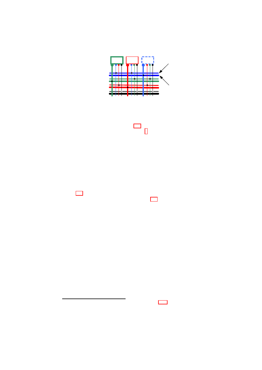
CHAPTER 4. AUTOMATED PROVISIONING OF SECURE VIRTUAL NETWORKS
47
vSwitch
Fabric
vMachines
& vPorts
FW
FW
FW
Interconnect
(Blue)
Internal
(Blue)
Figure 4.2: Internal- and Inter-connections for each TVD Type.
6. As shown by step 2 in Figure 4.4, a command is issued at the VM to join
the TVD (active membership model
6
). This results in the VM contacting
the TVD proxy. Based on the TVD security policies, the TVD proxy may
carry out an assurance assessment of the VM (e.g., whether the VM has all
required software properly configured). Once the required verification of the
VM is successful, the TVD proxy may connect the vNICs of the VM to the
appropriate TVD vSwitch. At this point, the VM is part of the TVD.
4.5
Auto-deployment of Trusted Virtual Domains)
Figure 4.3 shows the steps involved in automatic deployment of secure virtual in-
frastructures as TVD configurations. Figure 4.4 shows the steps involved in the
establishment and management of a single TVD.
First, the virtual infrastructure topology must be decomposed into constituent
TVDs, along with associated security requirements and policy model. Second,
a capability model of the physical infrastructure must be developed. Capability
modeling is essentially the step of taking stock of existing mechanisms that can be
directly used to satisfy the TVD security requirements. In this chapter, we consider
the case where both steps are done manually in an offline manner; future extensions
will focus on automating them and on dynamically changing the capability models
based on actual changes to the capabilities.
4.5.1
Capability Modeling of the Physical Infrastructure
Capability modeling of the physical infrastructure considers both functional and
security capabilities. The functional capabilities of a host may be modeled using
a function
C
:
H
→ {
V LAN, Ethernet, IP
}
, to describe whether a host has
VLAN, Ethernet, or IP support. Modeling of security capabilities includes two
6
Alternatively, if the passive membership model (Section 4.5.4) is used, the command to join the
TVD can be issued by the VM manager component that instantiates the VM.
OpenTC Document D05.5/V01 – Final R7343/2008/11/11/OpenTC Public (PU)

48
OpenTC D05.5 – Design and Concept of a Trusted Virtual Datacenter
orthogonal aspects: the set of security properties and the assurance that these prop-
erties are actually provided. Table 4.2 lists some examples of security properties
and Table 4.3 gives examples of the types of evidence that can be used to support
security property claims.
4.5.2
Instantiation of the Right Networking Modules
The TVD proxy uses the instructions given to it by the TVD master to determine
the right protection mechanisms to instantiate on the local platform for the TVD
network traffic, and accordingly configures the local TVD vSwitch.
Suppose that isolation of TVD traffic is a requirement. Then, VLAN tag-
ging alone would suffice provided the TVD spans only the LAN and the physical
switches on the LAN are VLAN-enabled (i.e., it must support IEEE 802.1Q and
must be appropriately configured); in that case, a VLAN tagging module would
be created and connected to the vSwitch. If the TVD spans beyond a LAN, then
VLAN tagging must be used in conjunction with EtherIP encapsulation. In this
case, the VLAN tagged packet is encapsulated in a new IP packet and tunneled to
the other side, where the original VLAN tagged packet is extracted and transmit-
ted on the VLAN. If VLAN-enabled switches are not available, then EtherIP alone
would suffice for isolation.
By itself, EtherIP does not provide integrity or confidentiality of the packets.
Hence, when those properties are required, EtherIP is suitable only on routed and
trusted networks, e.g., EtherIP would be suitable for traffic between two vSwitches
hosted on different physical platforms that are not connected to the same VLAN
switch in a datacenter or corporate environment.
If integrity or confidentiality are required properties and the underlying net-
work is not trusted, then IPsec is used in conjunction with EtherIP and VLAN. In
that case, the TVD proxy will create the VPN module, initialize it with the VPN
key obtained from the master, and connect it to the vSwitch. Since IPsec only
operates on IP packets and not Ethernet or VLAN ones, double encapsulation is
needed: EtherIP is used to first encapsulate the Ethernet or VLAN packets, fol-
lowed by IPsec encapsulation and encryption (using the VPN key).
4.5.3
Inter-TVD Management
Separation of flow control and transport. Transport part is based on today’s con-
nection between autonomous systems based on BGP. Flow control is based on fire-
walls. Flow control part figures out whether a packet can get out to the other TVD
and what protection mechanism is needed (e.g., encryption). After flow control,
border gateway takes care of routing the packet to the border gateway at other end.
Contact master for obtaining capability of the other side gateway. Master-master
communication for generating shared key for encryption for inter-TVD traffic.
One firewall for each other TVD, or new rules for another new TVD on the
same firewall?
OpenTC Document D05.5/V01 – Final R7343/2008/11/11/OpenTC Public (PU)

CHAPTER 4. AUTOMATED PROVISIONING OF SECURE VIRTUAL NETWORKS
49
Inter-TVD management deals with the interchange fabric for communication
between TVDs, enforcement of inter-TVD flow control policies, external zones (IP
versus Ethernet), approval of admission requests by TVD-external entities (such as
a new VM) to join the TVD, and linking such entities with the appropriate TVD
master.
Information flow control between TVDs has two aspects: physical topology
and policies. Physically, each TVD is implemented by at least two VLANs (Fig-
ure 4.2): an external VLAN and an internal VLAN. The external VLAN (shown in
Figure 4.2 by thin lines) serves as a backbone to send/receive information to/from
other TVDs. It is through the external VLAN that a TVD proxy communicates
with the TVD master before becoming a member of the TVD. The internal VLAN
(shown in Figure 4.2 by thick lines) connects machines that are part of a TVD.
Inter-TVD policies specify conditions under which VLANs belonging to differ-
ent TVDs are allowed to exchange information. The policies may be conveniently
represented by information flow control matrices, such as the one shown in Fig-
ure 4.1. For a given TVD, the policies are stored at the TVD master, which then
enforces them in a distributed fashion through admission control and appropriate
configuration of firewalls and TVD proxies.
Having separate VLANs for TVD-internal and TVD-external communication
facilitates unrestricted communication within a TVD and the complete isolation of
a TVD from another TVD if the inter-TVD policy specified allows no information
flow between the TVDs. Such is the case for
T V D
α
and
T V D
β
, according to the
flow control matrix shown in Figure 4.1.
A cheaper alternative to the dual VLAN solution would be to rely solely on
trusted boundary elements such as firewalls to enforce isolation. The resulting
assurance may be somewhat lower than that of the dual VLAN solution, because
of the possibility of mis-configuring the boundary elements.
As shown in Figure 4.1, inter-TVD communication can be broadly classified
into three types: (1) controlled connections, represented by policy entries in the
matrix, (2) open or unrestricted connections, represented by
1
elements in the ma-
trix, and (3) closed connections, represented by
0
elements in the matrix.
Controlled connections restrict the flow between TVDs based on specified poli-
cies. The policies are enforced at TVD boundaries (at both TVDs) by appropriately
configured firewalls (represented in Figure 4.2 by entities marked FW). The TVD
master may push pre-checked configurations (derived from TVD policies) into the
firewalls during the establishment of the TVD topology. If available, a management
console at the TVD master may be used to manually set up and/or alter the con-
figurations of the firewalls. A TVD firewall has multiple virtual network interface
cards, one card for the internal VLAN that the firewall protects and one additional
card for each TVD that the members of the protected TVD want to communicate
with.
Open connection between two TVDs means that any two machines in either
TVD can communicate freely. In such a case, the firewalls at both TVDs would
have virtual network cards for the peer domain and simply serve as bridges be-
OpenTC Document D05.5/V01 – Final R7343/2008/11/11/OpenTC Public (PU)
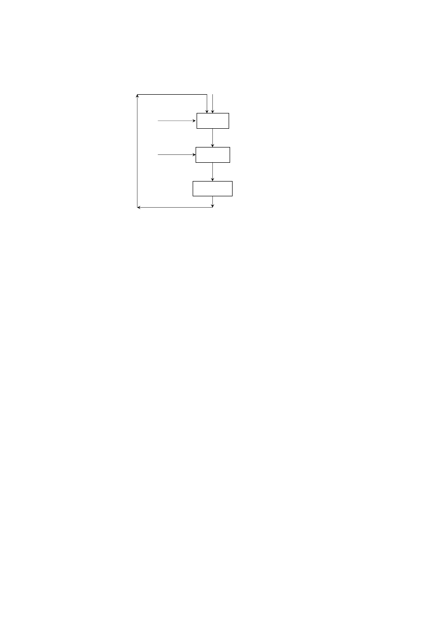
50
OpenTC D05.5 – Design and Concept of a Trusted Virtual Datacenter
Security
Policy
Per-host
Extensions
Global
Configuration
TVD
Requirements
Mechanisms
Required
Deployment Planning
& Management
TVD Policy
Model
Capability
Model
Revised Requirements,
Policies, or Capabilities
Figure 4.3: Steps in Auto-Deployment of TVDs.
tween the domains. For example, different zones in a given enterprise may form
different TVDs, but may communicate freely. As another example, two TVDs
may have different membership requirements, but may have an open connection
between their elements. Open connection between two domains may be imple-
mented using an unlimited number of virtual routers. In a physical machine that is
hosting two VMs belonging to different TVDs with an open connection, the cor-
responding vSwitches may be directly connected. Communication between two
TVDs, while open, may be subject to some constraints and monitoring. For ex-
ample, a TVD master may permit the creation of only a few virtual routers on
certain high-assurance physical machines for information flow between the TVD
and another TVD with which the former has an open connection.
A closed connection between two TVDs can be seen as a special case of a
controlled connection in which the firewall does not have virtual network card for
the peer TVD. In addition to the firewall filtering rules, the absence of the card will
prevent any communication with the peer TVD.
Special VMs (e.g., gateways) may have membership in two or more open
TVDs simultaneously. Consider a VM that is first a member of TVD
α
. The
VM has one virtual NIC that is connected to the vSwitch of TVD
α
. Now, suppose
that the VM needs to be a member of both TVD
α
and TVD
β
simultaneously. For
this purpose, the VM needs to have two virtual NICs, one connected to the vSwitch
of TVD
α
and the other connected to that of TVD
β
. Any VM request to create a
new virtual NIC has to be approved by the TVD proxy, which grants the approval
only if TVD
α
is an open TVD and TVD
α
’s policies allow such a dual member-
ship. Initially, the new virtual NIC is connected to the default network, and the
VM sends a membership request for TVD
β
to the local TVD proxy (if present) or
a remote TVD master. If TVD
β
’s policies allow for dual membership with TVD
OpenTC Document D05.5/V01 – Final R7343/2008/11/11/OpenTC Public (PU)

CHAPTER 4. AUTOMATED PROVISIONING OF SECURE VIRTUAL NETWORKS
51
α
and the VM satisfies other admission requirements for TVD
β
, then proxy for
TVD
β
will connect the new virtual NIC to the vSwitch of TVD
β
. At this point,
the VM is connected to the VLANs of both TVDs.
4.5.4
Intra-TVD Management
Intra-TVD management is concerned with TVD membership (including mutual
authentication), communication within a TVD, and the network fabric (i.e., inter-
nal topology) of a TVD. Prior to membership negotiation, mutual authentication
requires both the TVD infrastructure (TVD proxy or the master in the absence of
a proxy) and the client (i.e., the prospective member VM) to authenticate itself to
each other. For TVD authentication, we employ TVD certificates that are issued
and distributed for each TVD. For client authentication, we use the IEEE 802.1X
standard for network access control (NAC). The latter employs a port-based au-
thentication scheme and a third-party authenticator (e.g., a RADIUS server) to au-
thenticate the VM. In this setting, the TVD proxy acts as the authenticator that
forwards the request to the authentication server and interprets the result. We de-
scribe client authentication in detail in Sections 4.5 and 4.6.
Intra-TVD policies specify the membership requirements for each TVD, i.e.,
the conditions under which a VM is allowed to join the TVD. At a physical machine
hosting the VM, the requirements are enforced by the machine’s TVD proxy in
collaboration with networking elements (such as vSwitches) based on the policies
given to the TVD proxy by the TVD master. We describe TVD admission control
in detail in Section 4.5.
A VLAN can be part of at most one TVD. For completeness, each VLAN that
is not explicitly part of some TVD is assumed to be a member of a dummy TVD,
T V D
∆
. Although a VLAN that is part of
T V D
∆
may employ its own protection
mechanisms, the TVD itself does not enforce any flow control policy and has open
or unrestricted connections with other TVDs. Thus, in the information flow control
matrix representation, the entries for policies,
P
∆
α
and
P
α
∆
, would all be
1
for any
T V D
α
.
A VM that is connected to a particular VLAN segment automatically inherits
the segment’s TVD membership. The VM gets connected to the VLAN segment
only after the TVD proxy on the VM’s physical machine has checked whether the
VM satisfies the TVD membership requirements. Once it has become a member,
the VM can exchange information freely with all other VMs in the same VLAN
segment and TVD (intra-TVD communication is typically open or unrestricted).
As mentioned before, a VM can be connected to more than one VLAN (and hence,
be a member of more than one TVD) through a separate vNIC for each VLAN.
A VM can become a TVD member either in an active or in a passive fashion.
In the passive membership model, a VM can be (passively) assigned a TVD mem-
bership at the time of its creation by specifying in the VM’s start-up configuration
files which VLAN(s) the VM should be connected to. Alternatively, in the active
membership model, a VM can actively request TVD membership at a later stage
OpenTC Document D05.5/V01 – Final R7343/2008/11/11/OpenTC Public (PU)
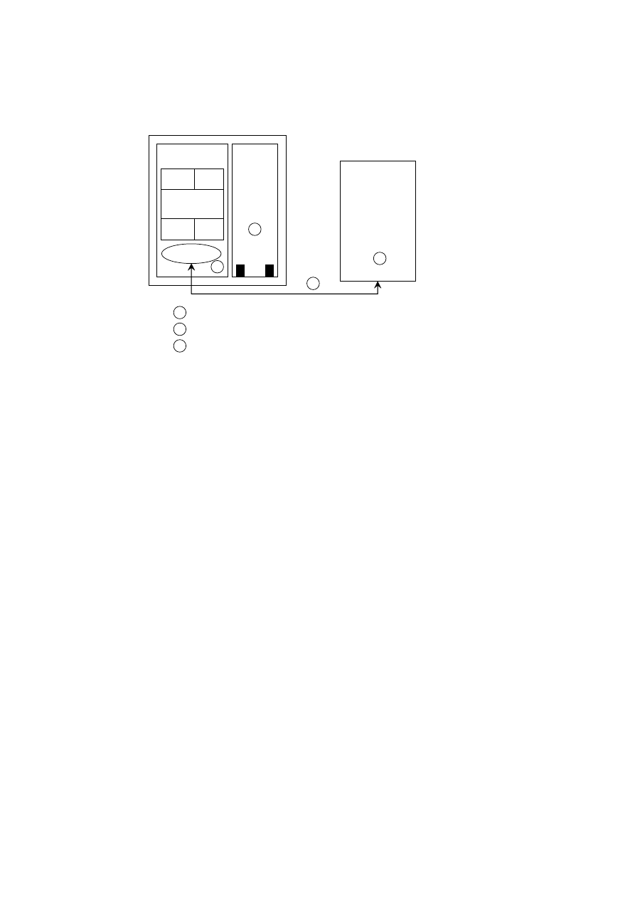
52
OpenTC D05.5 – Design and Concept of a Trusted Virtual Datacenter
TVD Master
DomU
Dom0
TVD proxy
TVD-specific
Modules
EtherIP VLAN
…..
Policy
Engine
TVD-specific
Modules
EtherIP VLAN
…..
Policy
Engine
vNICs
…
0
TVD object
←
create TVD (TVD requirements, policy model)
create TVD Proxy (Master URL)
1
0
2
connect VM to TVD (TVD object)
1
1
2
Figure 4.4: Steps in Populating a TVD.
through the corresponding TVD proxy interface or by directly contacting the TVD
master if a TVD proxy is not present on the local platform. When a VM is created,
it can use its default network connection to communicate with the outside world,
particularly the local TVD proxy (if present) or a remote TVD master to request
TVD membership. In either case, the IP address of the TVD authority must be
made available to the VM.
A closed TVD is a special TVD that has closed connections with all other
TVDs. For example, in a multi-level secure (MLS) military infrastructure, a top
secret military domain would be a good candidate for a closed TVD. A closed TVD
is shut off from the outside world, and a VM that does not belong to the TVD is
part of that outside world. Hence, the active membership model is not applicable
for closed TVDs. The TVD master for closed domains maintains a list of pre-
approved platforms and will create TVD proxies only on those platforms. Only the
system administrator or the TVD administrator can modify the list directly at the
TVD master.
Open TVDs are those that are not closed. Both active and passive membership
is possible in open TVDs. If the TVD master is directly contacted by the VM, the
master checks whether a TVD proxy is already present on the VM’s platform. If
so, the master instructs the proxy to initiate the admission protocol for the VM. If
the TVD proxy is not present, then the TVD master initiates the protocol with the
LCTC on the platform to create a TVD proxy.
TVD membership requirements may be checked and enforced on a one-time
or on a continual basis. Membership can be a one-time operation in which the
requirements are checked once and for all, and thereafter, the VM holds the TVD
OpenTC Document D05.5/V01 – Final R7343/2008/11/11/OpenTC Public (PU)

CHAPTER 4. AUTOMATED PROVISIONING OF SECURE VIRTUAL NETWORKS
53
membership for the duration of its life-cycle. Alternatively, membership require-
ments can be re-evaluated in an online fashion. The TVD proxy may regularly
check whether a VM satisfies the requirements. A session-based scheme may be
employed in which a VM is allowed open communication with other TVD mem-
bers only until the next check (i.e., end of the session).
Policy updates at the TVD master or updates to a platform configuration may
result in a platform becoming ineligible to any longer host member VPEs. In that
case, the TVD master contacts the LCTC and requests it to destroy the TVD proxy.
If the TVD is a closed TVD, prior to the actual destruction of the TVD proxy, mem-
bers VMs are either migrated to another platform with a TVD proxy or destroyed.
If the TVD is a open TVD, the VMs connected to the vSwitch are detached and
re-connected to the default network connection. The LCTC sends an acknowledg-
ment to the TVD master after the destruction of the TVD proxy. The TVD master
may also rekey the TVD VPN key and distribute the new VPN key to the TVD
proxies as a further security measure.
When a platform goes offline (e.g., due to maintenance or network partition),
the TVD proxy gets disconnected from the TVD master. In such cases, the discon-
nected TVD proxy still continues to act as the local TVD authority for the VMs
belonging to the TVD. However, the TVD VPEs on the platform are disconnected
from the rest of the TVD. The absence of a threshold number of status reports from
the TVD proxy causes the TVD master to update its list of TVD proxies. There-
after, when the platform comes online again, the LCTC on the platform contacts
the TVD master indicating that the disconnected platform is online again and con-
tains TVD VPEs that wish to re-connect to the rest of the TVD. That is followed
by a prepare phase, similar to the one that happens prior to the creation of the TVD
proxy (Section 4.4.2). It is necessary to re-assess the suitability of the platform for
still hosting the TVD proxy through the prepare phase, because the TVD policy and
the platform state may have changed in the duration when the platform was offline.
After the successful completion of the prepare phase, the TVD proxy re-establishes
the secure, authenticated communication channel with the TVD master. The TVD
proxy obtains the updated TVD policy and other credentials from the TVD master
through the channel, and re-configures the networking components according to
TVD policy.
4.6
Implementation in Xen
In this section, we describe a Xen-based [BDF
+
03] prototype implementation of
our secure virtual networking framework. Figure 4.5 shows the implementation of
two TVDs,
T V D
α
and
T V D
β
. The policy engine, also shown in the figure, im-
plements the policies corresponding to the TVDs specified in the information flow
control matrix of Figure 4.1, i.e., open connection within each TVD and closed
connection between
T V D
α
and
T V D
β
.
OpenTC Document D05.5/V01 – Final R7343/2008/11/11/OpenTC Public (PU)
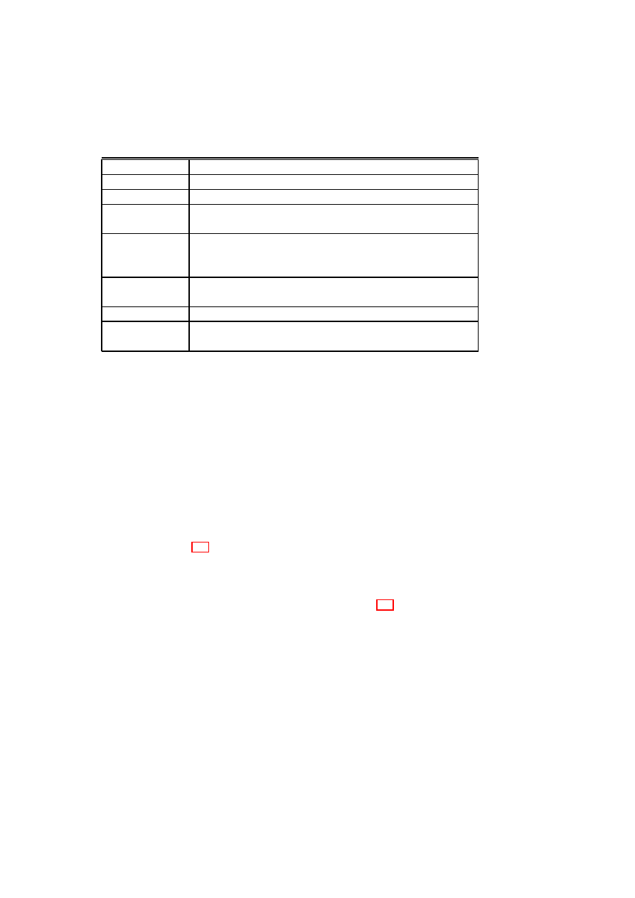
54
OpenTC D05.5 – Design and Concept of a Trusted Virtual Datacenter
Table 4.2: Examples of Security Properties used in Capability Modeling.
Property
Description
TVD Isolation
Flow control policies in place for a TVD.
Network
The actual topology of a virtual network in a physical machine.
Network Policy
Security policies for the network, such as firewall rules and isola-
tion rules stating which subnets can be connected.
Storage Policy
Policies for storage security, such as whether the disks are en-
crypted and what VMs have permission to mount a particular
disk.
Virtual Machines
The life-cycle protection mechanisms of the individual VMs, e.g.,
pre-conditions for execution of a VM.
Hypervisor
Binary integrity of the hypervisor.
Users
The roles and associated users of a machine, e.g., who can assume
the role of administrator of the TVD master.
4.6.1
Implementation Details
Our implementation is based on Xen-unstable 3.0.4, a VMM for the IA32 plat-
form, with the VMs running the Linux 2.6.18 operating system. Our networking
extensions are implemented as kernel modules in Dom0, which also acts as driver
domain for the physical NIC(s) of each physical host. A driver domain is special
in the sense that it has access to portions of the host’s physical hardware, such as a
physical NIC.
The virtual network interface organization of Xen splits a NIC driver into two
parts: a front-end driver and a back-end driver. A front-end driver is a special NIC
driver that resides within the kernel of the guest OS. It is responsible for allocating
a network device within the guest kernel (eth0 in Dom1 and Dom2 of hosts A and
B, shown in Figure 4.5). The guest kernel layers its IP stack on top of that device
as if it had a real Ethernet device driver to talk to. The back-end portion of the
network driver resides within the kernel of a separate driver domain (Dom0 in our
implementation) and creates a network device within the driver domain for every
front-end device in a guest domain that gets created. Figure 4.5 shows two of these
back-end devices, vif1.0 and vif2.0, in each of the two hosts A and B. These back-
end devices correspond to the eth0 devices in Dom1 and Dom2, respectively, in
each host.
Conceptually, the pair of front-end and back-end devices behaves as follows.
Packets sent out by the network stack running on top of the front-end network de-
vice in the guest domain appear as packets received by the back-end network device
in the driver domain. Similarly, packets sent out by the back-end network-device
by the driver domain appear to the network stack running within a guest domain
as packets received by the front-end network device. In its standard configuration,
Xen is configured to simply bridge the driver domain back-end devices onto the
real physical NIC. By this mechanism, packets generated by a guest domain find
OpenTC Document D05.5/V01 – Final R7343/2008/11/11/OpenTC Public (PU)
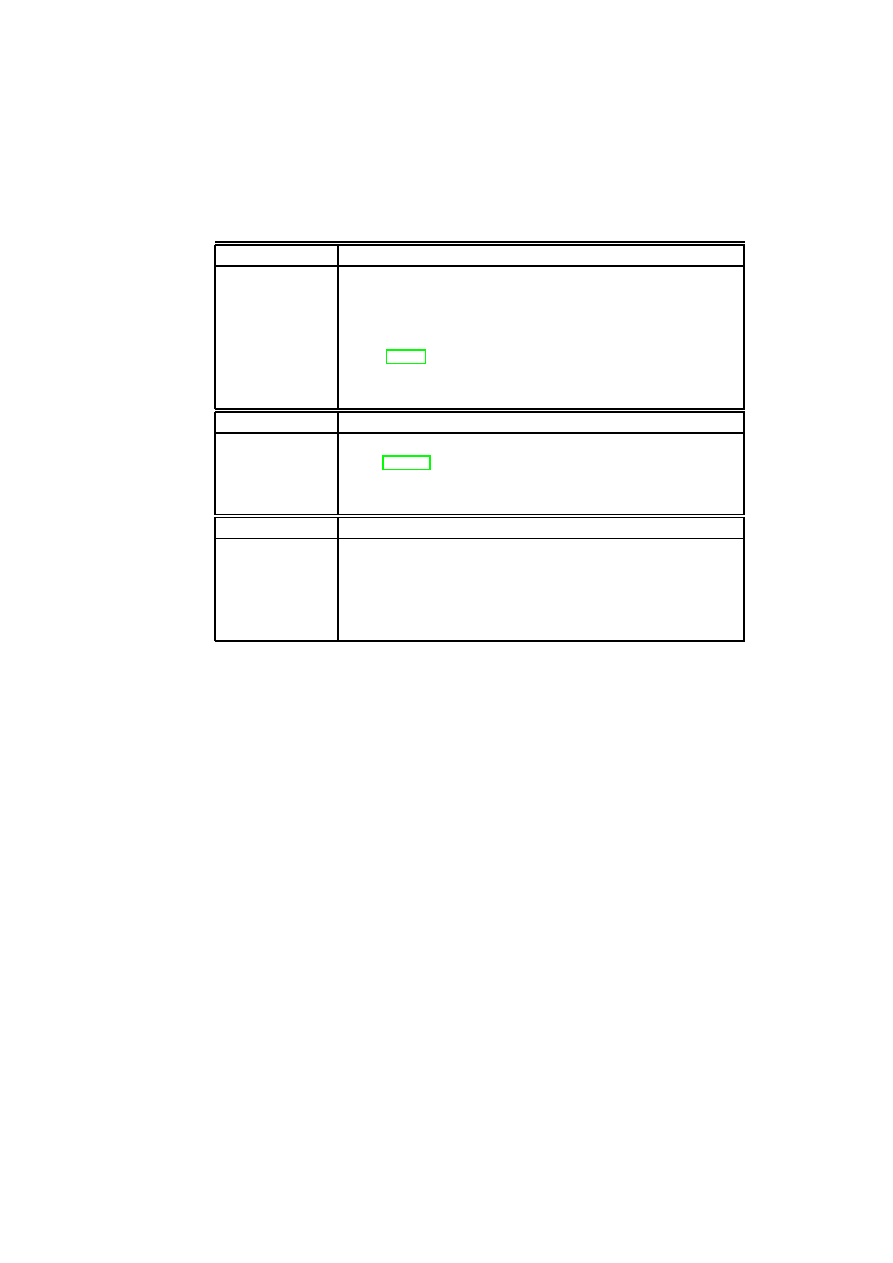
CHAPTER 4. AUTOMATED PROVISIONING OF SECURE VIRTUAL NETWORKS
55
Table 4.3: Assurance for Past, Present, and Future States used in Capability Mod-
eling.
Past State
Description
Trust
A user believes that an entity has certain security properties.
Mutable Log
The entity provides log-file evidence (e.g., audits) that indicates
that the platform provides certain properties.
Immutable Logs
The entity has immutable logging systems (e.g., a TPM-
quote [Tru03]) for providing evidence. Since the log cannot mod-
ified by the entity itself, the resulting assurance is stronger than
when mutable logs are used.
Present State
Description
Evaluations
Evaluation of a given state, e.g., Common Criteria evalua-
tions [Com98].
Introspection
Introspection of a system by executing security tests, e.g., virus
scanner.
Future State
Description
Policies
By providing policies and evidence of their enforcement, a system
can justify claims about its future behavior. e.g., DRM policies
and VM life-cycle protection policy.
Audit
By guaranteeing regular audits, organizations can claim that cer-
tain policies will be enforced in the future.
their way onto the physical network and packets on the physical network can be
received by the guest domain.
The Xen configuration file is used to specify the particular vSwitch and the
particular port in the vSwitch to which a Xen back-end device is attached. We
use additional scripts to specify whether a particular vSwitch should use one or
both of VLAN tagging and encapsulation mechanisms for isolating separate virtual
networks.
The vSwitches for
T V D
α
and
T V D
β
are each implemented in a distributed
fashion (i.e., spread across hosts A and B) by a kernel module in Dom0, which
maintains a table mapping virtual network devices to ports on a particular vSwitch.
Essentially, the kernel module implements EtherIP processing for packets coming
out of and destined for the VMs. Each virtual switch (and hence VLAN segment)
has a number identifier associated with it. The Ethernet packets sent by a VM
are captured by the kernel module implementing part of the vSwitch as they are
received on the corresponding back-end device in Dom0. The packets are encap-
sulated using EtherIP with the network identifier field set to match the identifier
of the vSwitch that the VM is supposed to be plugged into. The EtherIP packet
is given either a multicast or unicast IP address and simply fed into the Dom0
IP stack for routing onto the physical network. The kernel module also receives
EtherIP packets destined for the physical host. The module un-encapsulates the
OpenTC Document D05.5/V01 – Final R7343/2008/11/11/OpenTC Public (PU)
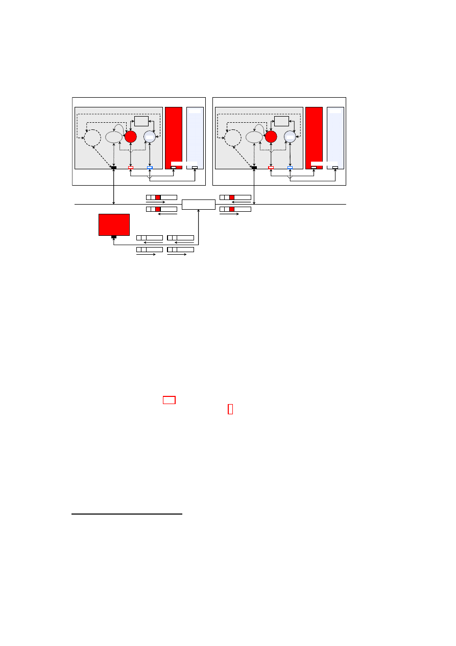
56
OpenTC D05.5 – Design and Concept of a Trusted Virtual Datacenter
Host A
Dom 1
Dom 0
α
encap.
module
VLAN
tagging
module
Policy
Engine
vSwitches
eth0
eth0
vif2.0
vif1.0
eth0
front-end devices
back-end
devices
physical
NIC
VLAN-capable
physical switch
Host B
Dom 1
Dom 0
α
encap.
module
VLAN
tagging
module
Policy
Engine
vSwitches
eth0
eth0
vif2.0
vif1.0
eth0
front-end devices
back-end
devices
physical
NIC
Host C
eth0
physical NIC
(VLAN un-aware)
C
A1
C
B1
C
A1
C
B1
A1
C
B1
C
A1
C
B1
C
Dom 2
Dom 2
β
β
Figure 4.5: Prototype Implementation of TVDs.
Ethernet frames contained in the encapsulated EtherIP packets and transmits the
raw frame over the appropriate virtual network interface so that it is received by
the intended guest vNIC.
In addition to the kernel module for EtherIP processing, we have also imple-
mented a kernel module for VLAN tagging in Dom0 of each virtualized host. Eth-
ernet packets sent by a VM are grabbed at the same point in the Dom0 network
stack as in the case of EtherIP processing. However, instead of wrapping the Eth-
ernet packets in an IP packet, the VLAN tagging module re-transmits the packets
unmodified into a pre-configured Linux VLAN device (eth0.
α
and eth0.
β
of hosts
A and B, shown in Figure 4.5) matching the VLAN that the VM’s vNIC is sup-
posed to be connected to. The VLAN device
7
(provided by the standard Linux
kernel VLAN support) applies the right VLAN tag to the packet before sending it
out onto the physical wire through the physical NIC. The VLAN tagging module
also intercepts VLAN packets arriving on the physical wire destined for a VM.
The module uses the standard Linux VLAN Ethernet packet handler provided by
the 8021q.ko kernel module with a slight modification: the handler removes the
VLAN tags and, based on the tag, maps packets to the appropriate vSwitch (
α
or
β
) which, in turn, maps them to the corresponding back-end device (vif1.0 or
vif2.0) in Dom0. The packets eventually arrive at the corresponding front-end de-
vice (eth0 in Dom1 or Dom2) as plain Ethernet packets.
7
An alternative approach, which we will implement in the future, is to directly tag the packet and
send the tagged packet straight out of the physical NIC without relying on the standard Linux VLAN
devices.
OpenTC Document D05.5/V01 – Final R7343/2008/11/11/OpenTC Public (PU)

CHAPTER 4. AUTOMATED PROVISIONING OF SECURE VIRTUAL NETWORKS
57
4.6.2
Implementation Issues
Below are some implementation issues we had to tackle in realizing the VLAN and
encapsulation approaches.
(1) Some Ethernet cards offer VLAN tag filtering and tag removal/offload capa-
bilities. Such capabilities are useful when running just a single kernel on a physical
platform, in which case there is no need to maintain the tags for making propa-
gation decisions. However, for our virtual networking extensions, the hardware
device should not strip the tags from packets on reception over the physical wire;
instead, the kernel modules we have implemented should decide to which VM
the packets should be forwarded. For this purpose, we modified the Linux kernel
tg3.ko and forcedeth.ko network drivers so as to disable VLAN offloading.
(2) For efficiency reasons, the Xen front-end and back-end driver implementa-
tions avoid computing checksums between them for TCP/IP and UDP/IP packets.
We modified the Xen code to also handle our EtherIP-encapsulated IP packets in a
similar manner.
(3) The EtherIP encapsulation approach relies on mapping a virtual Ethernet
broadcast domain to a IP multicast domain. While this works in a LAN environ-
ment, we encountered problems when creating VLAN segments that span WAN-
separated physical machines. We resolved this issue by building uni-directional
multicast tunnels between successive LAN segments.
4.7
Performance Results
We now describe performance results for the prototype implementation of our se-
cure virtual networking framework. We compare our results to Xen standard net-
working in bridging mode and also to non-virtualized systems.
4.7.1
Setup and Configuration
Our test systems run Xen 3.0.4 (release version) with a 2.6.18 Linux kernel in Do-
main 0. We used HP ProLiant BL25p G2 blade servers each fitted with two AMD
Opteron processors running at 2 GHz, 8GB system memory and a Gigabit Ethernet
card. We obtained the throughput results using the
NetPerf
network benchmark
and the latency results using the
ping
tool. Using the former benchmark, we mea-
sured the Tx (outgoing) and Rx (incoming) throughput for traffic from one guest
VM to another guest VM on the same physical host. To do so, we ran one instance
of the benchmark on one guest VM as a server process and another instance on the
second guest VM to do the actual benchmark.
4.7.2
Analysis
We report the throughput results for different networking schemes in Figure 4.6(a).
The graphs show that the throughput results for both VLAN tagging and EtherIP
OpenTC Document D05.5/V01 – Final R7343/2008/11/11/OpenTC Public (PU)
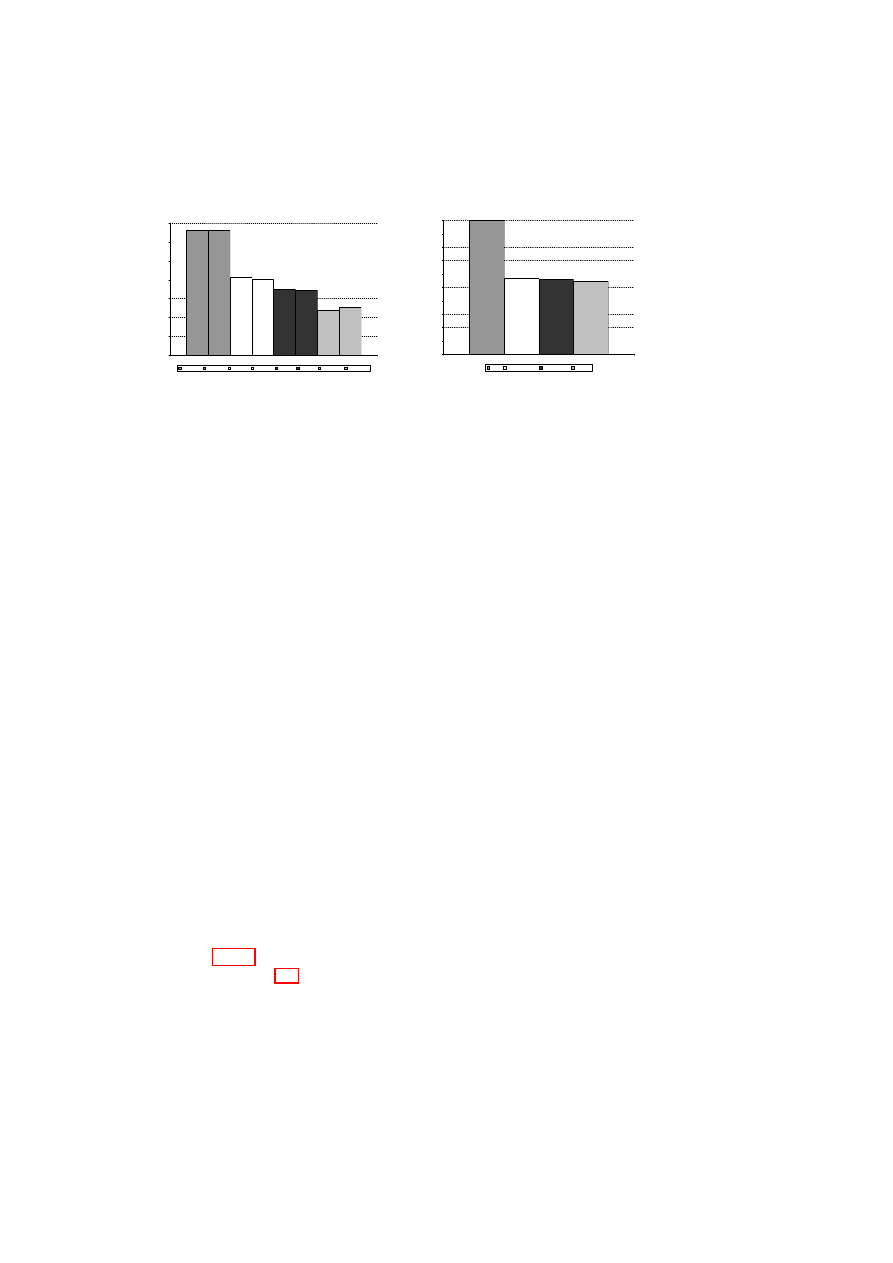
58
OpenTC D05.5 – Design and Concept of a Trusted Virtual Datacenter
800
820
840
860
880
900
920
940
1
T
h
ro
u
g
h
p
u
t
(M
b
p
s
)
LINUX TX
LINUX RX
VLAN TX
VLAN RX
BRG TX
BRG RX
EtherIP TX
EtherIP RX
(a) TX/RX throughput benchmark results.
100.00
55.98
54.69
56.79
0.00
10.00
20.00
30.00
40.00
50.00
60.00
70.00
80.00
90.00
100.00
1
T
h
ro
u
g
h
p
u
t
(%
)
Linux
VLAN Tagging
Xen Bridging
EtherIP
(b) Overhead of virtualization.
Figure 4.6: NetPerf Benchmark: Guest VM to Guest VM Throughput.
schemes are comparable to that of the standard Xen (bridge) configuration. Further,
VLAN tagging yields the best throughput in a virtualized system that outperforms
the standard Xen configuration. Both Xen bridging and VLAN tagging perform
better on the Tx path. For EtherIP, the major cost in the Tx path is having to
allocate a fresh socket buffer (
skb
) and copy the original buffer data into the fresh
skb
. When first allocating a
skb
, the Linux network stack allocates a fixed amount
of headroom for the expected headers that will be added to the packet as it goes
down the stack. Unfortunately, not enough space is allocated upfront to allow us
to fit in the EtherIP header; so, we have to copy the data around, which is very
costly. However, there is some spare headroom space, which is enough for the
extra VLAN tag. As a result, the VLAN tagging method does not suffer from the
packet copying overhead. The cost of copying data in the EtherIP case is greater
than the cost of traversing two network devices (the physical Ethernet device and
the Linux-provided VLAN device) for the VLAN packets. That is why the VLAN
method is more efficient than the EtherIP approach for the Tx path. In a future
version of our prototype, we will add a simple fix to the kernel to ensure that the
initial
skb
s have enough headroom upfront for the EtherIP header.
In the Rx path, there is no packet-copying overhead for the EtherIP approach;
the extra EtherIP header merely has to be removed before the packet is sent to a
VM. As compared to VLAN tagging, in which packets are grabbed from the Linux
network stack, EtherIP requires that packets are passed to and processed by the
host OS IP stack before they are handed over to the EtherIP packet handler of the
vSwitch code.
Figure 4.6(b) illustrates the overhead of virtualization technology on network
performance. Table 4.4 shows the round-trip times between two guest VMs on a
physical host for the bridged, VLAN, and EtherIP encapsulation cases obtained
using the
ping -c 1000 host
command, i.e., 1000 packets sent. The results
show that the average round-trip times for VLAN and EtherIP encapsulation are
17.8% and 36.7% higher than that of the standard Xen bridged configuration.
OpenTC Document D05.5/V01 – Final R7343/2008/11/11/OpenTC Public (PU)

CHAPTER 4. AUTOMATED PROVISIONING OF SECURE VIRTUAL NETWORKS
59
Table 4.4: Round-trip Times using Ping.
Minimum
Average
Maximum
Mean
Deviation
Bridged
0.136
0.180
0.294
0.024
VLAN
0.140
0.212
0.357
0.030
EtherIP
0.151
0.246
0.378
0.034
4.8
Discussion
In this chapter, we introduced a secure virtual networking model and a framework
for efficient and security-enhanced network virtualization. The key drivers of our
framework design were the security and management objectives of virtualized data
centers, which are meant to co-host IT infrastructures belonging to multiple de-
partments of an organization or even multiple organizations.
Our framework utilizes a combination of existing networking technologies
(such as Ethernet encapsulation, VLAN tagging, VPN, and NAC) and security
policy enforcement to concretely realize the abstraction of Trusted Virtual Do-
mains, which can be thought of as security-enhanced variants of virtualized net-
work zones. Policies are specified and enforced at the intra-TVD level (e.g., mem-
bership requirements) and inter-TVD level (e.g., information flow control).
Observing that manual configuration of virtual networks is usually error-prone,
our design is oriented towards automation. To orchestrate the TVD configuration
and deployment process, we introduced management entities called TVD masters.
Based on the capability models of the physical infrastructure that are given as input
to them, the TVD masters coordinate the set-up and population of TVDs using a
well-defined protocol.
We described a Xen-based prototype that implements a subset of our secure
network virtualization framework design. The performance of our virtual network-
ing extensions is comparable to the standard Xen (bridge) configuration.
OpenTC Document D05.5/V01 – Final R7343/2008/11/11/OpenTC Public (PU)

Chapter 5
Dependable and Secure Virtual
Datacenters
Bernhard Jansen, HariGovind V. Ramasamy, Matthias Schunter, and Axel
Tanner (IBM)
5.1
Introduction to Dependable Virtualization
In this chapter, we explore opportunities for dependability and security made avail-
able by virtualization, and provide detailed information on how virtualization af-
fects system reliability. We make four contributions: (1) a survey of dependability
and security enhancements enabled by virtualization, (2) a prototype demonstrat-
ing the effectiveness of hypervisor-based intrusion detection, (3) reliability models
and analysis of the effects of virtualization, and (4) an architecture for a reliability-
enhanced Xen VMM that leverages a subset of the enhancements.
We describe ways of leveraging virtualization for dependability and security
enhancements, such as response to load-induced failures, administration of patches
in an availability-preserving manner, enforcement of fail-safe behavior, proactive
software rejuvenation, and intrusion detection and protection. We describe in detail
a Xen-based implementation of a subset of these enhancements, particularly, intru-
sion detection and protection. The intrusion detector, called X-Spy, uses a privi-
leged Xen VM to monitor and analyze the complete state of other VMs co-located
on the same physical platform. X-Spy is close enough to the target monitored to
have a high degree of visibility into the innards of the target (like host-based in-
trusion detection schemes). At the same time, thanks to the isolation provided by
the VMM, X-Spy is far enough from the target to be unaffected even if the target
becomes compromised (like network-based intrusion detection schemes). A key
challenge in implementing X-Spy was the semantic gap, i.e., the proper interpre-
tation of process information gathered from the VMs monitored in a completely
different VM.
60
CHAPTER 5. DEPENDABLE AND SECURE VIRTUAL DATACENTERS
61
We provide detailed information on how virtualization affects an important
dependability attribute, namely reliability. The VMM is increasingly seen as a
convenient layer for implementing many services such as networking and secu-
rity [GR05] that were traditionally provided by the operating system. We show
why such designs should be viewed with more caution. We use combinatorial
modeling to analyze multiple design choices when a single physical server is used
to host multiple virtual servers and to quantify the reliability impact of virtualiza-
tion. In light of the prevailing trend to shift services out of the guest OS into the
virtualization layer, we show that this shift, if not done carefully, could adversely
affect system reliability.
We describe a reliability-enhanced Xen VMM architecture, called R-Xen, that
combines replication, intrusion detection, and rejuvenation. Normally, the Xen
VMM consists of a relatively small hypervisor core and a full-fledged privileged
VM called Dom0 that runs a guest OS (Linux). Regular VMs running on the
Xen VMM are called user domains or DomUs. Because of its size and complex-
ity, Dom0 is the weak point in the reliability of the Xen VMM. R-Xen focuses
on improving Dom0 reliability (and thereby improving the Xen VMM reliability)
through three-fold replication. The three Dom0 replicas each contain X-Spy im-
plementations to mutually monitor each other and thus detect the presence of faults
and/or intrusions in the other two. If two replicas report to the hypervisor that the
third is corrupted, the hypervisor terminates and rejuvenates the corrupt replica. If
the replica terminated happens to be the primary replica that provides device virtu-
alization for user domains, then one of the two backups becomes the new primary.
The remainder of the chapter is organized as follows. Section 5.2 describes
related work in the area of virtualization-based dependability and virtualization-
based intrusion detection. In Section 5.3, we describe at a high-level several de-
pendability and security enhancements (including intrusion detection and protec-
tion) that are made possible by virtualization. Section 5.4 describes X-Spy, our
Xen-based prototype implementation of intrusion detection and protection. Sec-
tion 5.5 analysis the reliability impact of virtualization and highlights the impor-
tance of VMM reliability to the overall reliability of a virtualized physical node.
Motivated by the conclusions of our reliability analysis and leveraging our X-
Spy implementation, Section 5.6 describes an architecture for a more reliable Xen
VMM.
5.2
Related Work
We now provide a sampling of related work in the area of using VMs for improv-
ing dependability. We also compare our X-Spy intrusion detection framework with
previous hypervisor-based intrusion detection systems. Many of these works, in-
cluding ours, implicitly trust the virtualization layer to function properly, to isolate
the VMs from each other, and to control the privileged access of certain VMs to
OpenTC Document D05.5/V01 – Final R7343/2008/11/11/OpenTC Public (PU)

62
OpenTC D05.5 – Design and Concept of a Trusted Virtual Datacenter
other VMs. Such a trust can be justified by the observation that a typical hyper-
visor consists of some tens of thousands lines-of-code (LOC), whereas a typical
operating system today is on the order of millions LOC [GR03]. This allows a
much higher assurance for the code of a hypervisor.
Bressoud and Schneider [BS96] implemented a primary-backup replication
protocol tolerant to benign faults at the VMM level. The protocol resolves non-
determinism by logging the results of all non-deterministic actions taken by the
primary and then applying the same results at the backups to maintain state consis-
tency.
Double-Take [VMw] uses hardware-based real-time synchronous replication
to replicate application data from multiple VMs to a single physical machine so
that the application can automatically fail over to a spare machine by importing the
replicated data in case of an outage. As the replication is done at the file system
level below the VM, the technique is guest-OS-agnostic. Such a design could pro-
vide the basis for a business model in which multiple client companies outsource
their disaster recovery capability to a disaster recovery hot-site that houses multiple
physical backup machines, one for each client.
Douceur and Howell [DH05] describe how VMMs can be used to ensure that
VMs satisfy determinism and thereby enable state machine replication at the VM
level rather than the application level. Specifically, they describe how a VM’s vir-
tual disk and clock can be made deterministic with respect to the VM’s execution.
The design relieves the application programmer of the burden of structuring the
application as a deterministic state machine. Their work is similar to Bressoud and
Schneider’s approach [BS96] of using a VMM to resolve non-determinism. How-
ever, the difference lies in the fact that whereas Bressoud and Schneider’s approach
resolves non-determinism using the results of the primary machine’s computation,
Douceur and Howell’s design resolves non-determinism a priori by constraining
the behavior of the computation.
Dunlap et al. describe ReVirt [DKC
+
02] for VM logging and replay. ReVirt
encapsulates the OS as a VM, logs non-deterministic events that affect the VM’s
execution, and uses the logged data to replay the VM’s execution later. Such a
capability is useful to recreate the effects of non-deterministic attacks, as they show
later in [JKDC05]. Their replay technique is to start from a checkpoint state and
then roll forward using the log to reach the desired state.
Joshi et al. [JKDC05] combine VM introspection with VM replay to analyze
whether a vulnerability was activated in a VM before a patch was applied. The
analysis is based on vulnerability-specific predicates provided by the patch writer.
After the patch has been applied, the same predicates can be used during the VM’s
normal execution to detect and respond to attacks.
Backtracker [KC03] can be used to identify which application running inside
a VM was exploited on a given host. Backtracker consists of an online component
that records OS objects (such as processes and files) and events (such as read, write,
and fork), and an offline component that generates graphs depicting the possible
chain of events between the point at which the exploit occurred and the point at
OpenTC Document D05.5/V01 – Final R7343/2008/11/11/OpenTC Public (PU)

CHAPTER 5. DEPENDABLE AND SECURE VIRTUAL DATACENTERS
63
which the exploit was detected.
An extension of Backtracker [KMLC05] has been used to track attacks from a
single host at which an infection has been detected to the originator of the attack
and to other hosts that were compromised from that host. The extension is based
on identifying causal relationships, and has also been used for correlating alerts
from multiple intrusion detection systems.
King et al. [KDC05] describe the concept of time-traveling virtual machines
(TTVMs), in which VM replay is used for low-overhead reverse debugging of
operating systems and for providing debugging operations such as reverse break
point, reverse watch point, and reverse single step. Combining efficient check-
pointing techniques with ReVirt, TTVMs can be used by programmers to go to a
particular point in the execution history of a given run of the OS. To recreate all
relevant state for that point, TTVMs log all sources of non-determinism.
Garfinkel and Rosenblum [GR03] introduced the idea of hypervisor-based in-
trusion detection, and pointed out the advantages of this approach and its applica-
bility not only for detection, but also for protection. Their Livewire system uses
a modified VMware workstation as hypervisor and implements various polling-
based and event-driven sensors. Compared with Livewire, our X-Spy system em-
ploys more extensive detection techniques (e.g., by checking not only processes,
but also kernel modules and file systems) and protection techniques (such as pre-
checking and white-listing of binaries, and kernel sealing) with an explicit focus
on rootkit detection. In addition, X-Spy enables easy forensic analysis.
Zhang et al. [ZvDJ
+
02] and Petroni et al. [NLPFMA04] use a secure copro-
cessor as the basis for checking the integrity of the OS kernel running on the main
processor. However, as the coprocessor can only read the memory of the machine
monitored, only polling-based intrusion detection is possible. In contrast, X-Spy
can perform both polling-based and event-driven intrusion detection. Specifically,
it can intercept and deny certain requested actions (such as suspicious system calls),
and therefore has the capability to not only detect but also protect.
Laureano et al. [LMJ04] employ behavior-based detection of anomalous sys-
tem call sequences after a learning phase in which “normal” system calls are iden-
tified. Processes with anomalous system call sequences are labeled suspicious.
For these processes, certain dangerous system calls will in turn be blocked. The
authors describe a prototype based on a type-II hypervisor, namely, User-Mode
Linux (UML) [Dik00].
The ISIS system of Litty [Lit05] is also based on UML. ISIS runs as a process
in the host operating system and detects intrusions in the guest operating system
by using the
ptrace
system call for instrumenting the guest UML kernel. Unlike
X-Spy, ISIS focuses mostly on intrusion detection and not protection.
Jiang et al. [JWX07] describe the VMwatcher system, in which host-based anti-
malware software is used to monitor a VM from within a different VM. X-Spy and
VMwatcher are similar in that both use the hypervisor as a bridge for cross-VM
inspection, and both tackle the semantic gap problem. While their work focuses on
bridging the semantic gap on a multitude of platforms (hypervisors and operating
OpenTC Document D05.5/V01 – Final R7343/2008/11/11/OpenTC Public (PU)

64
OpenTC D05.5 – Design and Concept of a Trusted Virtual Datacenter
systems), our work focuses on employing more extensive detection mechanisms
(such as checking not only processes, but also kernel modules, network connec-
tions, and file systems) on a single hypervisor. In contrast to X-Spy, VMwatcher
does not include event-driven detection methods or protection techniques.
The Strider GhostBuster system by Beck et al. [BVV05] is similar to X-Spy
in that both use a differential view of system resources. Strider GhostBuster com-
pares high-level information (such as information obtained by an OS command)
with low-level information (e.g., kernel information) to detect malicious software
trying to hide system resources from the user and administrator. However, such a
comparison has limited effectiveness as detection takes place in the same (poten-
tially compromised) OS environment. Beck et al. also compare the file system
view obtained from a potentially compromised OS with the view obtained from an
OS booted from a clean media. The disadvantage of such an approach is that it
requires multiple reboots and is limited to checking only persistent data (such as
file system) and not run-time data.
5.3
Using Virtualization for Dependability and Security
Commodity operating systems provide a level of dependability and security that is
much lower than what is desired. This situation has not changed much in the past
decade. Hence, the focus has shifted to designing dependable and secure systems
around the OS problems. Thanks to the flexible manner in which VM state can be
manipulated, virtualization can enable such designs. In particular, VM state, much
like files, can be read, copied, modified, saved, migrated, and restored [GR05]. In
this section, we give several examples of dependability and security enhancements
made possible by virtualization.
Coping with Load-Induced Failures: Deploying services on VMs instead of
physical machines enables a higher and more flexible resilience to load-induced
failures without requiring additional hardware. Under load conditions, the VMs
can be seamlessly migrated (using live migration [CFH
+
05]) to a lightly loaded
or a more powerful physical machine. VM creation is simple and cheap, much
like copying a file. In response to high-load conditions, it is much easier to dy-
namically provision additional VMs on under-utilized physical machines than to
provision additional physical machines. This flexibility usually compensates for
the additional resources (mainly memory) needed by the hypervisor.
Patch Application for High-Availability Services: Typically, patch applica-
tion involves a system restart, and thus negatively affects service availability. Con-
sider a service running inside a VM. Virtualization provides a way of removing
faults and vulnerabilities at run-time without affecting system availability. For this
purpose, a copy of the VM is instantiated, and the patch (be it OS-level or service-
level) is applied on the copy rather than on the original VM. Then, the copy is
restarted for the patch to take effect, after which the original VM is gracefully shut
OpenTC Document D05.5/V01 – Final R7343/2008/11/11/OpenTC Public (PU)

CHAPTER 5. DEPENDABLE AND SECURE VIRTUAL DATACENTERS
65
down and future service requests are directed to the copy VM. To ensure that there
are no undesirable side effects due to the patch application, the copy VM may be
placed under special watch for a sufficiently long time while its post-patch behav-
ior is being observed before the original VM is shut down. If the service running
inside the VM is stateful, then additional techniques based on a combination of
VM checkpointing (e.g., [AF02]) and VM live migration [CFH
+
05] may be used
to retain network connections of the original VM and to bring the copy up-to-date
with the last correct checkpoint.
Enforcing Fail-Safe Behavior and Virtual Patches: The average time be-
tween the point in time when a vulnerability is made public and a patch is available
is still measured in months. In 2005, Microsoft took an average time of 134.5 days
for issuing critical patches for Windows security problems reported to the com-
pany [Was06]. Developing patches for a software component is a time-consuming
process because of the need to ensure that the patch does not introduce new flaws
or affect the dependencies between the component involved and other components
in the system. In many cases, a service administrator simply does not have the lux-
ury of suspending a service immediately after a critical flaw (in the OS running the
service or the service itself) becomes publicized until the patch becomes available.
Virtualization can be used to prolong the availability of the service as much as
possible while at the same time ensuring that the service is fail-safe. We leverage
the observation that publicizing a flaw is usually accompanied by details of possible
attacks exploiting the flaw and/or symptoms of an exploited flaw. Developing an
external monitor to identify attack signatures or symptoms of an exploited flaw may
be done independently of patch development. The monitor may also be developed
much faster than the patch itself, because the monitor may not be subject to the
same stringent testing and validation requirements.
Consider a service running inside a VM rather than directly on a physical ma-
chine. Then, a VM-external monitor, running in parallel to the VM, can be used to
watch for these attack signatures or detect the symptoms of exploitation of the flaw.
If attack signatures are known, the VM-external monitor can be used to block the
attack, e.g. by filtering the incoming network stream, to terminate interaction with
the attack source, or to protect targeted structures inside the VM, e.g. the system
call table. If only symptoms of exploitation are known, detection of a compro-
mise can be used to immediately halt the VM. The monitor could be implemented
at the VMM level or in a privileged VM (such as Dom0 in Xen [BDF
+
03]). If
it is important to revert the service to its last correct state when a patch becomes
available, then the above technique can be augmented with a checkpointing mech-
anism that periodically checkpoints the state of the service with respect to the VM
(e.g., [AF02]).
Proactive Software Rejuvenation: Rebooting a machine is an easy way of
rejuvenating software. The downside of machine reboot is that the service is un-
available during the reboot process. The VMM is a convenient layer for introducing
hooks to proactively rejuvenate the guest OS and services running inside a VM in a
performance- and availability-preserving way [RK07]. Periodically, the VMM can
OpenTC Document D05.5/V01 – Final R7343/2008/11/11/OpenTC Public (PU)

66
OpenTC D05.5 – Design and Concept of a Trusted Virtual Datacenter
be made to instantiate a reincarnation VM from a clean VM image. The booting of
the reincarnation VM is done while the original VM continues regular operation,
thereby maintaining service availability. One can view this technique as a general-
ization of the proactive recovery technique for fault-tolerant replication proposed
by Reiser and Kapitza [RK07].
As mentioned above in the context of patch application, techniques based on
VM checkpointing and live migration may be used to seamlessly transfer network
connections and the service state of the original VM to the reincarnation VM. It
is possible to adjust the performance impact of the rejuvenation procedure on the
original VM’s performance. To lower the impact, the VMM can restrict the amount
of resources devoted to the booting of a reincarnation VM and compensate for the
restriction in resources by allowing more time for the reboot to complete.
One can view the above type of rejuvenation as a memory-scrubbing technique
for reclaiming leaked memory and recovering from memory errors of the original
VM. More importantly, such a periodic rejuvenation offers a way to proactively re-
cover from errors without requiring failure detection mechanisms (which are often
unreliable) to trigger the recovery.
Intrusion Detection and Response: Based on the location of the intrusion
detection sensors, intrusion detection system (IDS) implementations are broadly
classified into host-based IDS (HIDS) and network-based IDS (NIDS) [HDW00].
A NIDS monitors network traffic from and to the target, and analyzes the individual
packets for signs of intrusion. Because of its isolation from the target monitored, a
NIDS decreases its susceptibility to attacks and is largely unaffected by a compro-
mised target. However, as network traffic becomes increasingly encrypted and as
the NIDS has no direct knowledge of the effects or properties of the attack targets,
the usefulness of NIDS is decreased. The fact that not all intrusions may mani-
fest their effects in the form of malicious traffic also lowers the utility of NIDS.
The sensors of a HIDS are placed on the target machine itself, giving them a high
degree of visibility into the internals of the target, enabling closer monitoring and
analysis of the target than NIDS does. However, the location of HIDS on the same
“trust compartment” as the target is also a disadvantage: after an intrusion into the
target, the HIDS may no longer be trusted.
Virtualization provides a way of removing the disadvantages of HIDS and
NIDS, while retaining their advantages. In our approach, the sensors are placed
in a special privileged VM (called the secure service VM or SSVM) used for mon-
itoring other VMs hosting regular production services (called production VMs or
PVMs). The placement of the sensors on the same physical machine but in a dif-
ferent VM allows monitoring and analysis of the complete state of other VMs via
the VMM, and at the same time, keeps the sensor out of reach of a potentially
compromised VM and in a secure vantage position.
The twin characteristics of proximity to the target and isolation from the target
also make the SSVM a convenient location for implementing intrusion response
mechanisms. The secure vantage point of the SSVM allows one to implement
otherwise difficult responses, e.g., even a simple response like ‘shutdown a com-
OpenTC Document D05.5/V01 – Final R7343/2008/11/11/OpenTC Public (PU)

CHAPTER 5. DEPENDABLE AND SECURE VIRTUAL DATACENTERS
67
promised system’ may not be effectively triggered from inside the compromised
system. On the other hand, it is easy and effective to suspend the operations of a
compromised PVM from the SSVM. In addition, the SSVM can instruct the VMM
to provision a healthy replacement PVM or block suspicious system calls that may
potentially tamper with the integrity of the kernel.
For effective rejuvenation of a compromised PVM by re-provisioning a new
PVM, it is not sufficient to merely boot the new PVM from a clean state. The new
PVM might still possess all the vulnerabilities of the compromised one. Hence, it
is important to perform a forensic analysis of the compromised PVM’s state to re-
move as many vulnerabilities as possible. Such an analysis is facilitated by the vir-
tualized environment hosting the SSVM. The SSVM can obtain not only modified
files of a suspended PVM, but also its complete run-time state from the memory
dump created at the time of suspension. The memory dump can be examined using
the same techniques as the one used to observe the state of a running PVM from
the SSVM for the purpose of intrusion detection.
5.4
Xen-based Implementation of Intrusion Detection
and Protection
In this section, we describe the prototype implementation of a subset of the secu-
rity enhancements mentioned above, namely, intrusion detection and protection for
VMs. Later, in Section 5.6, we leverage the implementation for enforcing fail-safe
behavior and for triggering software rejuvenation in our construction of R-Xen.
5.4.1
Intrusion Detection and Protection for Xen Virtual Machines
We have implemented an intrusion detection and protection framework called X-
Spy. The core idea is to use a secure service VM (SSVM) that monitors one or
more production VMs (PVM). The SSVM performs the following functions:
Lie Detection The SSVM accesses the memory of the PVM and compares actual
critical system data (processes, mounts, etc.) against data obtained by ex-
ecuting normal Unix commands inside the PVM. If the comparison yields
discrepancies, then that is indicative of a compromised PVM. In contrast to
earlier hypervisor-based intrusion detection work, X-Spy’s detection mech-
anisms are more comprehensive and include lie detection at the level of pro-
cesses, network connections, modules, and file system mounts.
Protection We have added a system call inspector to Xen that allows the monitor-
ing of the system calls within the PVM for the purpose of protecting relevant
forensic information (like log files) and the integrity of the kernel (kernel
structures, modules, and memory).
OpenTC Document D05.5/V01 – Final R7343/2008/11/11/OpenTC Public (PU)

68
OpenTC D05.5 – Design and Concept of a Trusted Virtual Datacenter
X-Spy uses the Xen [BDF
+
03] VMM developed by Cambridge University and
guest VMs running the Linux 2.6 operating system. Nevertheless, the concepts
such as system call analysis and lie detection can be applied to other operating
systems such as Microsoft Windows. All X-Spy components are implemented
either in the Xen hypervisor or in the SSVM. While their implementation logic
depends on the guest OS, X-Spy does not require any modification to the guest OS
of the PVM.
Limitations
To overcome the semantic gap, we assume some knowledge of the kernel structures
of the guest operating system (specifically, Linux kernel 2.6) so that X-Spy com-
ponents can be appropriately coded. If the guest operating system is upgraded to a
newer version in which kernel structures are different, then the X-Spy components
need to be re-coded appropriately. That fact may be an impediment to commer-
cializing X-Spy, as it implies an ongoing commitment to develop and patch X-Spy
components to keep pace with upgrades to the guest operating system.
For detecting hidden processes, X-Spy requires that the scheduler of the PVM’s
guest OS keep a list of processes that need to be scheduled in a standard place
within a known memory structure. If an attacker is able to replace the scheduler
with her own one having a different list of processes, the detection approach would
be subverted. That is why it is important to protect the integrity of the kernel code
(for example, using mechanisms that we describe in Section 5.4.4).
The SSVM needs read access to the memory of the PVMs for the purpose
of monitoring them. In addition, it must be possible to do an SSH login to the
PVM from the SSVM and execute normal Unix commands. These requirements
are contrary to the isolation guarantees of the hypervisor. The SSVM itself could
become a high-value attack target, and accordingly, needs stronger protection. Sev-
eral measures can be taken to strongly reduce the potential of the SSVM getting
compromised. For example, as the SSVM is a special-purpose VM (in contrast to
PVMs), it can be hardened, its functionality reduced solely to that of monitoring
the PVMs, and its access restricted through a specific administrative interface.
5.4.2
Architecture of X-Spy
The architecture of the X-Spy intrusion detection framework is shown in Fig-
ure 5.1. Our architecture consists of a PVM and a SSVM running on top of the
same hardware and Xen hypervisor. In our implementation, both the SSVM and
the PVM run Linux kernel 2.6. The SSVM obtains the run-time state of the PVM
through the Xen hypervisor, which is at a lower level of abstraction than both the
SSVM and the PVM. The SSVM has access to the raw devices of the PVMs (mem-
ory, disk, network); however, the difficulty lies in the SSVM properly interpreting
OpenTC Document D05.5/V01 – Final R7343/2008/11/11/OpenTC Public (PU)
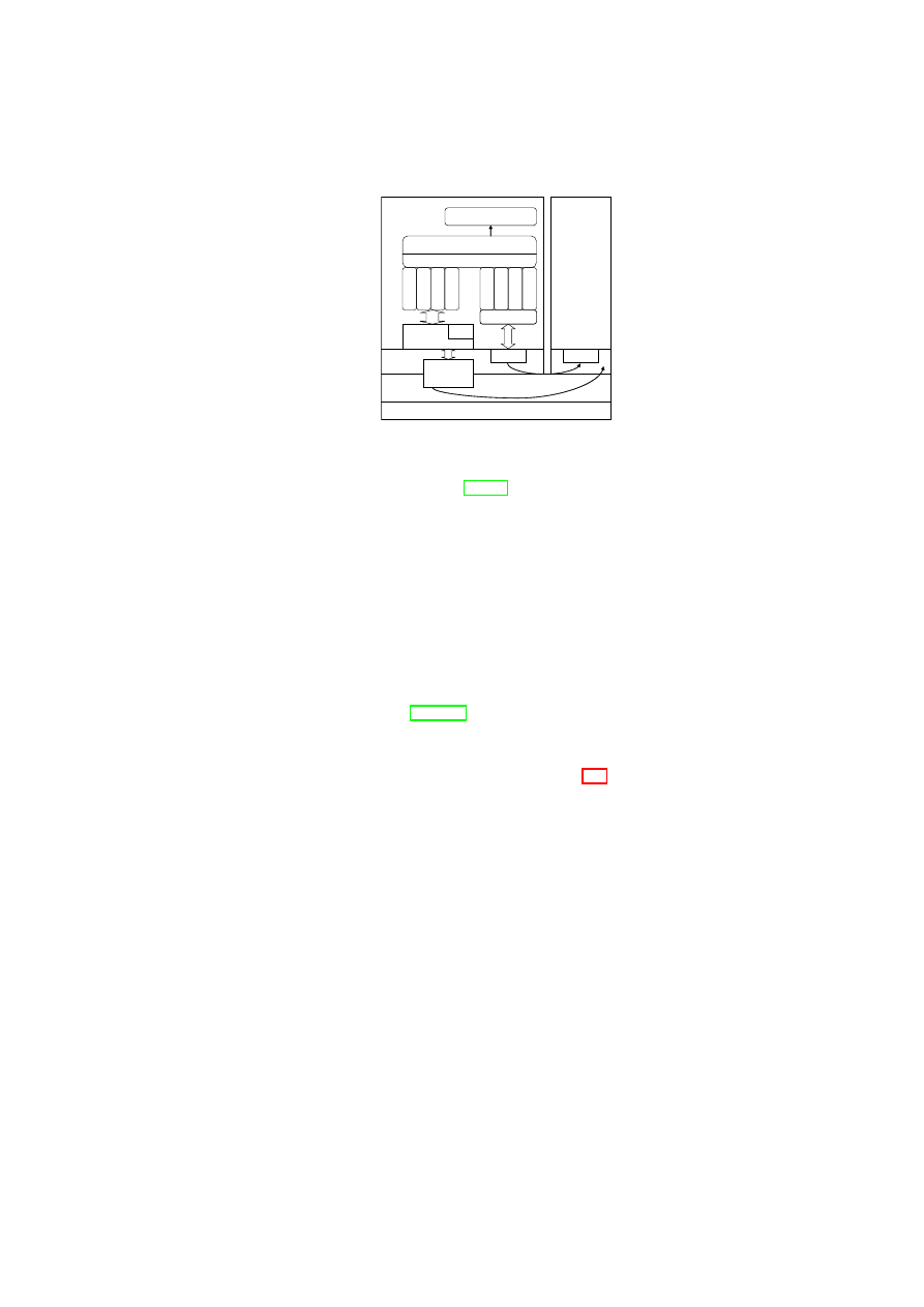
CHAPTER 5. DEPENDABLE AND SECURE VIRTUAL DATACENTERS
69
SSVM
PVM
N
C
R
L
P
L
L
M
L
L
M
o
L
L
PMT
GDMAL
n
e
ts
ta
t
p
s
ls
m
o
d
m
o
u
n
t
ssh
ssh
Lie - Detector
MTI
TCP/IP
TCP/IP
TCP/IP
TCP/IP
Normalizer
Kernel
Xen
User Space
Hardware
Event Handling
Figure 5.1: Architecture of the X-Spy Lie-Detector components.
the data because of a semantic gap [CN01]. For example, the physical memory of
the host system will be made available in chunks as pseudo-physical memory to
the VMs. In addition, the (possibly different) operating systems of the VMs use
a virtual address space on top of the physical memory, leading to the problem of
properly interpreting raw memory locations in a different context.
5.4.3
Intrusion Detection by means of a Lie-Detector
The basic idea of the Lie-Detector is to compare the insider and outsider views
of the system to identify objects (processes, files etc.) that try to hide themselves
from the operating system [BVV05]. Such behavior is typical of rootkits, which
are then used to hide other (typically malicious) software, but is also sometimes
characteristic of DRM functionality (e.g. the XCP content protection technology
by Sony BMG in 2005). The Lie-Detector (Figure 5.1) consists of three major
functionalities:
1. PVM Information Collection: The Lie-Detector collects information about
the PVM by two different means: the native interface and the frontDoor
interface.
2. PVM Information Normalization: The PVM information collected via the
native interface is normalized to a format equivalent to that of commands
executed through the frontDoor interface.
3. Analyze-and-Compare: The normalized information from the native and
frontDoor interfaces is then compared to identify differences that are indica-
tive of maliciously hidden system resources and to minimize false positives.
Any findings will be reported through the Event Handling component.
We describe the above functionalities in detail below.
OpenTC Document D05.5/V01 – Final R7343/2008/11/11/OpenTC Public (PU)

70
OpenTC D05.5 – Design and Concept of a Trusted Virtual Datacenter
Memory Translation Interface (MTI)
One of the main components of X-Spy
is a Memory Translation Interface (MTI) that allows the SSVM full access to a
PVM’s pseudo-physical and virtual memory in a convenient fashion. The MTI has
two parts:
1. An extension to the Xen hypervisor, which performs address translation and
traversal of the page tables.
2. A Linux kernel device driver that runs in the SSVM kernel and provides two
interfaces, namely,
/dev/mem_domX
and
/dev/kmem_domX
. These in-
terfaces are functionally equivalent to the
/dev/mem
and the
/dev/kmem
device files, respectively, and allow the root user in the SSVM kernel access
to the PVM’s physical memory and kernel memory contents, respectively.
One challenge to overcome when implementing the MTI was that the SSVM can-
not access a PVM’s foreign memory as it corresponds to a different context. There-
fore, the MTI has to emulate the memory management unit by translating the ad-
dress to the right format and re-mapping it from the PVM memory space onto the
memory space of the Lie-Detector process running in the SSVM. For this purpose,
we have developed two user-space libraries that the MTI uses: the Guest Domain
Memory Access Library or GDMAL and the Process Memory Translator or PMT.
The GDMAL provides read-write access to the PVM’s memory. Within the PVM’s
memory, the PMT allows access to the virtual address space of PVM processes.
In addition, the PMT provides some helper functions to facilitate the use of the
/dev/mem_domX
and
/dev/kmem_domX
interfaces. The PMT performs the
process address translation by extracting the memory management information for
the process from the OS-specific task (process) description data structure. When
the guest OS is Linux, as in our case, the PMT extracts the
mm_struct
data
structure from the
task_struct
data structure.
The native interface is used to collect PVM information “from the outside”
through the raw access made available by the Xen hypervisor, e.g. by accessing the
PVM’s memory via the MTI, and to collect host-specific data via special user-space
libraries that we have developed, namely the process list library (PLL), the network
connection and routing library (NCRL), and the module list library (MLL).
The second interface, called the frontDoor interface, is used to obtain PVM
information by doing an SSH login to the PVM and executing normal Unix com-
mands. The Lie-Detector normalizes the information collected from both inter-
faces, and then compares them. If the comparison yields discrepancies in the infor-
mation collected from those two sources, this is strongly indicative of an intrusion.
Obviously, it is not possible to obtain information through the frontDoor interface
and the native interface at exactly the same time. This timing difference may lead
to false positives, and we explain below how to overcome this problem. We im-
plement comparison methods for processes, network connections, kernel modules,
file system mounts and files.
OpenTC Document D05.5/V01 – Final R7343/2008/11/11/OpenTC Public (PU)

CHAPTER 5. DEPENDABLE AND SECURE VIRTUAL DATACENTERS
71
The MTI provides access to the PVM’s raw kernel virtual memory but lacks
any semantic context. To fix this shortcoming, we manually created a memory
offset file for each library
1
. Based on these files, the libraries such as PLL, NCRL,
and MLL, implement the logic to extract all data values of interest from the raw
kernel virtual memory. Each offset file stores the offset values of the start of each
data item of interest from the beginning of the containing structure.
Process List
The PLL acts on information provided by the MTI to generate out-
put similar to that of the
ps
command. This is done by accessing and then travers-
ing the doubly-linked circular task list via the MTI.
Our comparison is based on the multitude of information extractable from this
task_struct
data structure, such as PID, state, parent, open files, registers,
priorities, locks, and memory management information. However, not all fields in
the data structure are used. For example, the running time of a process as seen by
the native interface query and the frontDoor interface query are bound to slightly
differ, owing to the difference in the time of query.
This comparison will detect processes in the PVM that actively try to hide their
presence or change their appearance (e.g. the owner) from queries made from
within the PVM. This will identify rootkit-like behavior, as non-hiding processes
can be identified by more conventional (non-hypervisor-based) malware detection
tools.
Note that simply comparing the process information from the native and front-
Door interfaces results in false positives because of frequent changes to the process
table. We fix this by executing a native access (outsider view) before and after the
frontDoor query (insider view). If a given process disappeared in the second query
but is again visible in the third, we consider it to be an intrusion. If it does not
reappear, we assume that the process merely terminated.
Network Connections and Routing
We obtain information about IPv4 connec-
tions, Unix socket connections, and IPv4 routing through the native and frontDoor
interfaces. For the native interface queries, we have developed the NCRL library,
which uses the MTI to collect information equivalent to that obtained from three
commands: ‘
netstat -an -inet
’ for IPv4 connections, ‘
netstat -an
-unix
’ for Unix Socket connections, and ‘
netstat -rn
’ for IPv4 routing.
This information can then be used to discover hidden network connections.
Similar to the timing problem in the Lie-Detector comparison of process in-
formation, we face a timing problem in the comparison of network connection
information because of network connections that were terminated or started in the
time interval between the native interface query and the frontDoor interface query.
The solution here is again to reduce false positives by using three queries
2
.
1
With some effort, it is possible to generate the offset files automatically at kernel compilation
time.
2
Note that the frontDoor query is made through an SSH connection, which will show up only in
OpenTC Document D05.5/V01 – Final R7343/2008/11/11/OpenTC Public (PU)

72
OpenTC D05.5 – Design and Concept of a Trusted Virtual Datacenter
Module List
To obtain information about the PVM’s kernel modules we have
developed another user-space library called the MLL for collecting information
from the native interface query. The frontDoor interface query uses the
lsmod
command, which outputs the contents of
/proc/modules
displaying the kernel
modules currently loaded. In addition to the native interface and frontDoor inter-
face queries, the MLL also queries a third Xen interface for detecting hidden Linux
loadable kernel modules (LKMs). LKMs are a way to link object code without in-
terruption to the Linux kernel while it is running. Such LKMs are automatically
registered at loading time, but it is possible for an LKM to un-register itself af-
ter loading. In such a case, the LKM can hide even from a native interface query
(as the adore-ng rootkit indeed does; see Section 5.4.5). To address this issue,
we established a shadow module list in the hypervisor. The hypervisor traps the
init_module
system call and analyzes the ELF header section of the object file
to get the module name and stores the name in the shadow module list. The hy-
pervisor also traps the
delete_module
system call to remove entries from the
shadow module list. As the hypervisor address space cannot be accessed by the
PVM, the shadow module list cannot be altered by an intruder. The Xen interface
query shows the contents of the shadow module list and is taken as reference for
comparison with the results of the native interface and frontDoor interface queries.
If the results from the native interface and/or the frontDoor interface queries do not
list an entry from the shadow module list, we conclude that the module in question
is hidden.
Mounts
The frontDoor interface uses the
cat /proc/mounts
command,
which provides a list of all mounted file systems in the PVM. An obvious alter-
native would have been to use the output of the
mount
command; however that
alternative is less useful and secure because the command merely outputs the con-
tents of the
/etc/mtab
file, and it is easy to mount a file system without an entry
showing up in the
/etc/mtab
file by using the
mount -n
command.
The mount list library (MoLL
3
) operates on the PVM information about
mounted file systems collected via the native interface query. The starting sym-
bol for obtaining the information is the
task_struct
structure of the idle task
(however, the entry for any task would be adequate), from where the MoLL gains
access to the
vfsmnt
circular list. The list provides complete information about
all file systems currently mounted.
The mount information gathered from the native interface query is used as the
reference against which the information from the frontDoor interface is compared.
If there are mounted file systems that appear in the former but not in the latter, we
take this as an indication of a hidden malicious process because mount information
is relatively static, and hence false positives are not a big concern.
the frontDoor query but in neither of the interface queries.
3
The MoLL should not be confused with MLL, the module list library.
OpenTC Document D05.5/V01 – Final R7343/2008/11/11/OpenTC Public (PU)
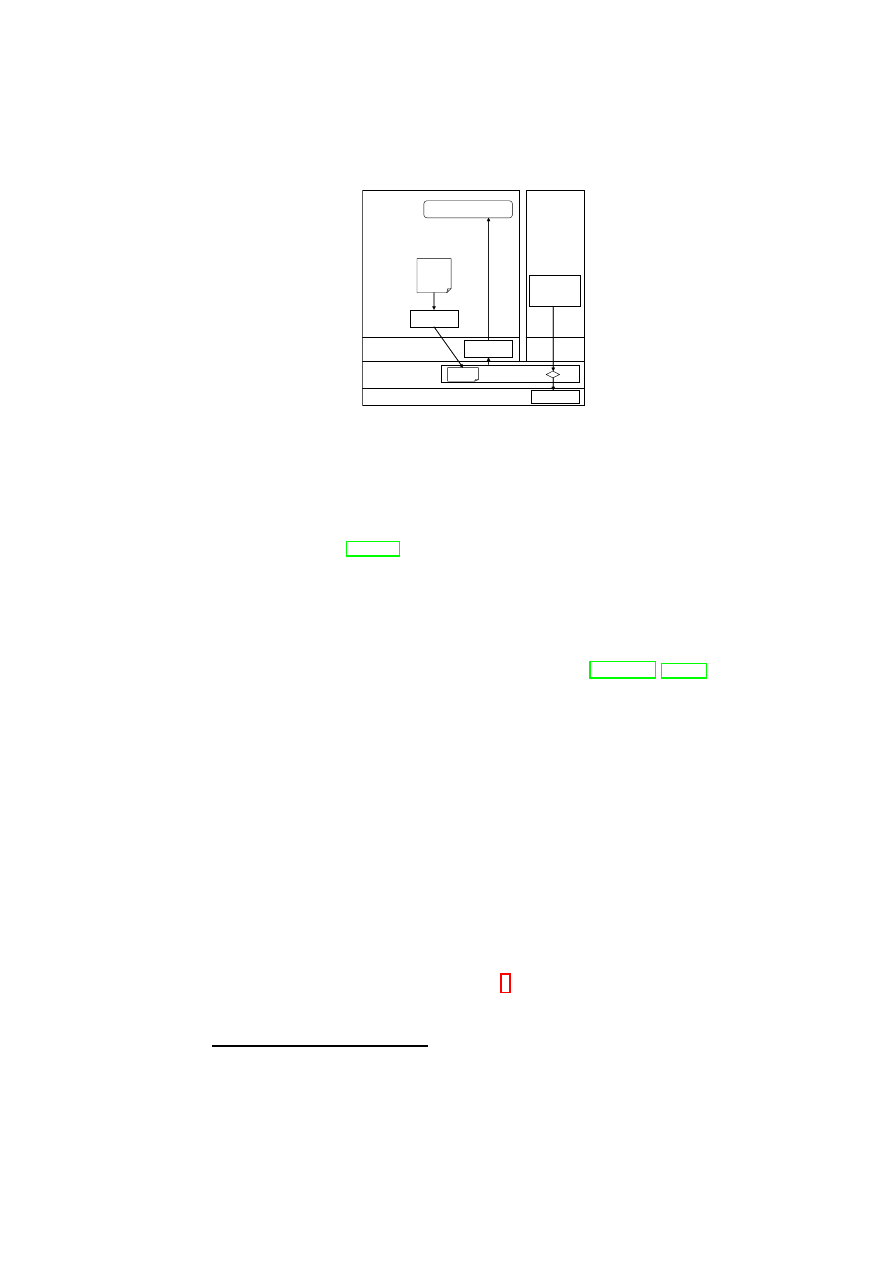
CHAPTER 5. DEPENDABLE AND SECURE VIRTUAL DATACENTERS
73
SSVM
PVM
EHKM
Kernel
Xen
User Space
Hardware
Event Handling
Rules
Application
CPU
SCI
Rules
PIT
system
calls
File system
In the case of the file system, bridging the semantic gap in general
implies the use of raw access to the physical disk and the related traffic to rebuild
the file system structures of the guest operating system of the PVM in the context of
the SSVM. Accessing file systems mounted by another operating system is feasible
even for disparate operating systems, e.g. Microsoft Windows and Linux, as for
example shown in [JWX07]. Xen can use a Linux file system existing on the
Xen/Dom0 level to boot and launch guest domains. This same file system can then
be mounted read-only by the SSVM. We then retrieve the file information via the
frontDoor and compare it with the information of the file system mounted by the
SSVM.
For efficiency and simplified forensic recording, we use a basic read-only file
system and add the CoWNFS copy-on-write file system [KMP
+
04, Ros08]. This
allows us to store the changes for multiple runs for later forensic analysis and
protects the original state of the system from any (potentially malicious) changes.
This combined file system was then used as an NFS mountable file system for
booting the PVM.
5.4.4
Protection of System Integrity and Forensic Information by
means of System Call Inspection
We now outline how X-Spy’s System Call Inspection component is used to protect
the system against intrusions.
Protection of Forensic Information
In case of a successful intrusion it is highly desirable to protect as much foren-
sic information as possible.
A smart intruder would want to hide all traces
of the intrusion, e.g., by altering log-files
4
such as the
wtmp/utmp
and the
/var/log/messages
files. While these files cannot be modified by normal
users, intruders with root access can. One way to address this issue would be to
4
Note that the above protection scheme for log files can easily be extended to protect other im-
portant files, such as Xen VM configuration files, through additional rules in the rule set.
OpenTC Document D05.5/V01 – Final R7343/2008/11/11/OpenTC Public (PU)

74
OpenTC D05.5 – Design and Concept of a Trusted Virtual Datacenter
use a hardened system (e.g., SELinux). However, this protects only if the superuser
is not allowed to change the SELinux rules in a running System.
In a virtualized environment as considered here, we have the possibility to
protect important files by intercepting the system call sequence in the PVM through
the Xen hypervisor. For this purpose, we added a module to the Xen hypervisor,
the System Call Inspector (SCI), which can inspect all
5
system calls occurring in
the PVM and either block or accept calls depending on a set of rules. These rules
are stored and edited in the SSVM (and therefore out of reach of any activity in the
PVM), and can be loaded into the SCI (in binary form) via the Policy Installation
Tool (PIT).
X-Spy implements a functionality for checking and fine-tuning system calls
by instrumenting the system call handling chain. An
int 0x80
instruction is
intercepted by an interrupt handler located in the Xen context where checks against
the previously introduced rule set are done. Only after passing the checks is the call
redirected to the PVM Kernel, where the normal system call handler is invoked;
otherwise, the call returns without any action being taken. In certain cases, the
system call is allowed after some fine-tuning, e.g., a modification of the parameters
so that the call conforms to the rule set specified. The amount of performance
overhead depends on the type of checks and fine-tuning being done for a particular
system call.
As the interception of the system call happens in the Xen context, the prob-
lem of semantic gap has to be overcome to determine which system calls actually
merit additional checks. For our aim of protecting forensic information, system
calls performing file operations are essential. We protect forensic information by
preventing calls that rename, link, unlink, or delete log files. Furthermore, we limit
access to log files by permitting only the append operation on them. To ensure that
a malicious process cannot bypass the checking, we normalized the paths.
If the SCI finds that an application in the PVM tries to initiate a system call that
is not allowed according to the rule set, it will block or modify it and send a corre-
sponding event through an event handling kernel module (EHKM) in the SSVM to
the high-level event handling component with information about the violated rule
and the corresponding process in the PVM.
Protection of Binaries against User-Space Rootkits
The mechanism used for protecting forensic information can also be used to protect
binaries from being altered by an intruder. Many user-space rootkits try to alter
ps
or
netstat
to hide their presence or to install a back door by modifying the
openssh
binary. While earlier tools, such as Tripwire, can detect the alteration
of a binary or a library, our event-driven approach to check system calls and their
arguments can actually prevent their alteration.
5
Note that Xen implements a “fast trap” mechanism to enhance performance. If Xen calls are to
be monitored as well, then this mechanism need to be disabled.
OpenTC Document D05.5/V01 – Final R7343/2008/11/11/OpenTC Public (PU)

CHAPTER 5. DEPENDABLE AND SECURE VIRTUAL DATACENTERS
75
In addition, it is possible to restrict read/write access to an executable, but still
allow its execution. Based on the corresponding rule set, the module we have im-
plemented in the Xen hypervisor checks whether a system call is trying to change,
delete, link, or rename a binary, and if so, the call is denied. As execution of a bi-
nary normally happens through the
execve
system call without actually opening
the binary file, it is even possible to add a rule that forbids the opening of certain
binaries completely without disallowing their execution.
Kernel Sealing
X-Spy also implements kernel sealing, a well-known method to protect a system
or prevent intrusions. The kernel memory can be accessed directly by reading
or, more dangerously, by writing to the
/dev/mem
or
/dev/kmem
device files.
The rule set of the X-Spy event-driven module in the Xen hypervisor was updated
to restrict access to those files, so that only read requests are allowed and write
requests return an error result without performing the write operation.
Accessing the kernel memory by loading a kernel module or writing directly
to /dev/(k)mem is potentially dangerous because it allows an intruder to establish
its own interface to the kernel; thereafter, the intruder can easily place malicious
code in the kernel and have full access to the file system and other kernel internals.
X-Spy uses a technique called white-listing by which all kernel modules allowed
to be loaded are explicitly specified along with their respective SHA-1 hash values.
If the module to be loaded at run-time is not specified in the white-list or if it
has an incorrect hash value, X-Spy prevents the module from being loaded by
preventing the system call from reaching the PVM kernel space. Note that our X-
Spy implementation does not offer protection against buffer overflows on systems
calls.
Pre-Checking of Binaries
An effective way of protecting a PVM from user-space rootkits or other malicious
software is to check the hash of every binary, prior to its execution, against a white-
list of pre-calculated hashes and to allow its execution only if there is a match.
Computing the hash of the binary has to be done out of the reach of a potential
intruder in the PVM and should also not require modification of the PVM’s OS.
To meet these conditions, X-Spy computes the hash of the binary in the SSVM.
To enable such a computation, it is necessary that the SSVM has all partitions
of the PVM mounted; furthermore, the binary should not be on a RAM disk, on
network file system, or on an encrypted file system that the SSVM cannot access.
An alternative would be to do the computation in the hypervisor, which would
require overcoming the semantic gap problem.
For computing the hash of the binary in the SSVM, we use a technique called
memory scanning, which involves loading the complete
.text
and
.data
sec-
tions of an ELF binary into memory by setting the program counter to the next
OpenTC Document D05.5/V01 – Final R7343/2008/11/11/OpenTC Public (PU)

76
OpenTC D05.5 – Design and Concept of a Trusted Virtual Datacenter
page, asking the PVM kernel to load the page, and then hashing it while handling
the page fault.
If the hash cannot be verified the hypervisor invalidates all of the memory and
returns the control back to the guest domain. Because of the invalid
.text
section
to which the PC points, the process will crash. Note that relying on support from
the PVM’s guest OS does not necessarily constitute a security gap, because a non-
cooperative PVM kernel would lead to a wrong hash value and in this case, as seen
above, the process will be forced to quit.
5.4.5
Evaluation
While the conceptual limitations have been discussed in Section 5.4.1, we will now
evaluate the effectiveness and efficiency of our implementation.
Functional Evaluation
The goal of the Lie-Detector is to expose malicious code. Once all information is
visible, we no longer focus on whether a particular LKM or process is hostile.
We first evaluated our implementation using a set of functional tests that im-
plement typical rootkit functionality, such as hiding processes, kernel modules,
mounts, or network connections. Our Lie-Detector correctly exposed all attempts
to hide such critical information.
We then tested the system using the adore-ng rootkit [ste01]. Adore-ng is an
LKM-based rootkit for Linux kernels which allows one to hide files and directo-
ries, processes, and network connections. The basic rootkit consists of the kernel
module and a user-space control program. While currently this is the only widely
available rootkit for the Linux kernel 2.6, other similar rootkits exist for earlier
kernel versions and may be ported to the 2.6 kernel.
In a fully protected X-Spy system, the rootkit cannot even be installed as the
insertion of modules is restricted through the SCI interception of the respective sys-
tem calls and the white-listing of allowed modules. After explicitly allowing the
rootkit to insert itself into the kernel, we used its control program to hide processes,
files, and network connections. The X-Spy Lie-Detector component reported these
hidden resources faithfully by comparing the responses from the native and front-
Door interfaces as described in Section 5.4.3. Although the adore-ng kernel mod-
ule will remove itself from the list of modules visible with
lsmod
, detection of
the module by the Lie-Detector is possible with the help of the shadow module list
(see discussion in Section 5.4.4).
The rule set used in X-Spy’s event-driven protection mechanism con-
tained about 110 rules, e.g.
to protect forensically relevant files (e.g.
/var/log/messages
and
/var/log/wtmp
) and
to prevent
access
to raw memory (
/dev/(k)mem)
,
security relevant configuration files
(
/etc/ssh.config
), and operating system tools (
/bin/ls
). In addition, we
specified an explicit list of allowed kernel modules (module white-listing). Once
OpenTC Document D05.5/V01 – Final R7343/2008/11/11/OpenTC Public (PU)
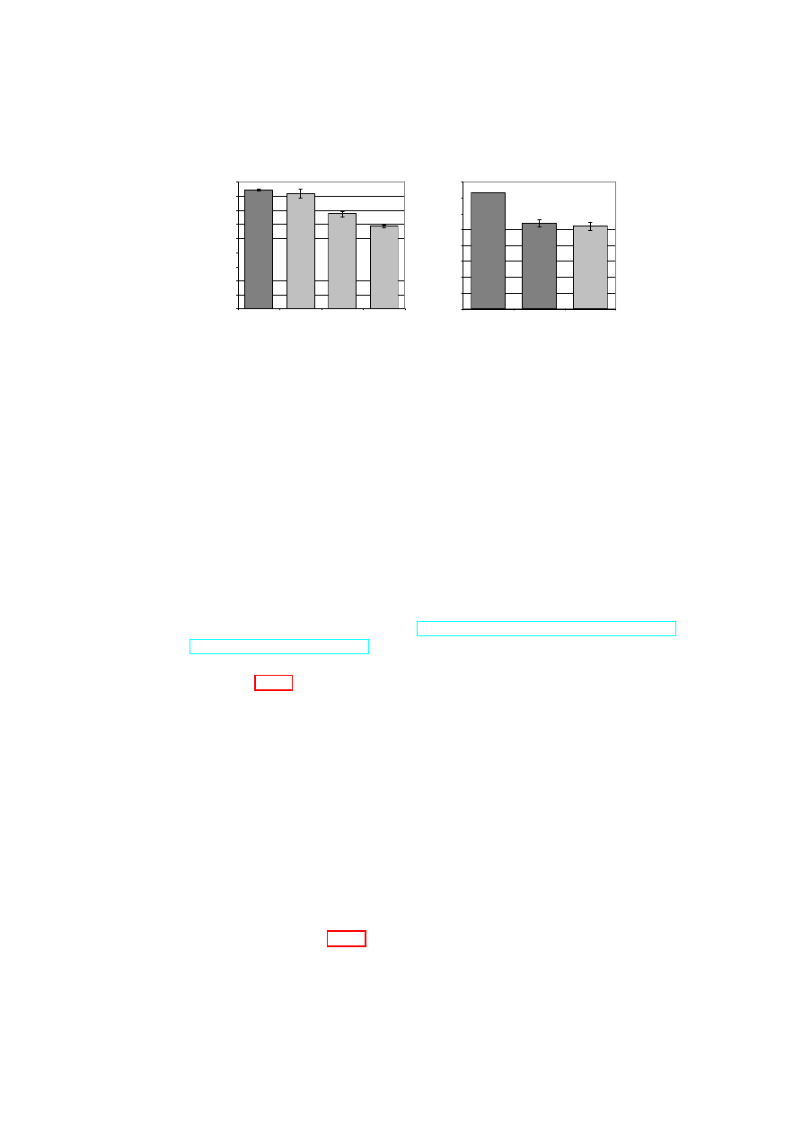
CHAPTER 5. DEPENDABLE AND SECURE VIRTUAL DATACENTERS
77
0
100
200
300
400
500
600
700
800
900
No Lie Detection
Lie Detection
every 30s
Lie Detection
every 10s
Lie Detection
continously
R
e
q
u
e
s
ts
/s
(a) Impact of Lie-Detector
0
100
200
300
400
500
600
700
800
Linux Native
Linux Xen Unmodified
Linux Xen w ith
Event-Driven
Detection
R
e
q
u
e
s
ts
/s
(b) Impact of protective measures
Figure 5.2: Performance impact of X-Spy components: number of fulfilled re-
quests per second in the HTTP benchmark.
the rule set was active, it either generated security events with information about
the offending processes in the PVM or successfully prevented the deletion or trun-
cation of log-files and the modification of configuration and utility files.
Performance Impact
To measure the performance impact of the Lie-Detector and the event-driven ap-
proach, we used a single machine implementing a web server scenario. The PVM
hosted an Apache web server, and multiple clients were simulated using the ab
performance benchmarking tool (see
http://httpd.apache.org/docs/
2.0/programs/ab.html
). The networks were virtual and internal to this ma-
chine.
Figure 5.2(a) shows that the performance impact of the Lie-Detector depends
on how often it is run. The overhead is roughly 31% when it is running continu-
ously, 20% when it is run every 10 sec, and 4% when it is run every 30 sec.
Most practical applications will run infrequent scans. In this case, the perfor-
mance impact of X-Spy is negligible, particularly when compared with the perfor-
mance reduction of moving Linux into a VM.
In a real-world setting, the frequency of “Lie Detection” should be chosen
based on the expected time until an intrusion occurs and the expected time until
such an intrusion is detected. The latter is an important factor because it denotes
the critical time window between the intrusion and its detection when the PVM is
at the mercy of the intruder, who can take arbitrary actions (such as installing a
fake website or copying private information onto a different system). If the PVM
runs a critical service in which the critical time window should be minimized, then
the Lie-Detector should be run continuously.
As seen in Figure 5.2(b), the event-driven method results in a performance
loss of about 4%. Compared with the 34% overhead incurred by changing from
OpenTC Document D05.5/V01 – Final R7343/2008/11/11/OpenTC Public (PU)

78
OpenTC D05.5 – Design and Concept of a Trusted Virtual Datacenter
a service running on a non-virtualized platform to that running on a Xen-based
PVM, the loss incurred by the event-driven approach is minor.
5.5
Quantifying the Impact of Virtualization on Node Re-
liability
In this section, we use combinatorial modeling to perform a reliability analysis
of redundant fault-tolerant designs involving virtualization on a single physical
node and compare them with the non-virtualized case. The results of the analysis
highlight the importance of improving the reliability of the hypervisor.
We consider a model in which multiple VMs run concurrently on the same
node and offer identical service. We derive lower bounds on the VMM reliability
and the number of VMs required for the virtualized node in order to have better
reliability than in the non-virtualized case. We also analyze the reliability impact
of moving a functionality common to all VMs out of the VMs and into the VMM.
In addition, we analyze the reliability of a redundant execution scheme that can
tolerate the corruption of one out of three VMs running on the same physical host,
and compare it with the non-virtualized case. Our results point to the need for
careful modeling and analysis before a design based on virtualization is used.
Combinatorial modeling and Markov modeling are the two main methods used
for reliability assessment of fault-tolerant designs [Joh89]. We chose combinatorial
modeling because its simplicity enables easy elimination of “hopeless” choices in
the early stage of the design process. In combinatorial modeling, a system consists
of series and parallel combinations of modules. The assumption is that module
failures are independent. In a real-world setting, where module failures may not be
independent, the reliability value obtained using combinatorial modeling should be
taken as an upper bound on the system reliability.
Non-Virtualized (NV) Node: For our reliability assessment, we consider a
non-virtualized single physical node as the base case. We model the node us-
ing two modules: hardware (
H
) and the software machine (
M
) consisting of the
operating system, middleware, and applications (Figure 5.3(a)) . Thus, the node
is a simple serial system consisting of
H
and
M
, whose reliability is given by
R
N V
sys
=
R
H
R
M
, where
R
X
denotes the reliability of module
X
(Figure 5.3(b)).
Virtualized Node with
n
Independent, Identical VMs: Figure 5.4(a) shows
a physical node consisting of
H
, a type-1 VMM (
V
) that runs directly on the
hardware (such a VMM is referred to as a hypervisor), and one or more VMs
(
{
M
i
}
, i
≥
1
). The VMs provide identical service concurrently and independently
(i.e., without the need for strong synchronization). For example, each VM could be
a virtual server answering client requests for static web content. Thus, the node is a
series-parallel system (Figure 5.4(b)) whose overall reliability is given by
R
n
sys
=
R
H
R
V
[1
−
Q
n
i
=0
(1
−
R
M
i
)]
. Here, we consider the reliability of the hardware to be
the same as that in the non-virtualized case because the underlying hardware is the
same in both cases. An obvious concern is whether the hardware in the virtualized
OpenTC Document D05.5/V01 – Final R7343/2008/11/11/OpenTC Public (PU)
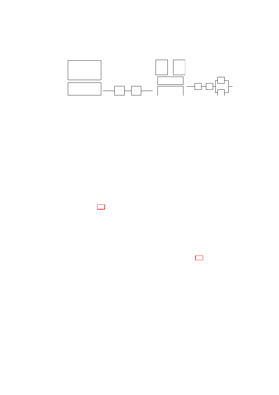
CHAPTER 5. DEPENDABLE AND SECURE VIRTUAL DATACENTERS
79
Hardware H
OS + Application
M
(a) Architecture
H
M
(b) Combinatorial Model
Figure 5.3: Non-virtualized node
. . .
Hardware H
Virtual
Machine
M
n
Virtual
Machine
M
1
Virtual Machine
Monitor V
(a) Architecture
n
M
M
.
.
.
H
V
1
(b) Combinatorial Model
Figure 5.4: Node with
n
VMs
node will register a significant drop in reliability due to load/stress compared with
the non-virtualized node. However, this concern does not apply to our context of
application servers in a data center, in which typical hardware utilization in a non-
virtualized node is abysmally low (less than 5%) and
n
is typically in the low tens
of VMs.
The condition for the
n
-replicated service to be more reliable than the non-
virtualized service is given by
R
n
sys
> R
N V
sys
. i.e.,
R
H
R
V
[1
−
Q
n
i
=0
(1
−
R
M
i
)]
>
R
H
R
M
. For simplicity, let
R
M
i
=
R
M
for all
1
≤
i
≤
n
. This is a reasonable
assumption, as each VM has the same functionality as the software machine
M
in
the non-virtualized case. Then, the above condition becomes
R
V
[1
−
(1
−
R
M
)
n
]
> R
M
.
(5.1)
Inequality (5.1) immediately yields two conclusions. First, if
n
= 1
, then again
the above condition does not hold (
R
V
<
1
). What this means is that it is necessary
to have some additional coordination mechanism or protocol built into the system
to compensate for the reliability lost by the introduction of the hypervisor. In the
absence of such a mechanism/protocol, simply adding a hypervisor layer to a node
will only decrease node reliability. Second, if
R
V
=
R
M
, then it is obvious that
above condition does not hold.
It is clear that the hypervisor has to be more reliable than the individual VMs.
The interesting question is how much more reliable. Figure 5.5 shows that for
a fixed
R
M
value, the hypervisor has to be more reliable when deploying fewer
VMs. The graph also shows that, for fixed values of
R
M
and
R
V
, there exists a
lower bound on
n
below which the virtualized node reliability will definitely be
lower than that of a non-virtualized node. For example, when
R
M
= 0.1 and
R
V
= 0.3, deploying fewer than 4 VMs would only lower the node reliability. This
is a useful result, as in many practical settings,
R
M
and
R
V
values may be fixed,
e.g., when the hypervisor, guest OS, and application are commercial off-the-shelf
(COTS) components with no source-code access.
The equation for
R
n
sys
also suggests that by increasing the number of VMs,
the node reliability can be made as close to the hypervisor reliability as desired.
Suppose we desire the node reliability to be
R
, where
R < R
V
. Then,
R
=
R
H
R
V
[1
−
(1
−
R
M
)
n
]
. Assume that the hardware is highly reliable, i.e.,
R
H
≃
1
.
OpenTC Document D05.5/V01 – Final R7343/2008/11/11/OpenTC Public (PU)
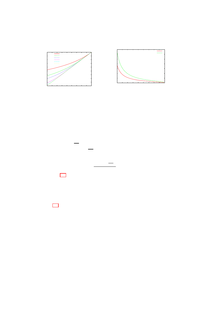
80
OpenTC D05.5 – Design and Concept of a Trusted Virtual Datacenter
0.1
0.2
0.3
0.4
0.5
0.6
0.7
0.8
0.9
1
0.1 0.2 0.3 0.4 0.5 0.6 0.7 0.8 0.9
1
Lower Bound on Reliability
of Hypervisor (R
V
)
Reliability of Virtual Machine (R
M
)
n=2
n=3
n=4
n=8
n=16
n=32
Figure 5.5:
Lower bound on the
hypervisor reliability for a physical
node with
n
independent and con-
currently operating VMs providing
identical service.
0
10
20
30
40
50
60
70
0.1
0.2
0.3
0.4
0.5
0.6
0.7
0.8
0.9
1
Lower Bound on Number of VMs (n)
Reliability of Virtual Machine (R
M
)
R = 0.98
R = 0.998
Figure 5.6: Lower bound on the num-
ber of VMs to achieve desired relia-
bility
R
for a physical node with
n
independent and concurrently operat-
ing VMs providing identical service
when
R
V
= 0
.
999
.
Then, the above equation becomes the inequality,
R < R
V
[1
−
(1
−
R
M
)
n
]
=
⇒
(1
−
R
M
)
n
<
1
−
R
R
V
=
⇒
n.
log(1
−
R
M
)
<
log(1
−
R
R
V
)
Dividing by
log(1
−
R
M
)
, a negative number, we obtain,
n >
log(1
−
R
R
V
)
log(1
−
R
M
)
.
(5.2)
Inequality (5.2) gives a lower bound on the number of VMs required for a
virtualized physical node to meet a given reliability requirement. In practice, the
number of VMs that can be hosted on a physical node is ultimately limited by the
resources available on that node. Comparing the lower bound with the number of
VMs that can possibly be co-hosted provides an easy way of eliminating certain
choices early in the design process.
Figure 5.6 shows the lower bound for
n
for two different
R
values (0.98 and
0.998) as the VM reliability (
R
M
) is increased from roughly 0.1 to 1.0, with the
hypervisor reliability fixed at
0
.
999
. The figure shows that for fixed
R
V
and
R
M
values, a higher system reliability (up to
R
V
) can be obtained by increasing the
number of VMs hosted. However, when
n
is large, one is faced with the practical
difficulty of obtaining sufficient diversity to ensure that VM failures are indepen-
dent.
Moving Functionality out of the VMs into the Hypervisor: We now ana-
lyze the reliability impact of moving a functionality out of the VMs and into the
hypervisor. As before, our system model is one in which a physical node has
n
≥
1
independent and concurrently operating VMs providing identical service.
Consider a functionality
f
implemented inside each VM. Then, each VM
M
i
can
be divided into two components,
f
and
M
′
i
, the latter representing the rest of
M
i
.
OpenTC Document D05.5/V01 – Final R7343/2008/11/11/OpenTC Public (PU)
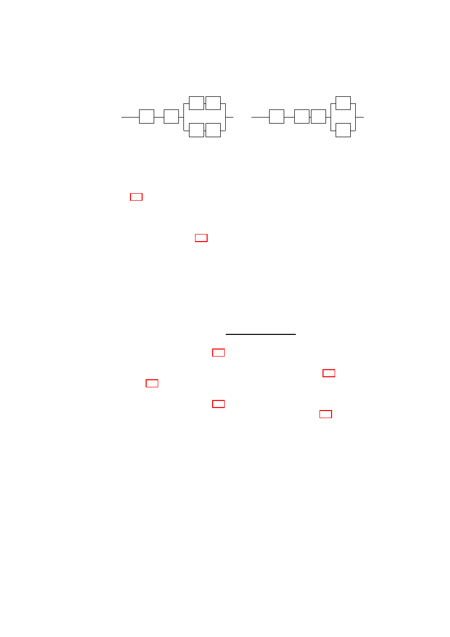
CHAPTER 5. DEPENDABLE AND SECURE VIRTUAL DATACENTERS
81
’
M
1
.
.
.
H
V
f
f
M
n
’
(a) Configuration
C
1
: Functionality
f
implemented within each VM
’
M
1
.
.
.
H
V
M
n
F
’
(b) Configuration
C
2
: Functionality
F
implemented as part of Hypervisor
Figure 5.7: Moving functionality out of the VMs into the hypervisor
Figure 5.7(a) shows the reliability model for a node containing
n
such VMs. Let
us call this node configuration
C
1
. Further, suppose that the functionality
f
is
moved out of the VMs and substituted by component
F
implemented as part of
the hypervisor. Now, the new hypervisor consists of two components
F
and the
old hypervisor
V
. Figure 5.7(b) shows the reliability model for a node with the
modified hypervisor. Let us call this node configuration
C
2
.
We now derive the condition for
C
2
to be at least as reliable as
C
1
. For simplic-
ity, let us assume that
R
M
′
i
=
R
M
′
for all
1
≤
i
≤
n
. Then, the desired condition
is
R
C
2
sys
≥
R
C
1
sys
=
⇒
R
H
R
V
R
F
[1
−
(1
−
R
M
′
)
n
]
≥
R
H
R
V
[1
−
(1
−
R
f
R
M
′
)
n
]
=
⇒
R
F
≥
[1
−
(1
−
R
f
R
M
′
)
n
]
[1
−
(1
−
R
M
′
)
n
]
.
(5.3)
It is easy to see from Figure 5.7 that if there is only one VM, it does not matter
whether the functionality is implemented in the hypervisor or in the VM. We can
also confirm this observation by substituting
n
= 1
in inequality (5.3).
Figures 5.8(a) and (b) illustrate how
R
F
varies as
R
f
is increased from 0.1 to
1. The graphs show that for configuration
C
2
to be more reliable than
C
1
,
F
has to
be more reliable than
f
. Figure 5.8(a) shows that as
R
M
′
increases, the degree by
which
F
should be more reliable than
f
also increases. Figure 5.8(b) shows that
the degree is also considerably higher when more VMs are co-hosted on the same
physical host. For example, even with modest
R
M
′
and
R
f
values of 0.75,
F
has
to be ultra-reliable:
R
F
has to be more than 0.9932 and 0.9994 if
n
= 6
and
n
= 9
,
respectively. Thus, when more than a handful of VMs are co-hosted on the same
physical node, a better system reliability is more likely to be obtained by retaining
a poorly reliable functionality in the VM rather than by moving the functionality
into the hypervisor.
Virtualized Node with VMM-level Voting: Consider a fault-tolerant 2-out-
of-3 replication scheme in which three VMs providing identical service are co-
hosted on a single physical node. The VMM layer receives client requests and
forwards them to all three VMs in the same order. Assume that the service is a
deterministic state machine; thus, the VM replicas yield the same result for the
OpenTC Document D05.5/V01 – Final R7343/2008/11/11/OpenTC Public (PU)
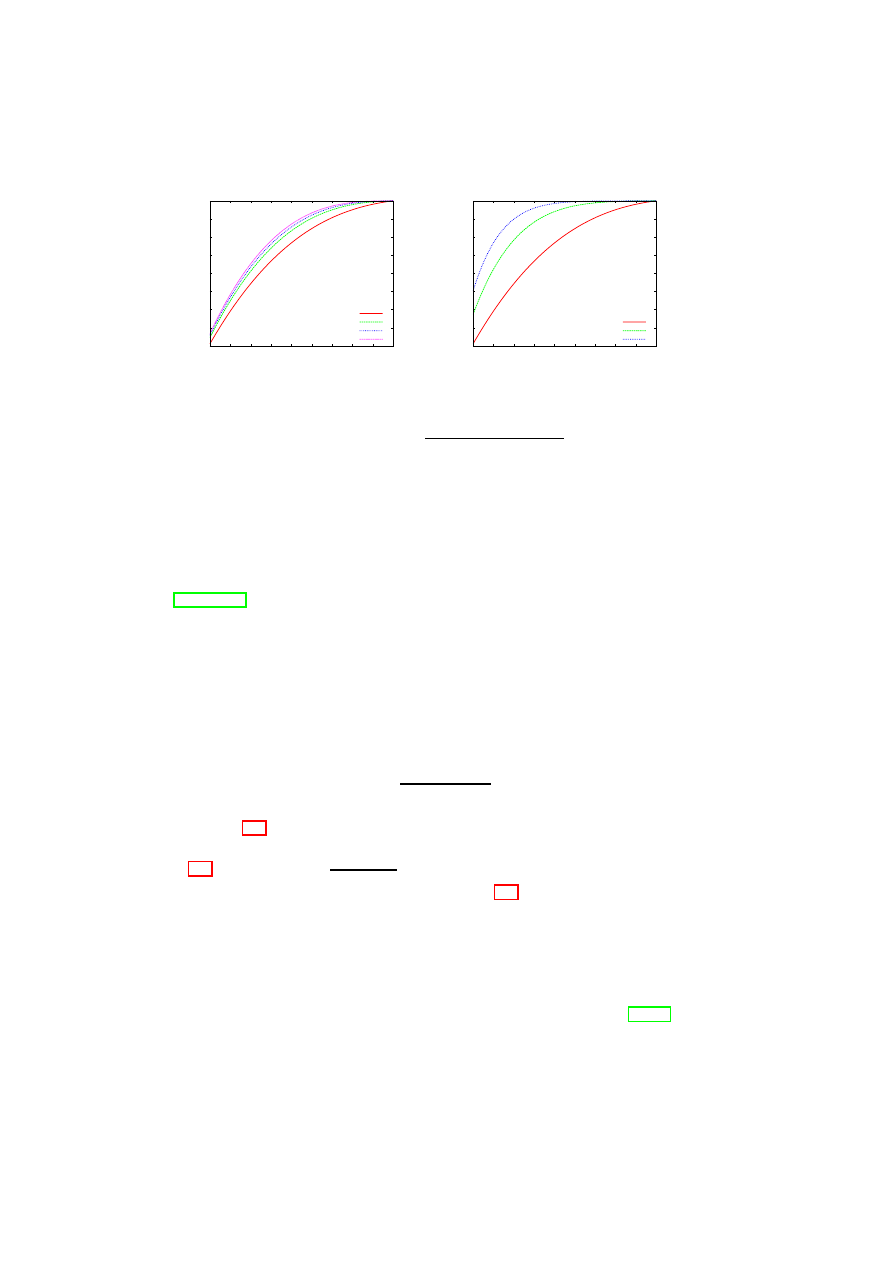
82
OpenTC D05.5 – Design and Concept of a Trusted Virtual Datacenter
0.2
0.3
0.4
0.5
0.6
0.7
0.8
0.9
1
0.1 0.2 0.3 0.4 0.5 0.6 0.7 0.8 0.9
1
Lower Bound on Reliability
of Functionality when
Moved to Hypervisor (R
F
)
Reliability of Functionality Implemented in VM (R
f
)
R
M’
= 0.75, n = 3
R
M’
= 0.90, n = 3
R
M’
= 0.95, n = 3
R
M’
= 0.99, n = 3
(a) Fixed
n
, varying
R
M
′
0.2
0.3
0.4
0.5
0.6
0.7
0.8
0.9
1
0.1 0.2 0.3 0.4 0.5 0.6 0.7 0.8 0.9
1
Lower Bound on Reliability
of Functionality when
Moved to Hypervisor (R
F
)
Reliability of Functionality Implemented in VM (R
f
)
R
M’
= 0.75, n = 3
R
M’
= 0.75, n = 6
R
M’
= 0.75, n = 9
(b) Fixed
R
M
′
, varying
n
Figure 5.8: Plot of
R
F
≥
[1
−
(1
−
R
f
R
M
′
)
n
]
[1
−
(1
−
R
M
′
)
n
]
same request. The VMM receives the results from the VM replicas. Once the
VMM has obtained replies from two replicas with identical result values for a
given client request, it forwards the result value to the corresponding client. Such a
scheme can tolerate the arbitrary failure of one VM replica, and is similar to the one
suggested in the RESH architecture for fault-tolerant replication using virtualiza-
tion [RHKSP06]. Assuming that the VMs fail independently, the system reliability
is given by
R
2
−
of
−
3
sys
=
R
H
R
V
[
R
3
M
+
3
2
R
2
M
(1
−
R
M
)]
.
Then,
R
2
−
of
−
3
sys
> R
N V
sys
gives the condition for the 2-out-of-3 replication scheme
to be more reliable than the non-virtualized service. Thus, we obtain
R
H
R
V
[
R
3
M
+
3
2
R
2
M
(1
−
R
M
)]
> R
H
R
M
=
⇒
R
V
>
1
3
R
M
−
2
R
2
M
.
(5.4)
Inequality (5.4) gives a lower bound on the hypervisor reliability for the 2-
out-of-3 replication scheme to have better reliability than the non-virtualized case.
Figure 5.9 shows a plot of
1
3
R
M
−
2
R
2
M
< R
V
<
1
. It is clear from the graph
that there exists no
R
V
value that satisfies inequality (5.4) and is less than 1 when
R
M
≤
0
.
5
. In other words, if the VM reliability (i.e., the operating system and ser-
vice reliability) is poor to begin with, then the 2-out-of-3 replication scheme will
only make the node reliability worse even if the hypervisor is ultra-reliable. This
result concurs with the well-known fact that any form of redundancy with majority
voting is not helpful for improving overall system reliability when the overall sys-
tem is composed of modules with individual reliabilities of less than
0
.
5
[Joh89].
The graph also shows that the higher the hypervisor reliability, the larger the range
of VM reliability values for which the 2-out-of-3 replication scheme has better re-
liability than the non-virtualized case. For example, when
R
V
= 0
.
98
, the range
OpenTC Document D05.5/V01 – Final R7343/2008/11/11/OpenTC Public (PU)
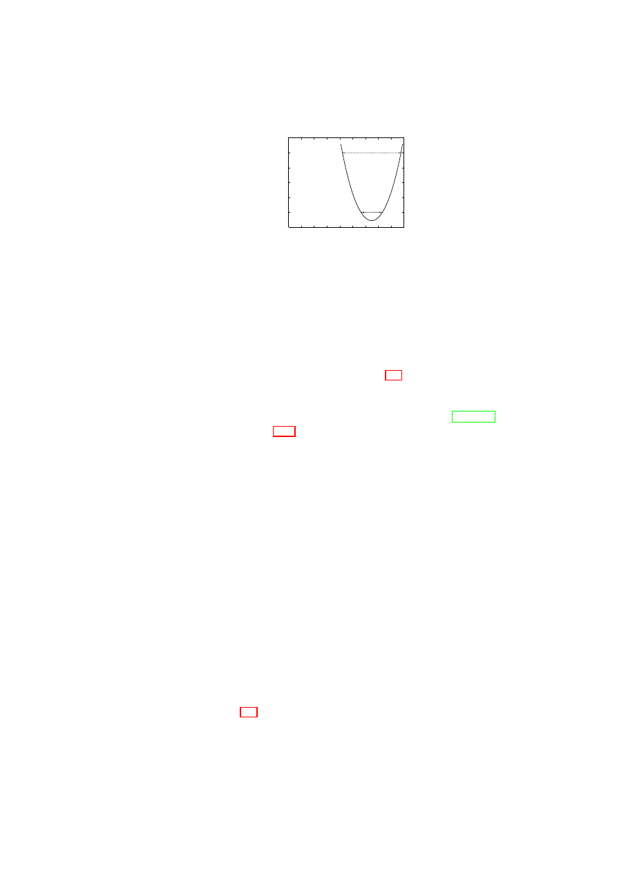
CHAPTER 5. DEPENDABLE AND SECURE VIRTUAL DATACENTERS
83
0.88
0.9
0.92
0.94
0.96
0.98
1
0.1 0.2 0.3 0.4 0.5 0.6 0.7 0.8 0.9
1
Lower Bound on Reliability
of Hypervisor (R
V
)
Reliability of Virtual Machine (R
M
)
Figure 5.9: Plot of
(3
R
M
−
2
R
2
M
)
−
1
< R
V
<
1
of VM reliability values that can be accommodated is greater than the range when
R
V
= 0
.
9
.
5.6
An Architecture for a More Reliable Xen VMM
As shown by the model-based analysis in Section 5.5, it is highly desirable to
make the VMM as reliable as possible to improve the overall reliability of a virtu-
alized node. In this section, we leverage our X-Spy implementation to propose a
reliability-enhanced design of the popular Xen open-source VMM [BDF
+
03].
The Xen VMM (Figure 5.10(a)) consists of a hypervisor core and a privileged
domain (or VM) called Dom0 or domain zero. The hypervisor core is small in size
and concerned with virtualizing the memory and CPU. Dom0 is a full-fledged VM
running a guest OS (Linux) and virtualizes other hardware devices (such as disks
and network interfaces). Dom0 is the first domain that is created, and controls
all other domains, called user domains or DomUs. For any given physical device
in Xen, the native device driver is part of at most one VM. If the device is to
be shared with other VMs, then the VM with the native device driver makes the
device available through a back-end driver. Any VM that wants to share the device
exports a virtual device driver called the front-end driver to the back-end driver.
Every front-end virtual device has to be connected to a corresponding back-end
virtual device; only then does the front-end device become active. The mapping is
one-to-one, i.e., each front-end virtual device from each user domain is mapped to a
corresponding back-end virtual device. The communication between the back-end
and front-end drivers takes places through shared memory and event channels. The
event channel is used for sending simple lightweight notifications and the shared
memory is used for sending requests and data.
As Dom0 is relatively large, we expect its reliability to be lower than that of the
hypervisor core. Thus, improving the reliability of Dom0 is crucial to improving
the reliability of the Xen VMM as a whole. We combine some of the technologies
described in Section 5.3, namely, intrusion detection, enforcing fail-stop behavior,
and intrusion response in form of software rejuvenation, to architect a more reliable
Xen VMM, which we call R-Xen.
OpenTC Document D05.5/V01 – Final R7343/2008/11/11/OpenTC Public (PU)
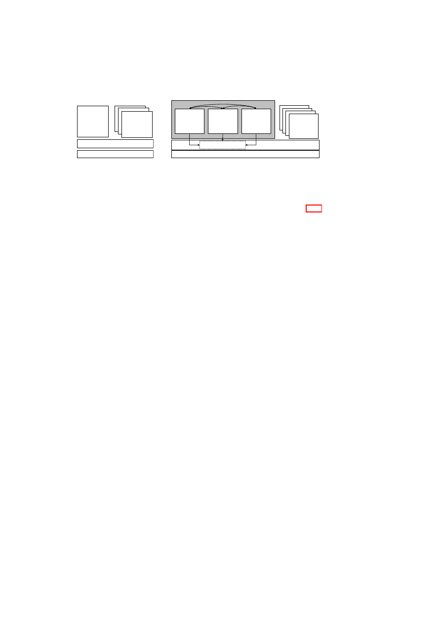
84
OpenTC D05.5 – Design and Concept of a Trusted Virtual Datacenter
Physical Hardware
Management
of VMs,
Virt. Devices,
and security
Dom0
Xen Hypervisor
User domains
(a) Normal Xen Architecture
Physical Hardware
R-Dom0
User domains
Xen Core
Dom0.A
Dom0.B
Dom0.C
mutual intrusion
monitoring
periodic intrusion reports
Leader Selection, Trust Vote,
Termination, and Rejuvenation
(b) R-Xen Architecture
Figure 5.10: Enhancing the Reliability of the Xen VMM
In R-Xen, we enhance the reliability of Dom0 by replication (Figure 5.10(b)).
Dom0 is a single logical entity that actually consists of three privileged domains,
Dom0.A, Dom0.B, and Dom0.C, with identical privilege levels. The three replicas
mutually monitor each other using the techniques we described above in our X-Spy
implementation. Specifically, each Dom0 replica is simultaneously the PVM and
the SSVM for the other two Dom0s. Periodically, the Dom0 replicas submit a fault
detection vote to the hypervisor core that indicates whether one of its two peers is
thought to be compromised. If any given Dom0 replica is labeled as being faulty
by its two peer SSVMs, then the replica will be terminated and rejuvenated by the
hypervisor. In this way, we enforce fail-stop behavior of the replica despite the
presence of a more severe kind of fault in the replica. The hypervisor core then
starts a new Dom0 replica as a replacement of the terminated one.
One of the Dom0 replicas is designated as active by the hypervisor core, and it
is this active replica that provides the back-end drivers for the devices of the user
domains. The other two replicas are designated as passive, and do not provide any
back-end devices. As mentioned above, each of the three Dom0 replicas monitors
and is being monitored by the other two. If the hypervisor gets reports from two
independent replicas labeling the third replica as faulty, then the hypervisor termi-
nates that replica and replaces it with a new Dom0 replica. If the terminated replica
is a primary, then the hypervisor designates one of the backups as the new primary
replica by re-connecting the front-end devices of the user domain(s) to the replica’s
back-end devices. The disconnection and reconnection of the user domain(s) to a
different Dom0 has already been implemented in Xen and is used for live migra-
tion of domains. Therefore, the code can be reused. The hypervisor itself has to
actively give permissions for doing the reconnection and re-routing the data from
the old Dom0 to the new one. It also has to shutdown the old Dom0 after the recon-
nection process has been completed. Using a previously started backup as the new
primary results in less interruption to the user domain than using the replacement
replica (which has to be booted from scratch) as the new primary. It also enables
the booting of the replacement replica to occur concurrently to the re-connection
of the front-end devices. Like other fault-detection-based techniques, there is the
drawback of detection latency, i.e., a time delay between the actual occurrence
of the fault and its detection. I/O requests sent by the user domain(s) during this
OpenTC Document D05.5/V01 – Final R7343/2008/11/11/OpenTC Public (PU)

CHAPTER 5. DEPENDABLE AND SECURE VIRTUAL DATACENTERS
85
latency period may have to be re-issued. On the positive side, our technique can
be implemented in a manner that is completely transparent to the user domain(s).
In other words, a DomU running on normal Xen should be able to run without
modification on this type of R-Xen as well.
OpenTC Document D05.5/V01 – Final R7343/2008/11/11/OpenTC Public (PU)

Part III
Conclusion
86

87
In this report, we have described the OpenTC approach towards a Trusted Vir-
tual Datacenter. The core idea is to build a datacenter that allows for and isolates
multiple customers while satisfying the security requirements of each customer.
Securing the access to data on persistent media and during transfer over the
network is a serious problem in distributed virtual data-center and cloud computing
scenarios. We described a framework based on TVDs and Trusted Computing for
secure network and storage virtualization that includes mechanisms for verifying
the integrity of the hypervisor, VMs, and security policy enforcement points.
This is achieved by means of so-called Trusted Virtual Domains that provide a
virtual environment for each customer. Each trusted virtual domain exposes a stan-
dardized management interface that allows customers to run existing management
software to manage their respective domains. The concept of TVDs is rigid enough
to allow consistent policy enforcement across a group of domain elements, while
being flexible enough to support policy-controlled interactions between different
TVDs. TVD policies and configurations are ‘backward-compatible’ in support-
ing options that could be taken for granted in non-virtualized data centers. For
example, co-hosting of specific customer services with those of other data-center
customers on the same physical platform could be inhibited if so desired. By incor-
porating hardware-based Trusted Computing technology, our framework allows the
creation of policy domains with attestable trust properties for each of the domain
nodes.
In order to enforce the given security requirements, we deploy the security ser-
vices described in Deliverable D05.4 [Ope08b] that allow verifiable security within
each domain. This includes validation of the trusted computing base as well as ver-
ifiable enforcement of given per-domain policies. The inclusion of integrity mea-
surement and management mechanisms as part of the physical platform’s TCBs
provides both data-center customers and administrators with a much needed view
of the elements (hypervisors, VMs, etc.) that are part of their virtual infrastructure
as well as information on the configurations of those elements. Our framework can
be used to obtain information about the elements on a ‘need-to-know’ basis with-
out having to introduce all-powerful roles of administrators with access to every
aspect of a platform.
Another insight was that building a security API that is at the same time flexi-
ble, usable, and manageable has proved to be more difficult than expected. A key
reason for this difficulty is the requirement that the API should be easily adaptable
to other hypervisor architectures and to workstation scenarios with GUI interfaces.
While addressing each of these requirements separately is feasible, their combina-
tion comes with many trade-offs.
Yet another type of trade-off concerns our aim of decomposing the Xen archi-
tecture into multiple, dedicated security services while reducing the reliance on the
management domain. While such decomposition is advantageous from a security
perspective, it tends to reduce flexibility. The availability of a full-fledged Linux
management domain with access to all systems enables easy extensibility and rapid
prototyping (scripting, adding devices, firewalls, VPNs etc), and also corresponds
OpenTC Document D05.5/V01 – Final R7343/2008/11/11/OpenTC Public (PU)

88
OpenTC D05.5 – Design and Concept of a Trusted Virtual Datacenter
to the expectations of many Xen users. In general, however, considerations of us-
ability tend to favor design decisions that are sub-optimal from a strict security
perspective.
OpenTC Document D05.5/V01 – Final R7343/2008/11/11/OpenTC Public (PU)

Bibliography
[AF02]
A. Agbaria and R. Friedman, Virtual Machine Based Hetero-
geneous Checkpointing, Software: Practice and Experience 32
(2002), no. 1, 1–19.
[BCG
+
06]
Stefan Berger, Ramon Cáceres, Kenneth Goldman, Ron Perez,
Rainer Sailer, and Leender van Doorn, vTPM: Virtualizing the
Trusted Platform Module, Proc. 15th USENIX Security Sympo-
sium, August 2006, pp. 21–21.
[BDF
+
03]
P. T. Barham, B. Dragovic, K. Fraser, S. Hand, T. L. Harris, A. Ho,
R. Neugebauer, I. Pratt, and A. Warfield, Xen and the Art of Virtu-
alization, Proc. 19th ACM Symposium on Operating Systems Prin-
ciples (SOSP-2003), October 2003, pp. 164–177.
[BGJ
+
05]
A. Bussani, J. L. Griffin, B. Jansen, K. Julisch, G. Karjoth,
H. Maruyama, M. Nakamura, R. Perez, M. Schunter, A. Tanner,
L. van Doorn, E. V. Herreweghen, M. Waidner, and S. Yoshihama,
Trusted Virtual Domains: Secure foundation for business and IT
services, Research Report RC 23792, IBM Research, November
2005.
[BS96]
T. C. Bressoud and F. B. Schneider, Hypervisor-Based Fault Toler-
ance, ACM Trans. Comput. Syst. 14 (1996), no. 1, 80–107.
[BVV05]
Doug Beck, Binh Vo, and Chad Verbowski, Detecting Stealth Soft-
ware with Strider GhostBuster, DSN ’05: Proceedings of the 2005
International Conference on Dependable Systems and Networks
(DSN’05) (Washington, DC, USA), IEEE Computer Society, 2005,
pp. 368–377.
[CBL07]
A. Cappadonia C. Basile and A. Lioy, Algebraic models to de-
tect and solve policy conflicts, MMM-ACNS 2007 (I. Kotenko
V. Gorodetsky and V.A. Skormin, eds.), CCIS, vol. 1, Springer-
Verlag, 2007, pp. 242–247.
89

90
OpenTC D05.5 – Design and Concept of a Trusted Virtual Datacenter
[CDRS07]
Serdar Cabuk, Chris Dalton, HariGovind V. Ramasamy, and
Matthias Schunter, Towards automated provisioning of secure vir-
tualized networks, Proc. 14th ACM Conference on Computer and
Communications Security (CCS-2007), October 2007, pp. 235–
245.
[CFH
+
05]
C. Clark, K. Fraser, S. Hand, J. G. Hansen, E. Jul, C. Limpach,
I. Pratt, and A. Warfield, Live Migration of Virtual Machines, Proc.
2nd Symposium on Networked Systems Design and Implementa-
tion (NSDI-2005), May 2005, pp. 273–286.
[CN01]
P. M. Chen and B. D. Noble, When Virtual is Better than Real, Pro-
ceedings of HotOS-VIII: 8th Workshop on Hot Topics in Operating
Systems, May 2001, pp. 133–138.
[Com98]
Common Criteria Project Sponsoring Organisations, Common Cri-
teria for Information Technology Security Evaluation (version 2.0),
dopted by ISO/IEC as Draft International Standard DIS 15408 1-3,
May 1998.
[DH05]
J. R. Douceur and J. Howell, Replicated Virtual Machines, Tech.
Report MSR TR-2005-119, Microsoft Research, September 2005.
[Dik00]
Jeff Dike, A User-Mode Port of the Linux Kernel, ALS’00: Pro-
ceedings of the 4th conference on 4th Annual Linux Showcase &
Conference, Atlanta (Berkeley, CA, USA), USENIX Association,
2000, pp. 7–7.
[DKC
+
02]
G. W. Dunlap, S. T. King, S. Cinar, M. A. Basrai, and P. M. Chen,
ReVirt: Enabling Intrusion Analysis through Virtual-Machine Log-
ging and Replay, SIGOPS Operating System Review 36 (2002),
no. SI, 211–224.
[EASH05]
H. Hamed E. Al-Shaer, R. Boutaba and M. Hasan, Conflict classifi-
cation and analysis of distributed firewall policies, IEEE Journal on
Selected Areas in Communications, IEEE 23 (Oct. 2005), no. 10,
2069–2084.
[FWH
+
01]
Zhi Fu, Shyhtsun Felix Wu, He Huang, Kung Loh, Fengmin Gong,
Ilia Baldine, and Chong Xu, IPSec/VPN security policy: Correct-
ness, conflict detection, and resolution, POLICY, 2001, pp. 39–56.
[GR03]
Tal Garfinkel and Mendel Rosenblum, A Virtual Machine Intro-
spection Based Architecture for Intrusion Detection, Proc. Network
and Distributed Systems Security Symposium, February 2003.
OpenTC Document D05.5/V01 – Final R7343/2008/11/11/OpenTC Public (PU)

BIBLIOGRAPHY
91
[GR05]
T. Garfinkel and M. Rosenblum, When Virtual is Harder than Real:
Security Challenges in Virtual Machine Based Computing Environ-
ments, Proc. 10th Workshop on Hot Topics in Operating Systems
(HotOS-X), May 2005.
[HDW00]
M. Dacier H. Debar and A. Wespi, A Revised Taxonomy of
Intrusion-Detection Systems, Annales des Telecommunications 55
(2000), no. (7-8), 83–100.
[IEE98]
IEEE, Standards for local and metropolitan area networks: Virtual
bridged local area networks, Tech. Report ISBN 0-7381-3662-X,
IEEE, 1998.
[IEE04]
, 802.1x: IEEE standard for local and metropolitan net-
works — port-based network access control, IEEE Standards,
2004, Revision of 802.1X-2001.
[IET02]
IETF, EtherIP: Tunneling Ethernet Frames in IP Datagrams, 2002,
RFC 3378.
[JKDC05]
A. Joshi, S .T. King, G. W. Dunlap, and P. M. Chen, Detecting
Past and Present Intrusions through Vulnerability-Specific Predi-
cates, Proc. 20th ACM Symposium on Operating Systems Princi-
ples (SOSP-2005), 2005, pp. 91–104.
[Joh89]
B. W. Johnson, Design and Analysis of Fault-Tolerant Digital Sys-
tems, Addison-Wesley, 1989.
[JRS07]
Bernhard Jansen, HariGovind Ramasamy, and Matthias Schunter,
Compliance proofs and policy enforcement for xen virtual ma-
chines, Submitted for Publication, 2007.
[JWX07]
Xuxian Jiang, Xinyuan Wang, and Dongyan Xu, Stealthy malware
detection through vmm-based "out-of-the-box" semantic view re-
construction, CCS ’07: Proceedings of the 14th ACM conference
on Computer and communications security (New York, NY, USA),
ACM, 2007, pp. 128–138.
[KC03]
S. T. King and P. M. Chen, Backtracking Intrusions, Proc. 19th
ACM Symposium on Operating Systems Principles (SOSP-2003),
2003, pp. 223–236.
[KDC05]
S. T. King, G. W. Dunlap, and P. M. Chen, Debugging Operating
Systems with Time-Traveling Virtual Machines, Proc. 2005 Annual
USENIX Technical Conference, April 2005, pp. 1–15.
[KMLC05]
S. T. King, Z. M. Mao, D. G. Lucchetti, and P. M. Chen, Enriching
Intrusion Alerts through Multi-Host Causality, Proc. Network and
Distributed System Security Symposium (NDSS-2005), 2005.
OpenTC Document D05.5/V01 – Final R7343/2008/11/11/OpenTC Public (PU)

92
OpenTC D05.5 – Design and Concept of a Trusted Virtual Datacenter
[KMP
+
04]
Evangelos Kotsovinos, Tim Moreton, Ian Pratt, Russ Ross, Kier
Fraser, Steven Hand, and Tim Harris, Global-scale Service Deploy-
ment in the XenoServer Platform, Proceedings of the 1st USENIX
Workshop on Real, Large Distributed Systems (WORLDS ’04)
(San Francisco, CA), December 2004.
[KS05]
S. Kent and K. Seo, Security Architecture for the Internet Pro-
tocol, Internet Engineering Task Force:
http://www.ietf.
org/rfc/rfc4301.txt
, December 2005, Network Working
Group RFC 4346. Obsoletes: RCF2401.
[Lit05]
L. Litty, Hypervisor-Based Intrusion Detection, Ph.D. thesis, Uni-
versity of Toronto, 2005.
[LMJ04]
Marcos Laureano, Carlos Maziero, and Edgard Jamhour, Intrusion
Detection in Virtual Machine Environments, EUROMICRO ’04:
Proceedings of the 30th EUROMICRO Conference (EUROMI-
CRO’04) (Washington, DC, USA), IEEE Computer Society, 2004,
pp. 520–525.
[LS99]
Emil Lupu and Morris Sloman, Conflicts in policy-based dis-
tributed system management, IEEE Transaction on Software En-
gineering 25 (1999), no. 6, 852–869.
[N. 01]
N. Dunlop, J. Indulska, K. A. Raymond, A formal specification
of conflicts in dynamic policy-based management systems, DSTC
Technical Report, CRC for Enterprise Distributed Systems, Uni-
versity of Queensland, Australia, August 2001.
[NLPFMA04] Jr. Nick L. Petroni, Timothy Fraser, Jesus Molina, and William A.
Arbaugh, Copilot - A Coprocessor-based Kernel Runtime In-
tegrity Monitor, SSYM’04: Proceedings of the 13th conference on
USENIX Security Symposium (Berkeley, CA, USA), USENIX As-
sociation, 2004, pp. 13–13.
[Ope08a]
Open Trusted Computing (OpenTC) Project, The OpenTC Project
Homepage, 2008,
http://www.opentc.net/
.
[Ope08b]
OpenTC Workpackage 05, Design of the cross-domain security
services, Deliverable, The OpenTC Project
www.opentc.net
,
05/26/2008.
[RHKSP06]
H. P. Reiser, F. J. Hauck, R. Kapitza, and W. Schröder-Preikschat,
Hypervisor-Based Redundant Execution on a Single Physical Host,
Proc. 6th European Dependable Computing Conference (EDCC-
2006), October 2006, p. S.2.
OpenTC Document D05.5/V01 – Final R7343/2008/11/11/OpenTC Public (PU)

BIBLIOGRAPHY
93
[RK07]
Hans P. Reiser and Rudiger Kapitza, Hypervisor-Based Efficient
Proactive Recovery, SRDS ’07: Proc. 26th IEEE International
Symposium on Reliable Distributed Systems, IEEE Computer So-
ciety, Washington, DC, USA, 2007, pp. 83–92.
[Ros08]
Russ Ross, CoWNFS, http://www.russross.com/CoWNFS.html,
2008.
[RYG00]
D. Pendarakis R. Yavatkar and R. Guerin, A framework for policy-
based admission control, RFC 2753, January 2000.
[SS05]
A-R. Sadeghi and C. Stüble, Property-based Attestation for Com-
puting Platforms: Caring about Properties, not Mechanisms, Proc.
2004 Workshop on New Security Paradigms (NSPW-2004) (New
York, NY, USA), ACM Press, 2005, pp. 67–77.
[ste01]
stealth, Adore-ng v0.42, http://packetstormsecurity.org/, 2001.
[Tru03]
Trusted Computing Group, TPM Main Specification v1.2, Novem-
ber 2003,
https://www.trustedcomputinggroup.org
.
[VMw]
VMware, VMware Double-Take,
http://www.vmware.com/
pdf/vmware_doubletake.pdf
.
[Was06]
Washington Post, A Time to Patch, 2006,
http://blog.
washingtonpost.com/securityfix/2006/01/a_
time_to_patch.html
.
[Wes01]
Andrea Westerinen, Terminology for policy-based management,
RFC 3198, November 2001.
[ZvDJ
+
02]
Xiaolan Zhang, Leendert van Doorn, Trent Jaeger, Ronald Perez,
and Reiner Sailer, Secure coprocessor-based intrusion detection,
EW10: Proceedings of the 10th workshop on ACM SIGOPS Euro-
pean workshop (New York, NY, USA), ACM, 2002, pp. 239–242.
OpenTC Document D05.5/V01 – Final R7343/2008/11/11/OpenTC Public (PU)
Document Outline
- OpenTC_D05.5_Trusted_Virtual_Datacenter_FINAL.pdf
- OpenTC_D05.5_Trusted_Virtual_Datacenter_FINAL.pdf
- otcD05.5-v01-VirtualDatacenter.pdf
- otcD05.5-v01-VirtualDatacenter.pdf