D05.6 Final Report of OpenTC Workpackage 5
(M37) November 2008
Project number
IST-027635
Project acronym
Open_TC
Project title
Open Trusted Computing
Deliverable Type
Report
Reference number
IST-027635/D05.6/V01 Final
Title
D05.6 Final Report of OpenTC Workpackage
5
WPs contributing
WP05
Due date
November 2008 (M37)
Actual submission date
January 15th, 2009
Responsible Organisation
IBM (Matthias Schunter)
Authors
CUCL, HP, IBM, IAIK, ITAS, RUB, Polito
Abstract
This report summarizes and consolidates the
main results from OpenTC Workpackage 05
“SecurityManagement and Infrastructure”.
Keywords
OpenTC, Virtualization, Trusted Computing,
Security Services, Security Management,
Virtual Systems
Dissemination level
Public
Revision
V01 Final
Instrument
IP
Start date of the
project
1
st
November 2005
Thematic Priority
IST
Duration
42 months

A
BSTRACT
This report summarizes and consolidates the main results from OpenTC Workpackage
05 “Security Management and Infrastructure”. The goal of Workpackage 5 has been to
develop mechanisms for managing security of virtual systems while leveraging trusted
computing technologies for verifiability and protection.
Part I of the deliverable introduces our goals and surveys the approach we have
taken from a high-level perspective. Part II then describes key building blocks in detail.
Part III describes the WP5 concepts in the demonstrator and concludes the deliverable
by evaluating our prototype and documenting our future outlook.
C
ONTRIBUTORS AND
A
CKNOWLEDGEMENTS
The following people were the main contributors to this report (alphabetically by or-
ganisation): Theodore Hong, Eric John, Derek Murray (CUCL); Serdar Cabuk, Chris
Dalton, Dirk Kuhlmann, David Plaquin (HP); Konrad Eriksson, Bernhard Jansen,
HariGovind V. Ramasamy, Matthias Schunter, Axel Tanner, Andreas Wespi, Diego
Zamboni (IBM); Peter Lipp, Martin Pirker (IAIK); Arnd Weber (ITAS); Frederik
Armknecht, Yacine Gasmi, Ahmad-Reza Sadeghi, Patrick Stewin, Martin Unger
(RUB); Gianluca Ramunno, Davide Vernizzi (Polito).
We would like to thank our reviewer Peter Lipp from IAIK Graz. Furthermore, we
would like to thank the other members of the OpenTC project for helpful discussions
and valuable contributions to the research that is documented in this report.
2
If you need further information, please visit our website
www.opentc.net
or contact the
coordinator:
Technikon Forschungs-und Planungsgesellschaft mbH
Burgplatz 3a, 9500 Villach, AUSTRIA
Tel.+43 4242 23355 -0
Fax. +43 4242 23355 -77
Email
coordination@opentc.net
The information in this document is provided “as is”, and no guarantee
or warranty is given that the information is fit for any particular purpose.
The user thereof uses the information at its sole risk and liability.

Final Report of OpenTC Workpackage 5
OpenTC Workpackage 5
1
OpenTC Deliverable D05.6
V01 – Final Revision. 7628 (OpenTC Public (PU))
2009/01/15

2
OpenTC D05.6 – Final Report of OpenTC Workpackage 5
OpenTC Document D05.6/V01 – Final R7628/2009/01/15/OpenTC Public (PU)

Contents
1
Introduction and Outline
7
1.1
Introduction . . . . . . . . . . . . . . . . . . . . . . . . . . . . . . .
7
1.2
Our Contribution . . . . . . . . . . . . . . . . . . . . . . . . . . . .
8
1.3
Outline of this Report . . . . . . . . . . . . . . . . . . . . . . . . . .
8
I
Overview and Related Work
11
1.4
Dependability of Virtual Systems . . . . . . . . . . . . . . . . . . . .
12
2
Security Policies for Virtual Data Centers
15
2.1
High-level Policy Model . . . . . . . . . . . . . . . . . . . . . . . .
15
2.2
Security Objectives and Policy Enforcement Points . . . . . . . . . .
16
2.3
Example Policy Refinements for Protected Resources . . . . . . . . .
18
3
Unified Policy Enforcement for Virtual Data Centers
22
3.1
TVD Infrastructure . . . . . . . . . . . . . . . . . . . . . . . . . . .
22
3.2
Virtual Networking Infrastructure
. . . . . . . . . . . . . . . . . . .
23
3.3
Virtual Storage Infrastructure . . . . . . . . . . . . . . . . . . . . . .
25
3.4
TVD Admission Control . . . . . . . . . . . . . . . . . . . . . . . .
26
4
Background and Related Work
29
4.1
Overview of Trusted Virtual Domains . . . . . . . . . . . . . . . . .
29
4.2
Trusted Computing – The TCG Approach . . . . . . . . . . . . . . .
30
4.3
Trusted Channels . . . . . . . . . . . . . . . . . . . . . . . . . . . .
31
4.4
Secure Network Virtualization . . . . . . . . . . . . . . . . . . . . .
31
II
Building Blocks of the OpenTC Security Architecture
33
5
Policy Enforcement and Compliance
34
5.1
Introduction . . . . . . . . . . . . . . . . . . . . . . . . . . . . . . .
34
5.2
Formal Integrity Model for Virtual Machines
. . . . . . . . . . . . .
35
5.3
The PEV Integrity Architecture . . . . . . . . . . . . . . . . . . . . .
38
5.4
Realization using Xen and Linux . . . . . . . . . . . . . . . . . . . .
41
5.5
Use Cases . . . . . . . . . . . . . . . . . . . . . . . . . . . . . . . .
43
5.6
Conclusion . . . . . . . . . . . . . . . . . . . . . . . . . . . . . . .
49
3
4
OpenTC D05.6 – Final Report of OpenTC Workpackage 5
6
Hierarchical Integrity Management
51
6.1
Introduction . . . . . . . . . . . . . . . . . . . . . . . . . . . . . . .
51
6.2
Design Overview . . . . . . . . . . . . . . . . . . . . . . . . . . . .
52
6.3
Basic Integrity Management . . . . . . . . . . . . . . . . . . . . . .
54
6.4
Hierarchical Integrity Management . . . . . . . . . . . . . . . . . . .
58
6.5
Policy Verification for Security Services . . . . . . . . . . . . . . . .
63
6.6
Implementation in Xen . . . . . . . . . . . . . . . . . . . . . . . . .
64
6.7
Conclusions . . . . . . . . . . . . . . . . . . . . . . . . . . . . . . .
68
7
Secure Virtualized Networking
69
7.1
Introduction . . . . . . . . . . . . . . . . . . . . . . . . . . . . . . .
69
7.2
Design Overview . . . . . . . . . . . . . . . . . . . . . . . . . . . .
70
7.3
Networking Infrastructure
. . . . . . . . . . . . . . . . . . . . . . .
74
7.4
TVD Infrastructure . . . . . . . . . . . . . . . . . . . . . . . . . . .
81
7.5
Auto-deployment of Trusted Virtual Domains . . . . . . . . . . . . .
87
7.6
Implementation in Xen . . . . . . . . . . . . . . . . . . . . . . . . .
92
7.7
Discussion . . . . . . . . . . . . . . . . . . . . . . . . . . . . . . . .
95
8
Public Key Infrastructure
96
8.1
Introduction . . . . . . . . . . . . . . . . . . . . . . . . . . . . . . .
96
8.2
Basic Trusted Computing PKI . . . . . . . . . . . . . . . . . . . . .
97
8.3
Trusted Platform Agent . . . . . . . . . . . . . . . . . . . . . . . . .
100
8.4
XKMS mapping . . . . . . . . . . . . . . . . . . . . . . . . . . . . .
102
8.5
Open Issues . . . . . . . . . . . . . . . . . . . . . . . . . . . . . . .
110
9
Trusted Channels using OpenSSL
112
9.1
Motivation . . . . . . . . . . . . . . . . . . . . . . . . . . . . . . . .
112
9.2
Requirement Analysis . . . . . . . . . . . . . . . . . . . . . . . . . .
114
9.3
Basic Definitions . . . . . . . . . . . . . . . . . . . . . . . . . . . .
115
9.4
Adapted TLS Handshake . . . . . . . . . . . . . . . . . . . . . . . .
116
9.5
Detailed Description of Attestation Data Structures . . . . . . . . . .
119
9.6
Generic System Architecture . . . . . . . . . . . . . . . . . . . . . .
122
9.7
A Trusted Channel Implementation with OpenSSL . . . . . . . . . .
124
9.8
Security Considerations . . . . . . . . . . . . . . . . . . . . . . . . .
127
9.9
Functional Considerations . . . . . . . . . . . . . . . . . . . . . . .
128
9.10 Summary . . . . . . . . . . . . . . . . . . . . . . . . . . . . . . . .
129
10 Towards Dependability and Attack Resistance
130
10.1 Introduction to Dependable Virtualization . . . . . . . . . . . . . . .
130
10.2 Using Virtualization for Dependability and Security . . . . . . . . . .
131
10.3 Xen-based Implementation of Intrusion Detection and Protection . . .
134
10.4 Quantifying the Impact of Virtualization on Node Reliability . . . . .
143
10.5 An Architecture for a More Reliable Xen VMM . . . . . . . . . . . .
147
III
Evaluation and Outlook
151
11 Security Management Demonstrator
152
11.1 Overview . . . . . . . . . . . . . . . . . . . . . . . . . . . . . . . .
152
11.2 Security Services . . . . . . . . . . . . . . . . . . . . . . . . . . . .
153
OpenTC Document D05.6/V01 – Final R7628/2009/01/15/OpenTC Public (PU)
CONTENTS
5
11.3 TVD Master, Proxies and Proxy Factories . . . . . . . . . . . . . . .
155
11.4 Secure Virtual Network subsystem . . . . . . . . . . . . . . . . . . .
155
11.5 Trusted Channel Proxies . . . . . . . . . . . . . . . . . . . . . . . .
156
12 Evaluation of the Prototype
157
12.1 Performance Evaluation . . . . . . . . . . . . . . . . . . . . . . . . .
157
12.2 Limitations of our Prototype . . . . . . . . . . . . . . . . . . . . . .
159
13 Conclusion and Outlook
161
13.1 Lessons Learned
. . . . . . . . . . . . . . . . . . . . . . . . . . . .
161
13.2 The Future of Secure Virtualization and Trusted Computing . . . . . .
162
13.3 Conclusions . . . . . . . . . . . . . . . . . . . . . . . . . . . . . . .
164
Bibliography
165
OpenTC Document D05.6/V01 – Final R7628/2009/01/15/OpenTC Public (PU)

6
OpenTC D05.6 – Final Report of OpenTC Workpackage 5
OpenTC Document D05.6/V01 – Final R7628/2009/01/15/OpenTC Public (PU)

Chapter 1
Introduction and Outline
1.1
Introduction
Hardware virtualization is enjoying a resurgence of interest fueled in part by its cost-
saving potential. By allowing multiple virtual machines to be hosted on a single phys-
ical server, virtualization helps improve server utilization, reduce management and
power costs, and control the problem of server sprawl.
A prominent example in this context is data centers. The infrastructure provider,
who owns, runs, and manages the data center, can transfer the cost savings to its cus-
tomers or outsourcing companies, whose virtual infrastructures are hosted on the data
center’s physical resources. A large number of the companies that outsource their op-
erations are small and medium businesses or SMBs, which cannot afford the costs of a
dedicated data center in which all the data center’s resources are used to host a single
company’s IT infrastructure. Hence, the IT infrastructure belonging to multiple SMBs
may be hosted inside the same data center facility. Today, even in such “shared” data
centers, each run on distinct physical resources and there is no resource sharing among
various customers. In this so-called physical cages model, the customers are physically
isolated from each other in the same data center.
Limited trust in the security of virtual datacenters is one major reason for customers
not sharing physical resources. Since management is usually performed manually, ad-
ministrative errors are commonplace. While this may lead to down times in virtual
datacenters used by a single customer, it can lead to information leakages to competi-
tors if the datacenter is shared. Furthermore, multiple organizations will only allow
sharing of physical resources if they can trust that security incidents cannot spread
across the isolation boundary separating two customers.
Security Objectives
Our main security objective is to provide isolation among dif-
ferent domains that is comparable
1
with the isolation obtained by providing one infras-
tructure for each customer. In particular, we require a security architecture that protects
those system components that provide the required isolation or allow to verifiably rea-
son about their trustworthiness of and also of any peer endpoint (local or remote) with
a domain, i.e., whether they conforms to the underlying security policy.
We achieve this by grouping VMs dispersed across multiple physical resources
into a virtual zone in which customer-specified security requirements are automatically
1
Note that unlike physical isolation, we do not solve the problem of covert channels.
7
8
OpenTC D05.6 – Final Report of OpenTC Workpackage 5
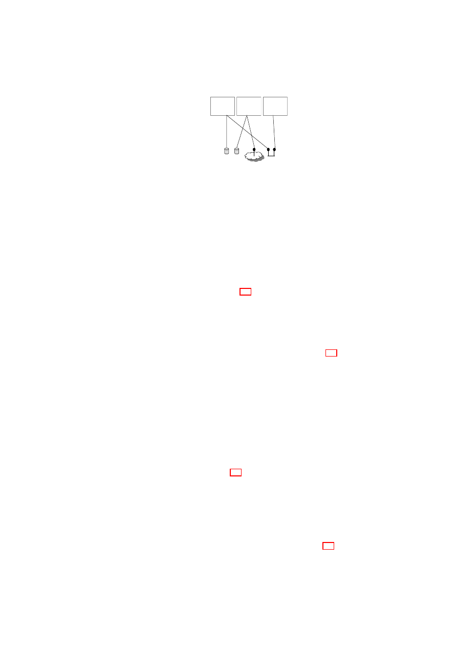
Hardware Platform
Hypervisor
Security Services
VM
A1
VM
A2
VM
A3
VM
A4
TVD1
Master
TVD1
Master
TVD1
Master
Proxy1
…
Proxy2
Hardware Platform
Hypervisor
Security Services
VM
B1
VM
B2
VM
B3
VM
B4
Proxy1
…
Proxy2
H
o
s
t
B
H
o
s
t
A
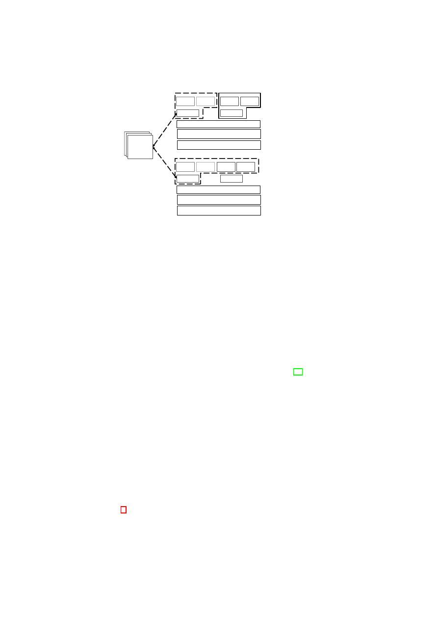
Figure 1.1: TVD Architecture: High-Level Overview.
enforced. Even if VMs are migrated (say, for load-balancing purposes) the logical
topology reflected by the virtual domain should remain unchanged. We deploy Trusted
Computing (TC) functionalities to determine the trustworthiness (assure the integrity)
of the policy enforcement components.
Such a model would provide better flexibility, adaptability, cost savings than to-
day’s physical cages model while still providing the main security guarantees required
for applications such as datacenters.
1.2
Our Contribution
In this deliverable, we provide a blueprint for realizing integrity and isolation in virtual
systems. We do this by supporting a logical cages model, in particular for virtualized
data centers, based on a concept called Trusted Virtual Domains or TVDs [16]. Based
on previous work, we describe a security management framework that helps to realize
the abstraction of TVDs by guaranteeing reliable isolation and flow control between
domain boundaries. Our framework employs networking and storage virtualization
technologies as well as Trusted Computing for policy verification. Our main contribu-
tions are (1) combining these technologies to realize TVDs and (2) orchestrating them
through a management framework that automatically enforces isolation among differ-
ent zones. In particular, our solution aims at automating the verification, instantiation
and deployment of the appropriate security mechanisms and virtualization technolo-
gies based on an input security model, which specifies the required level of isolation
and permitted information flows.
1.3
Outline of this Report
This report is structured in three parts. Part I surveys our work and summarizes related
work in Chapter 4. Part II describes selected building blocks of our security architecture
in detail. Part III describes WP5 components of our prototype and finally reflects on
OpenTC Document D05.6/V01 – Final R7628/2009/01/15/OpenTC Public (PU)

CHAPTER 1. INTRODUCTION AND OUTLINE
9
our lessons learned and documents our outlook onto the future of trusted computing
and virtualization.
The first technical component in Part II is the integrity and assurance management
of the OpenTC Security Services. This has two aspects: In Section 5 we describe how
integrity statements about virtual machines can be made and how data can be bound
to the integrity of a machine. We also describe how to protect the privacy of users
using our system. In Section 6 we extend these results to cover hierarchical integrity
management, i.e., the integrity protection of packages of multiple virtual machines and
the related components.
The second component is our network security architecture described in Chapter 7.
It implements two key ideas. The first idea is to provide secure virtual networks (so-
called trusted virtual domains) that transparently connect VMs on multiple hosts. The
second idea is to automatically provision the required protection mechanisms such that
the networks guarantee a given set of user requirements.
The third component described in Chapter 8 is the public key infrastructure (PKI)
that manages the keys used four security mechanisms. It also includes trusted comput-
ing extensions to existing PKI standards.
The fourth component are trusted channels in Chapter 9 that enable to establish a
secure channel while verifying the integrity of the peer. This allows users to not only
guarantee the integrity of a given machine but also to securely connect to the machine
that has been validated.
The fifth and final concept is our approach to attack and failure resilience as doc-
ument in Chapter 10. This concept comprises three main ideas. The first is to use
introspection to detect viruses and other failures inside a running VM. The second is
to implement redundancy for VMs and key hypervisor components such as network or
disk drivers. The final idea combining them is to monitor VMs and rejuvenate VMs
that are failed or are at risk of failing. Overall, this allows a substantial increase in the
resiliency of the services running on this platform.
OpenTC Document D05.6/V01 – Final R7628/2009/01/15/OpenTC Public (PU)

10
OpenTC D05.6 – Final Report of OpenTC Workpackage 5
OpenTC Document D05.6/V01 – Final R7628/2009/01/15/OpenTC Public (PU)

Part I
Overview and Related Work
11

12
OpenTC D05.6 – Final Report of OpenTC Workpackage 5
1.4
Dependability of Virtual Systems
We now provide a sampling of related work in the area of using VMs for improving de-
pendability. We also compare our X-Spy intrusion detection framework with previous
hypervisor-based intrusion detection systems. Many of these works, including ours,
implicitly trust the virtualization layer to function properly, to isolate the VMs from
each other, and to control the privileged access of certain VMs to other VMs. Such a
trust can be justified by the observation that a typical hypervisor consists of some tens
of thousands lines-of-code (LOC), whereas a typical operating system today is on the
order of millions LOC [40]. This allows a much higher assurance for the code of a
hypervisor.
Bressoud and Schneider [15] implemented a primary-backup replication protocol
tolerant to benign faults at the VMM level. The protocol resolves non-determinism
by logging the results of all non-deterministic actions taken by the primary and then
applying the same results at the backups to maintain state consistency.
Double-Take [124] uses hardware-based real-time synchronous replication to repli-
cate application data from multiple VMs to a single physical machine so that the appli-
cation can automatically fail over to a spare machine by importing the replicated data in
case of an outage. As the replication is done at the file system level below the VM, the
technique is guest-OS-agnostic. Such a design could provide the basis for a business
model in which multiple client companies outsource their disaster recovery capability
to a disaster recovery hot-site that houses multiple physical backup machines, one for
each client.
Douceur and Howell [29] describe how VMMs can be used to ensure that VMs
satisfy determinism and thereby enable state machine replication at the VM level rather
than the application level. Specifically, they describe how a VM’s virtual disk and clock
can be made deterministic with respect to the VM’s execution. The design relieves the
application programmer of the burden of structuring the application as a deterministic
state machine. Their work is similar to Bressoud and Schneider’s approach [15] of
using a VMM to resolve non-determinism. However, the difference lies in the fact
that whereas Bressoud and Schneider’s approach resolves non-determinism using the
results of the primary machine’s computation, Douceur and Howell’s design resolves
non-determinism a priori by constraining the behavior of the computation.
Dunlap et al. describe ReVirt [31] for VM logging and replay. ReVirt encapsulates
the OS as a VM, logs non-deterministic events that affect the VM’s execution, and
uses the logged data to replay the VM’s execution later. Such a capability is useful
to recreate the effects of non-deterministic attacks, as they show later in [59]. Their
replay technique is to start from a checkpoint state and then roll forward using the log
to reach the desired state.
Joshi et al. [59] combine VM introspection with VM replay to analyze whether a
vulnerability was activated in a VM before a patch was applied. The analysis is based
on vulnerability-specific predicates provided by the patch writer. After the patch has
been applied, the same predicates can be used during the VM’s normal execution to
detect and respond to attacks.
Backtracker [64] can be used to identify which application running inside a VM was
exploited on a given host. Backtracker consists of an online component that records OS
objects (such as processes and files) and events (such as read, write, and fork), and an
offline component that generates graphs depicting the possible chain of events between
the point at which the exploit occurred and the point at which the exploit was detected.
An extension of Backtracker [66] has been used to track attacks from a single host
OpenTC Document D05.6/V01 – Final R7628/2009/01/15/OpenTC Public (PU)

13
at which an infection has been detected to the originator of the attack and to other hosts
that were compromised from that host. The extension is based on identifying causal
relationships, and has also been used for correlating alerts from multiple intrusion de-
tection systems.
King et al. [65] describe the concept of time-traveling virtual machines (TTVMs),
in which VM replay is used for low-overhead reverse debugging of operating systems
and for providing debugging operations such as reverse break point, reverse watch
point, and reverse single step. Combining efficient checkpointing techniques with Re-
Virt, TTVMs can be used by programmers to go to a particular point in the execution
history of a given run of the OS. To recreate all relevant state for that point, TTVMs
log all sources of non-determinism.
Garfinkel and Rosenblum [40] introduced the idea of hypervisor-based intrusion
detection, and pointed out the advantages of this approach and its applicability not
only for detection, but also for protection. Their Livewire system uses a modified
VMware workstation as hypervisor and implements various polling-based and event-
driven sensors. Compared with Livewire, our X-Spy system employs more extensive
detection techniques (e.g., by checking not only processes, but also kernel modules
and file systems) and protection techniques (such as pre-checking and white-listing of
binaries, and kernel sealing) with an explicit focus on rootkit detection. In addition,
X-Spy enables easy forensic analysis.
Zhang et al. [132] and Petroni et al. [85] use a secure coprocessor as the basis for
checking the integrity of the OS kernel running on the main processor. However, as the
coprocessor can only read the memory of the machine monitored, only polling-based
intrusion detection is possible. In contrast, X-Spy can perform both polling-based
and event-driven intrusion detection. Specifically, it can intercept and deny certain
requested actions (such as suspicious system calls), and therefore has the capability to
not only detect but also protect.
Laureano et al. [71] employ behavior-based detection of anomalous system call se-
quences after a learning phase in which “normal” system calls are identified. Processes
with anomalous system call sequences are labeled suspicious. For these processes, cer-
tain dangerous system calls will in turn be blocked. The authors describe a prototype
based on a type-II hypervisor, namely, User-Mode Linux (UML) [28].
The ISIS system of Litty [75] is also based on UML. ISIS runs as a process in the
host operating system and detects intrusions in the guest operating system by using
the
ptrace
system call for instrumenting the guest UML kernel. Unlike X-Spy, ISIS
focuses mostly on intrusion detection and not protection.
Jiang et al. [57] describe the VMwatcher system, in which host-based anti-malware
software is used to monitor a VM from within a different VM. X-Spy and VMwatcher
are similar in that both use the hypervisor as a bridge for cross-VM inspection, and both
tackle the semantic gap problem. While their work focuses on bridging the semantic
gap on a multitude of platforms (hypervisors and operating systems), our work focuses
on employing more extensive detection mechanisms (such as checking not only pro-
cesses, but also kernel modules, network connections, and file systems) on a single
hypervisor. In contrast to X-Spy, VMwatcher does not include event-driven detection
methods or protection techniques.
The Strider GhostBuster system by Beck et al. [12] is similar to X-Spy in that both
use a differential view of system resources. Strider GhostBuster compares high-level
information (such as information obtained by an OS command) with low-level infor-
mation (e.g., kernel information) to detect malicious software trying to hide system
resources from the user and administrator. However, such a comparison has limited
OpenTC Document D05.6/V01 – Final R7628/2009/01/15/OpenTC Public (PU)

14
OpenTC D05.6 – Final Report of OpenTC Workpackage 5
effectiveness as detection takes place in the same (potentially compromised) OS envi-
ronment. Beck et al. also compare the file system view obtained from a potentially
compromised OS with the view obtained from an OS booted from a clean media. The
disadvantage of such an approach is that it requires multiple reboots and is limited to
checking only persistent data (such as file system) and not run-time data.
OpenTC Document D05.6/V01 – Final R7628/2009/01/15/OpenTC Public (PU)

Chapter 2
Security Policies for Virtual
Data Centers
Data centers provide computing and storage services to multiple customers. Customers
are ideally given dedicated resources such as storage and physical machines. In the
physical cages approach, only few resources such as the Internet connection may be
shared between multiple customers. For cost efficiency, our logical cages approach
promotes securely extending sharing to other resources such as storage and networks.
This is enabled by preventing unauthorized information exchange via shared resources.
To model and implement the logical caging approach, we introduce a domain-based
security model for enforcing unified security policies in virtualized data centers. We
focus on isolation policies that mimic physical separation of data center customers. Our
goal is to logically separate networks, storage, VMs, users, and other virtual devices of
one customer from another customer. For our purposes, we define domain isolation as
the ability to enforce security policies within a domain independently of other domains
that may co-exist on the same infrastructure and interact with that domain. The core
idea is to use this isolation property as a foundation for guaranteeing desired security
properties within each virtual domain while managing shared services under mutually
agreed policies.
We now explain the policies that describe this controlled information exchange in a
virtualized data center. In Section 3 we describe the individual components that enable
us to enforce these policies.
2.1
High-level Policy Model
The security model includes two high-level policies defining the security objectives
that must be provided by the underlying infrastructure:
Inter-TVD Policy: By default, each TVD is isolated from the outside world. The
high-level information-exchange policy defines whether and how information
can be exchanged with other TVDs. If no information flow with other TVDs is
permitted, no resources can be shared unless the data center operator can guar-
antee that the isolation is preserved. If information flow to/from other TVDs is
allowed, sub-policies further qualify the exact information flow policy for the
individual resources.
15
16
OpenTC D05.6 – Final Report of OpenTC Workpackage 5
VPE
1
(Role
1)
Roles of Single-Domain
Machines (subjects):
Multi-Domain Resources
(objects)
Operations[parameter]
(mode):
VPE
2
(Role
2)
VPE
3
(Role
3)
Figure 2.1: Policy Model: Single-TVD Machines operate on Shared Resources
Intra-TVD Policy: Domain policies allow TVD owners (e.g., customers) to define the
security objectives within their own TVDs. Examples of such policies include
how the internal communication is to be protected and under what conditions
resources (e.g., storage, machines) can join a particular TVD.
We further define more fine-grained policies by the use of roles that can be assigned
to any member VM, say to a member machine. This allows us to define and enforce
role-based policies within and across TVDs. For example, machines can now assume
internal or gateway roles with corresponding permissions; while a workstation may not
be allowed to connect to non-TVD networks, machines with the “firewall” role can be
allowed to connect to selected other networks. Figure 2.1 depicts three VMs in a single
TVD. Each VM is given different levels of access to resources with respect to their role
for that TVD.
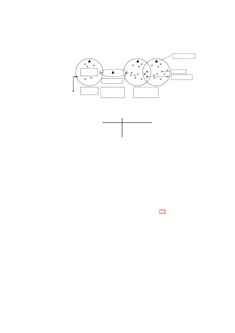
2.2
Security Objectives and Policy Enforcement Points
Policies are enforced for all shared resources in the TVD infrastructure (see Figure 2.2).
The basis of all policies is isolation at the boundary of each TVD. By default, each
resource is associated with a single domain. This achieves a basic level of isolation. If
information flow between TVDs is allowed, resources can also be member of different
TVDs. For example, a TVD can allow certain types of resources on certain hosts to
provide services also to other domains. Each TVD defines rules regarding in-bound
and out-bound information flow for restricting communication with the outside world.
The underlying policy-enforcement infrastructure then has to ensure that only resources
trusted by all TVDs are shared.
Architecturally, there are two ways of enforcing such rules, depending on the trust
between the TVDs. The first method involves two shared resources connected by an
intermediate domain. In this method, each TVD enforces its side of the flow control
by means of its own shared resource. An example of this type of connection is the one
that exists between TVD A and TVD B in Figure 2.2. This method is used when the
trust level between TVD A and TVD B is low, and the two cannot agree on a shared
resource that is mutually trusted. The shared resource in TVD A will enforce TVD A’s
policies regarding in-bound traffic from TVD B, even if the shared resource in TVD B
does not enforce TVD B’s policies regarding out-bound traffic. The shared resources
can be thought of being a part of a “neutral” TVD (TVD AB) with its own set of mem-
bership requirements. The second method that requires shared trust is to establish one
or more shared resources that are accessed from both TVDs while allowing controlled
information flow. This mechanism is used between TVD B and TVD C in Figure 2.2.
OpenTC Document D05.6/V01 – Final R7628/2009/01/15/OpenTC Public (PU)
CHAPTER 2. SECURITY POLICIES FOR VIRTUAL DATA CENTERS
17
TVD A
TVD B
Internet
Membership
Constraints
Flow Enforcement
by Single-trust
Shared Resources
Isolation
Enforcement
TVD C
Flow Enforcement
by Mutually Trusted
Shared Resources
TVD AB
Shared Resource
Internal
Trusted/Shared
Resource Types:
Machine in Role
Figure 2.2: Usage Control for Shared Resources: Machines use resources belonging to
TVDs.
From / to
D
I
D
D
D
i
D
I
1
1
0
D
D
0
1
1
D
i
0
1
1
Table 2.1: High-level Directed Flow Control Matrix for Internet
D
I
, DMZ
D
D
, and
Intranet
D
i
.
Security within a virtual domain is finally obtained by defining and enforcing mem-
bership requirements that resources have to satisfy prior to being admitted to the TVD
and for retaining the membership. This may also include special requirements for
different machine types: Because, for example, shared resources play a key role in
restricting information flow between TVDs, the software on those machines may be
subject to additional integrity verification as compared to the software on regular VMs.
2.2.1
Permitted Flows in Data Centers
At a high level flow control policies define the allowed traffic flow between two do-
mains and how the domains should be protected. Allowed information flows can be
represented by a simple flow control matrix as depicted in Table 2.1, where
1
allows in-
formation flow and
0
denies it. This example implements a basic enterprise policy that
regulates incoming flow from untrusted outside entities (
D
I
) through a semi-trusted
intermediary domain (
D
D
), and disallows any outgoing flow. Note that this matrix is
directional, i.e., it might allow flows in one direction but not in the opposite direction.
If flow policies between two TVDs are asymmetric, only shared resources that can
enforce these policies are permitted.
Device-specific policies (network, storage) can then refine these basic rules. If an
information flow is not permitted, then also shared resources are not permitted between
these TVDs.
2.2.2
Membership Requirements
Membership requirements define under what conditions resources may join a domain.
From a high-level policy perspective, several criteria can be applied to decide whether
an entity is allowed to join a domain, for example:
OpenTC Document D05.6/V01 – Final R7628/2009/01/15/OpenTC Public (PU)

18
OpenTC D05.6 – Final Report of OpenTC Workpackage 5
•
Certificates: An authority defined by the TVD policy can certify a resource to
be member of a TVD. A common example is that an enterprise issues machine
certificates to allow its machines to join the corporate network.
•
Integrity Proofs: A resource may prove its right to join a TVD using integrity
proofs. It may, e.g., prove that the integrity of the base operating system is intact
and that all required patches have been applied [103].
•
User-identity: Only machines operated by a certain user can join. This can be
validated by user-name/password or by a cryptographic token.
In general, a resource may need to show proper credentials to prove that it fulfills
certain properties before allowing the resource to join the TVD [96]. More formally,
a machine
m
is permitted to join a TVD
t
if and only if there is at least one property
of
m
that satisfies each security requirement of
t
. The validations of these properties
are usually done on a per-type and role basis. For example, requirements for a shared
resource are usually stronger than the requirements for a TVD-internal resource.
2.3
Example Policy Refinements for Protected Re-
sources
Policies alone are not sufficient to enforce customer separation in a virtualized data
center. Ultimately, one needs to transform these policies into data center configurations
and security mechanisms specific to each resource (e.g., VLAN configuration). To do
so, we introduce a policy management scheme that accepts high-level domain policies
and transforms them into resource-specific low-level policies and configurations. In
Section 11 we demonstrate a prototype based on this architecture that enforces high-
level TVD policies by lower-level network and infrastructure configurations, which is
then deployed onto each physical platform to assist customer separation.
2.3.1
Refinement Model
The high-level policy defines the basic flow control, protection, and admission require-
ments. We aim at enforcing these high-level objectives throughout all resources in the
data center.
In the high-level model, flow control across customer domains is specified by a
simple matrix such as the one in Figure 2.1 that defines whether flows are permit-
ted. This however is not sufficiently fine-grained for specific resources. TVDs, for
example, want to restrict their flow across boundaries by means of firewall rules. As
a consequence, we need to introduce a notion of policy refinement [127], because as
translation moves towards lower levels of abstraction, it will require additional infor-
mation (e.g., physical arrangement of the data center, “subjective” trust information) to
be correctly and coherently executed.
Our notion of policy refinement mandates the enforcement of “no flow” objec-
tives while allowing each resource to refine what it means so that flows are permitted
and how exactly unauthorized flows shall be prevented. Similarly, we do not allow
resources to deviate from the confidentiality/integrity objectives; however, certain re-
sources can be declared trusted so that they may enforce these objectives without addi-
tional security mechanisms such as encryption or authentication.
OpenTC Document D05.6/V01 – Final R7628/2009/01/15/OpenTC Public (PU)
CHAPTER 2. SECURITY POLICIES FOR VIRTUAL DATA CENTERS
19
Flow to
→
D
I
D
D
D
i
Enforced by
↓
gate
internal
gate
internal
gate
internal
D
I
1
1
P
ID
0
0
0
D
D
0
0
1
1
P
Di
0
D
i
0
0
P
Di
0
1
1
Table 2.2: Example Network Flow Control Policy Matrix for Three TVDs.
Similarly, the fact that admission is restricted is then refined by specific admission
control policies that are enforced by the underlying infrastructure.
Note that conflict detection and resolution [127, 76] can later be used to extend this
simple notion of refinement. However, we currently stay on the safe side: Connections
are only possible if both TVDs allow them. Similarly, if one domain requires confi-
dentiality, information flows are only allowed to TVDs that also require confidentiality.
Other schemes for more elaborate flow control have been proposed in [33, 17, 32, 38].
2.3.2
Network Security Policies
We now survey the policy model of [18] and show how it related to the corresponding
high-level policy. Similar to our high-level policies, there are two types of policies
governing security in the network. The first limits flow between networks, whereas the
second defines membership requirements to each network.
Network Security Policies across TVDs
A policy covers isolation and flow control
between TVDs as well as integrity and confidentiality against outsiders. These basic
security requirements are then mapped to appropriate policies for each resource. For
example, from a networking perspective, isolation refers to the requirement that, unless
the inter-TVD policies explicitly allow such an information flow, a dishonest VM in one
TVD cannot (1) send messages to a dishonest VM in another TVD (information flow),
(2) read messages sent on another TVD (confidentiality), (3) alter messages transmitted
on another TVD (data integrity), and (4) become a member of another TVD network
(access control).
TVDs often constitute independent organizational units that may not trust each
other. If this is the case, a communication using another TVD can be established (see
the communication between TVD A and B in Figure 2.2). The advantage of such a
decentralized enforcement approach is that each TVD is shielded from security failures
in other TVDs, thus contribute to domain isolation. For networks, the main inter-
TVD security objectives are controlled information sharing among the TVDs as well
as integrity and confidentiality protection of the channel.
While the high-level model specifies whether information exchange is allowed be-
tween domains or not, we now refine this policy as follows:
•
We refine the active elements (subjects) of given domains by introducing roles
that machines can play. This allows us to set different permissions to boundary
machines as compared to internal machines.
•
In case information flow is permitted in principle, we refine the network secu-
rity policies by introducing flow control rules that can further restrict the actual
OpenTC Document D05.6/V01 – Final R7628/2009/01/15/OpenTC Public (PU)

20
OpenTC D05.6 – Final Report of OpenTC Workpackage 5
information exchange. A network policy may disallow flow even though it has
been allowed from a high-level policy perspective.
An information flow control matrix is a simple way of formalizing these network con-
nectivity objectives. Table 2.2 shows a sample matrix for the three example TVDs
introduced earlier. Each matrix element represents a policy specifying permitted con-
nections between a pair of TVDs, as enforced by one of the TVDs. The depicted
policies
P
x
that limit information exchange will be implemented by firewall rules that
are used to program the boundary firewalls. The
1
values along the matrix diagonal
convey the fact that there is free information exchange within each TVD. The
0
val-
ues in the matrix are used to specify that there should be no direct information flow
between two TVDs, e.g., between the Internet
D
I
and the intranet
D
i
. Care must be
taken to ensure that the pairwise TVD policies specified in the information flow control
matrix do not accidentally contradict each other or allow undesired indirect flow.
Intra-TVD Network Security Policy
Within a TVD, all VMs can freely commu-
nicate with each other while observing TVD-specific integrity and confidentiality re-
quirements. For this purpose, the underlying infrastructure may ensure that intra-TVD
communication only takes place over an authenticated and encrypted channel (e.g.,
IPSec), or alternatively, a trusted network
1
.
2.3.3
Towards Storage Security Policies
Virtual disks attached to VMs must retain the advantages offered by storage virtualiza-
tion while at the same time enforcing TVD security policies. Advantages of storage
virtualization include improved storage utilization, simplified storage administration,
and the flexibility to accommodate heterogeneous physical storage devices. Similar to
network, we now show a refinement of the high-level TVD policies into access control
policies for VMs in certain roles to disks belonging to a domain.
Inter-TVD Storage Security
A virtual disk has a single label corresponding to the
TVD it belongs to. Whenever a virtual machine operates on virtual storage, the global
flow matrix described in Section 2 needs to be satisfied. For flexibility, each TVD can
define a set of storage policies that govern usage and security of its storage. A single
policy is then assigned to and enforced for each storage volume.
As the starting point of our storage policy refinement, we define a maximum per-
mission policy as follows:
1. Any machine in domain
TVD
A
playing any role can write to a disk of domain
TVD
B
iff flow from domain
TVD
A
to domain
TVD
B
is permitted.
2. Any machine in domain
TVD
A
playing any role can read from a disk of domain
TVD
B
iff flow from domain
TVD
B
to domain
TVD
A
is permitted.
3. Any single machine in any domain can read/write mount a blank disk. After data
is written, the disk changes ownership and is now assigned to the domain of the
machine who has written data.
1
A network is called trusted with respect to a TVD security objective if it is trusted to enforce the given
objective transparently. For example, a server-internal Ethernet can often be assumed to provide confiden-
tiality without any need for encryption.
OpenTC Document D05.6/V01 – Final R7628/2009/01/15/OpenTC Public (PU)

CHAPTER 2. SECURITY POLICIES FOR VIRTUAL DATA CENTERS
21
Flow to
→
D
I
D
D
D
i
Disk
↓
gate
internal
gate
internal
gate
internal
D
I
r/w
r/w
w
0
0
0
D
D
r
0
r/w
r/w
r/w
0
D
i
0
0
r/w
0
r/w
r/w
Blank
r/
0
r/
0
r/
0
w
→
D
I
0
w
→
D
D
0
w
→
D
i
0
Table 2.3: Example of a Refined Disk Policy Matrix for Three TVDs.
Table 2.3 shows the resulting maximum disk access control policy. Actual policies are
then valid with respect to a maximum-permission policy for a domain if they permit
a subset of its permissions. Note that as flow within a domain is always allowed,
this implies that disks of the same domain as the machine may always be mounted
read/write.
Intra-TVD Storage Security
By default, we consider the content of a disk to be
confidential while the storage medium (possibly remote) is deemed to be untrusted. As
a consequence, if a given domain does not declare a given storage medium as trusted,
we deploy whole-disk encryption using a key that is maintained by the TVD infrastruc-
ture.
2
Another aspect reflected in the disk policies is the fact that we have a notion of
blank disks. Once they are written by another domain, they change color, and are then
associated with this other domain while being encrypted under the corresponding key.
In the future, it would be desirable to have integrity-protected storage [24, 89] where
the TVD can validate that its content have not been changed by untrusted entities.
For protecting the data in a particular TVD, virtual storage may in addition specify
which conditions on the system must be satisfied before a disk may be re-mounted by a
VM that has previously unmounted the disk, and whether shared mounting by multiple
systems is allowed. Note that these membership restrictions require bookkeeping of
disks and management of access of VMs to disks.
2
Note that the VM only sees unencrypted storage, i.e., the TVD infrastructure automatically loops in
encryption.
OpenTC Document D05.6/V01 – Final R7628/2009/01/15/OpenTC Public (PU)

Chapter 3
Unified Policy Enforcement for
Virtual Data Centers
In this section, we introduce a TVD-based policy enforcement framework that or-
chestrates the deployment and enforcement of the type of policies we presented in
Section 2 across the data center. Existing storage and network virtualization technolo-
gies as well as existing Trusted Computing components (in software and hardware) are
the building blocks of our solution. Our framework (1) combines these technologies to
realize TVDs and (2) orchestrates them using the TVD infrastructure, which provisions
the appropriate security mechanisms.
3.1
TVD Infrastructure
The TVD infrastructure consists of a management layer and an enforcement layer.
The TVD management layer includes TVD masters, proxies, and factories, whereas
the TVD enforcement layer consists of various security services. Each TVD is iden-
tified by a unique TVD Master that orchestrates TVD deployment and configuration.
The TVD Master can be implemented as a centralized entity (as in our prototype de-
scribed in Section 11) or have a distributed fault-tolerant implementation. The TVD
Master contains a repository of high-level TVD policies and credentials (e.g., VPN
keys). The Master also exposes a TVD management API through which the TVD
owner can specify those policies and credentials. In the deployment phase, the TVD
Master first verifies the suitability and capability of the physical host (which we refer to
as pre-admission control). It then uses a generic TVD Factory service to spawn a TVD
Proxy, which acts as the local delegate of the TVD Master dedicated to that particular
host. The TVD Proxy is responsible for (1) translation of high-level TVD policies into
low-level platform-specific configurations, (2) configuration of the host and security
services with respect to the translated policies, and (3) interaction with the security
services in TVD admission and flow control.
Security services implement the security enforcement layer of our TVD infrastruc-
ture. They run in a trusted execution environment on each physical host (e.g., Domain-0
in Xen) and (1) manage the security configuration of the hypervisor, (2) provide secure
virtualization of resources (e.g., virtual devices) to the VMs, and (3) provide support
to TVD proxies in enforcing flow and access control policies within and across TVD
boundaries. Figure 3.1 shows a high-level list of security services and their interac-
22
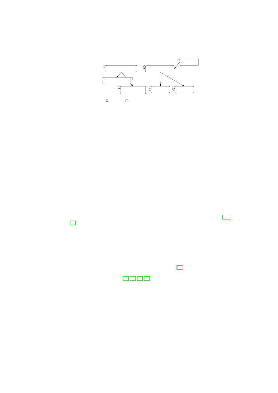
CHAPTER 3. UNIFIED POLICY ENFORCEMENT FOR VIRTUAL DATA CENTERS23
Compartment Manager
TVD Proxy
TVD Master
Network Manager
(sub-proxy)
Storage Manager
(sub-proxy)
Virtual Device Manager
Integrity Manager
TVD Component
Security Service
Figure 3.1: TVD Components and Security Services.
tion with the TVD components. Most importantly, the compartment manager service
manages the life-cycle of VMs in both para-virtualized and fully virtualized modes.
This service works in collaboration with the TVD Proxy to admit VMs into TVDs.
The integrity manager service implements Trusted Computing extensions and assists
the TVD Proxy in host pre-admission and VM admission control. The virtual network
manager and virtual storage manager services are invoked by the TVD Proxy. They
implement resource virtualization technologies and enforce parts of the high-level TVD
policies that are relevant to their operation. Lastly, the virtual device manager service
handles the secure resource allocation and setup of virtual devices assigned to each
VM.
Our TVD infrastructure is geared towards automated deployment and enforcement
of security policies specified by the TVD Master. Automated refinement and transla-
tion of high-level policies into low-level configurations are of particular interest. For
example, for information flow between two hosts in a trusted data center environment,
other mechanisms need to be in place than for a flow between two hosts at opposite
ends of an untrusted WAN link. In the latter case, the hosts should be configured to
allow communication between them only through a VPN tunnel.
Another important consideration is policy conflict detection and resolution [127,
76]. In fact, conflicting high-level policies (e.g., a connection being allowed in the
inter-TVD policy but disallowed in the intra-TVD policy) can potentially result in an
incorrect configuration of the underlying infrastructure. We cannot solely rely on the
TVD owner to specify conflict-free policies. It is important to detect policy conflicts
and provide feedback to the owner in case one is detected. In the present prototype,
policy refinement is performed manually. The result is a set of configuration files that
we use for configuring the security services at the policy enforcement layer (e.g., the
virtual networking infrastructure). In future work, we will investigate the automation
of this step using, for example, the IETF policy model [91] and various graph-based
mechanisms from the literature. We will also investigate different techniques for re-
solving conflicting policies [33, 17, 32, 38].
3.2
Virtual Networking Infrastructure
Virtual networking (VNET) technologies enable the seamless interconnection of VMs
that reside on different physical hosts as if they were running on the same machine.
In our TVD framework, we employ multiple technologies, including virtual switches,
Ethernet encapsulation, VLAN tagging, and VPNs, to virtualize the underlying net-
work and securely group VMs that belong to the same TVD. A single private virtual
network is dedicated to each TVD, and network separation is ensured by connecting
OpenTC Document D05.6/V01 – Final R7628/2009/01/15/OpenTC Public (PU)
24
OpenTC D05.6 – Final Report of OpenTC Workpackage 5
VM
VM
Eth
er
IP
Host C
Host D
Host A
VPN
WAN
WAN
vSwitch
VM
VM
VM
VM
VM
VM
VM
VM VM
VM
vSwitch
VM
VM
Tag
ge
r
vSwitch
Eth
er
IP
VLAN Switch
Host B
VM
VM
Tag
ge
r
vSwitch
VPN
Tag
ge
r
Eth
er
IP
Eth
er
IP
VPN
Eth
er
IP
VPN
vSwitch
VPN
Figure 3.2: General vSwitch Architecture.
the VMs at the Ethernet level. Logically speaking, we provide a separate “virtual
infrastructure” for each TVD in which we control and limit the sharing of network re-
sources (such as routers, switches) between TVDs. This also provides the TVD owner
with the freedom to deploy a wide range of networking solutions on top of the TVD
network infrastructure. Network address allocations, transport protocols, and other ser-
vices are then fully customizable by the TVD owner and work transparently as if the
VMs were in an isolated physical network. To maintain secrecy and confidentiality of
network data (where necessary), network communication is established over encrypted
VPN tunnels. This enables the transparent use of untrusted networks between physical
hosts that contain VMs within the same TVD to provide a seamless view of the TVD
network.
In this section, we introduce the technologies we use to implement a security-
enhanced VNET infrastructure for TVD owners. The concept of virtual switching is
central to our architecture, which is then protected by existing VPN technologies that
provide data confidentiality and integrity where needed. The VNET infrastructure acts
as the local enforcer of VNET policies. As described in Section 2.3.2, these policies
are based on the high-level TVD policies and translated into network configurations by
the TVD Proxy. The Proxy then deploys the whole VNET infrastructure with respect
to the translated configuration.
3.2.1
Virtual Switching
The virtual switch (vSwitch) is the central component of the virtual networking in-
frastructure and operates similarly to a physical switch. It is responsible for network
virtualization and isolation, and enables a virtual network to span multiple physical
hosts. To do so, the vSwitch uses EtherIP [52] and VLAN tagging [49] to insert VLAN
membership information into every network packet. The vSwitch also implements the
necessary address-mapping techniques to direct packets only to those machines that
host member VMs. Virtual switches provide the primitives for implementing higher-
level security policies for networking and are configured by the higher-level TVD man-
agement layer.
OpenTC Document D05.6/V01 – Final R7628/2009/01/15/OpenTC Public (PU)

CHAPTER 3. UNIFIED POLICY ENFORCEMENT FOR VIRTUAL DATA CENTERS25
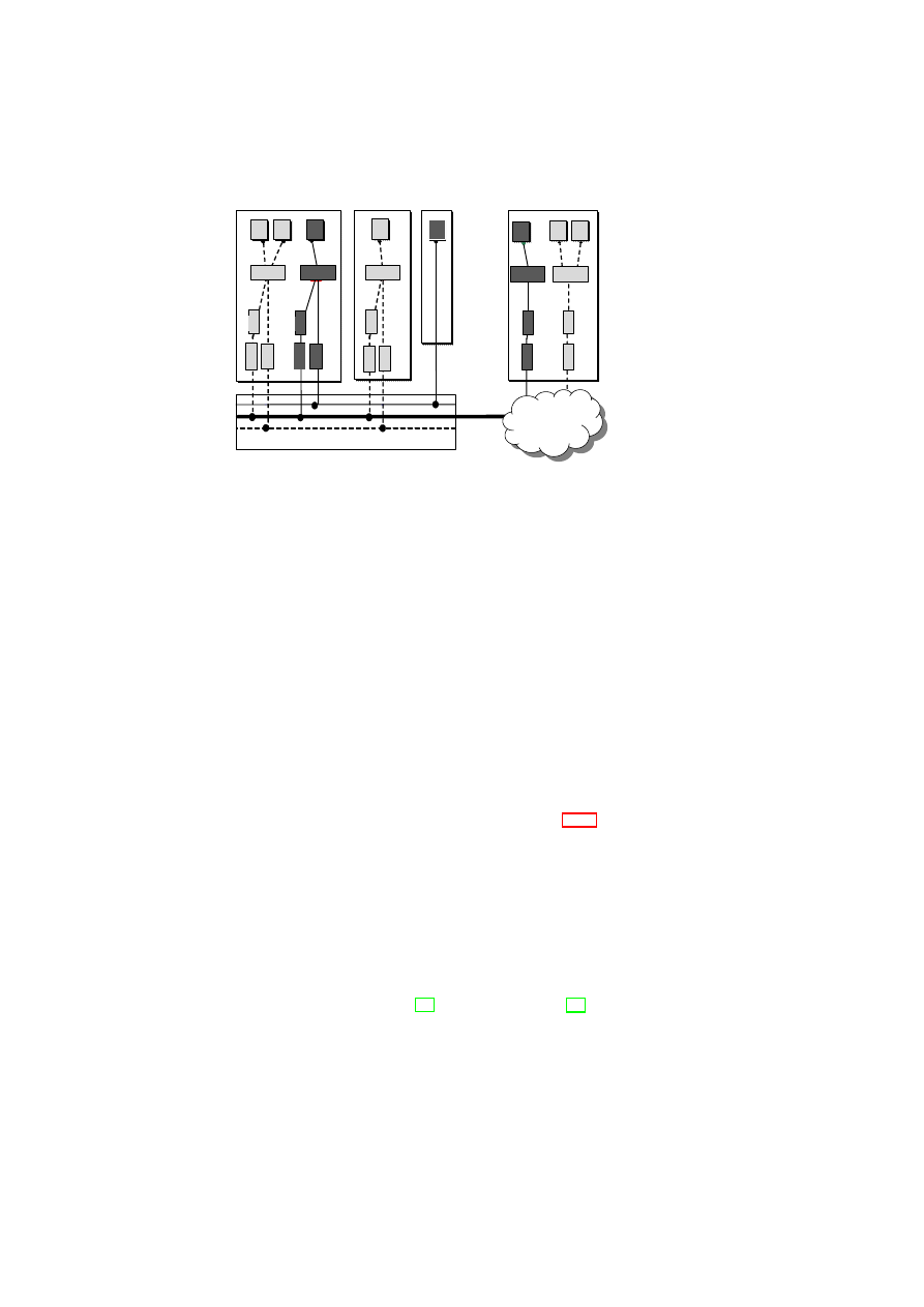
Figure 3.2 illustrates an example architecture in which physical machines host mul-
tiple VMs with different TVD memberships (the light and dark shades indicate dif-
ferent TVDs). Hosts A, B, and D are virtualized machines, whereas Host C is non-
virtualized. Furthermore, Hosts A, B, and C reside on the same LAN, and thus can
communicate directly using the trusted physical infrastructure without further protec-
tion (e.g., traffic encryption). For example, the light VMs hosted on Hosts A and B are
inter-connected using the local VLAN-enabled physical switch. In this case, the physi-
cal switch separates the TVD traffic from other traffic passing through the switch using
VLAN tags. Similarly, the dark VMs hosted on Host A and the non-virtualized Host
C are seamlessly inter-connected using the local switch. In contrast, connections that
require IP connectivity are routed over the WAN link. The WAN cloud in Figure 3.2
represents the physical network infrastructure able to deal with TVD-enabled virtual
networks; it can include LANs with devices capable of VLAN tagging and gateways
to connect the LANs to each other over (possibly insecure) WAN links. For connec-
tions that traverse untrusted medium, we employ EtherIP encapsulation to denote TVD
membership and additional security measures (such as encryption) to ensure compli-
ance with the confidentiality and integrity requirements.
3.2.2
Virtual Private Networking
In Figure 3.2, VMs hosted on Host D are connected to the other machines over a
WAN link. A practical setting in which such a connection might exist would be an
outsourced remote resource connected to the local data center through the Internet. As
an example, lightly shaded VMs on Host D connect to the lone VM on Host B over
this untrusted link. In this setting, we use a combination of EtherIP encapsulation and
VPN technology to ensure the confidentiality and integrity of the communication. To
do so, we use point-to-point VPN tunnels with OpenVPN that are configured via the
TVD Proxy from the TVD policies. This enables reconfiguration of the topology and
the involved VPNs within a TVD from a single administration point, the TVD Master.
TVD policies distributed from the TVD Master to the TVD Proxy also include the
secret key for the VPN along with other VPN-specific settings. On a physical host, the
VPN’s endpoint is represented as a local virtual network interface (vif) that is plugged
into the appropriate vSwitch controlled by the TVD Proxy. The vSwitch then decides
whether to tunnel the communication between VMs, and if so, uses the VPN module
to establish the tunnel and access the VPN secret for traffic encryption and decryption.
3.3
Virtual Storage Infrastructure
We focus on a simplified security management of virtualized storage. Broadly speak-
ing, storage virtualization abstracts away the physical storage resource(s). It is desir-
able to allow a storage resource to be shared by multiple host computers, and also to
provide a single storage device abstraction to a computer irrespective of the underly-
ing physical storage, which may be a single hard disk, a set of hard disks, a Storage
Area Network (SAN), etc. To satisfy both requirements, storage virtualization is typ-
ically done at two levels. The first level of virtualization involves aggregating all the
(potentially heterogeneous) physical storage devices into one or more virtual storage
pools. The aggregation allows more centralized and convenient data management. The
second level of virtualization concerns the unified granularity (i.e., blocks or files) at
OpenTC Document D05.6/V01 – Final R7628/2009/01/15/OpenTC Public (PU)

26
OpenTC D05.6 – Final Report of OpenTC Workpackage 5
Consolidation
Access Control & Encryption
TVD A
TVD B
TVD C
Heterogeneous
Physical Storage
Per-TVD
Raw Storage
Per-TVD
Virtual Storage
TVD A
TVD B
TVD C
Metadata
Figure 3.3: Security Enforcement for Virtualized Storage.
which data in each pool is presented to the higher-level entities (operating systems,
applications, or VMs).
Figure 3.3 shows our storage security enforcement architecture, in which existing
heterogeneous physical storage devices are consolidated into a joint pool. This vir-
tual storage pool is then subdivided into raw storage for each TVD. Each raw storage
volume has an owner TVD that determines its policy (indicated by the labels TVD
A, TVD B, and TVD C at the per-TVD raw storage layer in the figure). In addition,
when a volume shall be shared among multiple TVDs, there is also a set of member
TVDs associated with it. The access control and encryption layer helps enforce the
storage-sharing policy defined by the owner TVD, e.g., enforcing read, write, create,
and update access permissions for the member TVDs. This layer is a logical layer that
in reality consists of the virtual storage managers (part of the security services) located
on each physical platform. The virtual storage manager on each physical platform is
responsible for enforcing the owner TVD’s storage security policies (see Section 2.3.3)
on these volumes. If a certain intra-TVD security policy requires confidentiality and
does not declare the medium as trusted, the disk is encrypted using a key belonging to
the owner TVD.
1
If conditions for (re-)mounting a disk have been defined, the disk is
also encrypted and the key is sealed against the TCB while including these conditions
into the unsealing instructions. The policy and meta-data are held on a separate raw
volume that is only accessible by the data center infrastructure.
An administrator of a domain may request that a disk be mounted to a particular
VM in a particular mode (read/write). In Xen, the disk is usually mounted in the
management machine Domain-0 as a back-end device and then accessed by a guest
VM via a front-end device. The virtual storage manager on the platform validates the
mount request against the policies of both the TVD the VM is part of and the owner
TVD for the disk. Once mounted, appropriate read-write permissions are granted based
on the flow control policy for the two TVDs, e.g., read access is granted only if the
policies specified in the disk policy matrix allow the VM’s TVD such an access to the
disk belonging to the owner TVD.
3.4
TVD Admission Control
When a VM is about to join a TVD, different properties will be verified by the local
TVD Proxy to ensure that policies of all the TVDs that the VM is currently a member
of as well as of the TVD that it wants to join are not violated. If the verification is
successful, then the VM will be connected to that TVD. The TVD admission control
1
For efficiency reasons, we currently do not provide integrity protection.
OpenTC Document D05.6/V01 – Final R7628/2009/01/15/OpenTC Public (PU)

CHAPTER 3. UNIFIED POLICY ENFORCEMENT FOR VIRTUAL DATA CENTERS27
protocol is the procedure by which the VM gets connected to the TVD. In the case of
a VM joining multiple TVDs, the admission control protocol is executed for each of
those TVDs. We now describe the steps of the protocol.
We assume that the computing platform that executes the VM provides mechanisms
that allow remote parties to convince themselves about its trustworthiness. Example
mechanisms include trusted (authenticated) boot and the remote attestation protocol
(see Section 4.2) based on TPM technology.
TVD Proxy Initialization Phase:
To allow a VM to join a TVD, the platform host-
ing the VM needs access to the TVD policy, and upon successful admission, to TVD
secrets, such as the VPN key. For this purpose, TVD Proxy services are started on the
platform for each TVD whose VMs may be hosted. The TVD Proxy can be started at
boot time of the underlying hypervisor, by a system service (TVD Proxy Factory), or
by the VM itself, as long as the TVD Proxy is strongly isolated from the VM.
Pre-Admission Phase:
When a VM wants to join a TVD that is going to be hosted
on the platform for the first time, the TVD Master has to establish a trust relationship
with the platform running the VM, specifically with the TVD Proxy. We call this
step the pre-admission phase. It involves the establishment of a trusted channel (see
Section 4.3) between the TVD Master and the TVD Proxy (or the TVD Proxy Factory).
The trusted channel allows the TVD Master to verify the integrity of the TVD Proxy
(Factory) and the underlying platform. After the trusted channel has been established
and the correct configuration of the Proxy has been verified, the TVD Master can send
the TVD policies and credentials (such as a VPN key) to the TVD Proxy.
Admission Control Phase:
The Compartment Manager (part of the platform secu-
rity services shown in Figure 3.1) is responsible for starting new VMs. The Compart-
ment Manager loads the VM configuration and enforces the security directives with
the help of the Integrity Manager (also part of the platform security services shown in
Figure 3.1). The security directives may include gathering the VM state information,
such as the VM configuration, kernel, and disk(s) that are going to be attached to the
VM.
If the VM configuration states that the VM should join one or more TVDs, then the
Compartment Manager interacts with the corresponding TVD Proxy(ies) and invokes
TPM functions to attest the state of the VM. The TVD Proxy verifies certain properties
before allowing the VM to join the TVD. More concretely, the TVD Proxy has to
ensure that
•
the VM fulfills the integrity requirements of the TVD;
•
the information flow policies of all TVDs the VM will be a member of will not
be violated;
•
the VM enforces specific information flow rules between TVDs if such rules are
required by the TVD policy, and that
•
the underlying platform (e.g., the hypervisor and attached devices) fulfills the
security requirements of the TVD.
Platform verification involves matching the security requirements with the platform’s
capabilities and mechanisms instantiated on top of these capabilities. For example,
OpenTC Document D05.6/V01 – Final R7628/2009/01/15/OpenTC Public (PU)

28
OpenTC D05.6 – Final Report of OpenTC Workpackage 5
suppose that data confidentiality is a TVD requirement. Then, if hard disks or network
connections are not trusted, additional mechanisms, such as block encryption or VPN
(respectively), need to be instantiated to satisfy the requirement.
TVD Join Phase:
If the VM and the provided infrastructure fulfill all TVD require-
ments, a new network stack is created and configured as described in Section 3.2. Once
the Compartment Manager has started the VM, it sends an attach request to the corre-
sponding TVD vSwitch. Once the VM is connected to the vSwitch, it is a member of
the TVD.
OpenTC Document D05.6/V01 – Final R7628/2009/01/15/OpenTC Public (PU)
Chapter 4
Background and Related Work
In order to put our work in context we survey key concepts that underlie our approach.
Section 4.1 presents the TVD concept, which can be thought of as a virtualization
of today’s security zones while making security requirements explicit. Section 4.2
describes Trusted Computing concepts. The core of this concept is a security hardware
device called Trusted Platform Module that guarantees certain security functionalities
in spite of attacks. We finally survey related work on trusted channels in Section 4.3
and on secure virtual networking in Section 4.4.
4.1
Overview of Trusted Virtual Domains
Bussani et al. [16] introduced the concept of TVDs. A Trusted Virtual Domain con-
sists of a set of distributed Virtual Processing Elements (VPEs), storage for the VPEs,
and a communication medium interconnecting the VPEs [16, 62, 45]. The TVD pro-
vides a policy and containment boundary around those VPEs. VPEs within each TVD
can usually exchange information freely and securely with each other. At the same
time, they are sufficiently isolated from outside VPEs, including those belonging to
other TVDs. Here, isolation loosely refers to the requirement that a dishonest VPE in
one TVD cannot exchange information (e.g., by sending messages or by sharing stor-
age) with a dishonest VPE in another TVD, unless the inter-TVD policies explicitly
allow such an exchange. There is a TVD infrastructure (for each TVD) that provides a
unified level of security to member VPEs, while restricting the interaction with VPEs
outside the TVD to pre-specified, well-defined means only. Unified security within a
virtual domain is obtained by defining and enforcing membership requirements that the
VPEs have to satisfy before being admitted to the TVD and for retaining membership.
Each TVD defines rules regarding information exchange with the outside world, e.g.,
restrictions regarding in-bound and out-bound network traffic.
Figure 1.1 shows customer VMs as VPEs belonging to
TVD
1
spanning two plat-
forms (contained in the dashed boxes). The Master (
TVD1 Master
) and Proxy compo-
nents (
Proxy1
on each platform) are part of the TVD infrastructure, which we describe
in detail in Section 3.1. The TVD Master is the orchestrator of the TVD deployment
and configuration. There is one TVD Proxy for each platform hosting VMs belonging
to that TVD. If the platform hosts VMs belonging to multiple TVDs, then there are
multiple TVD proxies on that platform, one per TVD. The TVD Proxy on a platform
is configured by the TVD Master and can be thought of as the local TVD policy en-
29
30
OpenTC D05.6 – Final Report of OpenTC Workpackage 5
forcer. VMs belonging to the same TVD can usually exchange information freely with
each other unless restricted by VM-level policies. For example, traffic originating from
VM
A
1
or
VM
A
2
on Host A is routed to
VM
Bi
(
i
= 1
,
· · ·
,
4
) on Host B without any
restrictions. Information exchange among TVDs can be allowed; however, it is subject
to the network and storage policies stated by each TVD Master and locally enforced by
each TVD Proxy.
4.2
Trusted Computing – The TCG Approach
It is important to have reliable mechanisms for a system to reason and verify the trust-
worthiness (i.e., compliance with a certain security policy) of a peer endpoint (local
or remote). A recent industrial initiative towards realizing such a mechanism was put
forward by the Trusted Computing Group (TCG) [113], a consortium of a large number
of IT enterprises that proposes a new generation of computing platforms that employs
both supplemental hardware and software (see, e.g., [81, 100]). The TCG
1
has pub-
lished several specifications on various concepts of trusted infrastructures [121].
The Trusted Platform Module
The core component the TCG specifies is the Trusted
Platform Module (TPM). Currently, the widespread implementation of the TPM is a
small tamper-evident chip
2
that implements multiple roots-of-trust [122, 120], e.g., the
root-of-trust for reporting and the root-of-trust for storage. Each root-of-trust enables
parties, both local and remote, to place trust on a TPM-equipped platform that the lat-
ter will behave as expected for the intended purpose. By definition, the parties trust
each root-of-trust, and therefore it is essential that the roots-of-trust always behave as
expected. Given that requirement, a hardware root-of-trust – especially one that is com-
pletely protected from software attacks and tamper-evident against physical attacks, as
required by the TPM specification – is assumed to provide a better protection than
software-only solutions.
Attestation and Integrity Verification
The Trusted Computing features we leverage
in this paper are protection of keys, secure recording of integrity measurements, attes-
tation, and sealing. Integrity verification mechanisms enable a remote party to verify
whether system components conform to certain security policies. Measurement of a
component involves computing the SHA-1 hash of the binary code of that component.
In particular, each software component in the Trusted Computing Base (TCB) is first
measured and then its measurement recorded before control is passed to it. The hash
values are then appended to a hash chain, which is kept in special protected registers
called Platform Configuration Registers (PCRs), thus acting as accumulators for mea-
surements. Recording a measurement means appending it to the hash chain by PCR
extend operation
3
. The sequence of measured values are also stored in a measurement
log
4
, external to the TPM.
1
TCG’s claimed role is to develop, define, and promote open and vendor-neutral industry specifications
for Trusted Computing, including hardware building blocks and software interface specifications across mul-
tiple platforms and operating environments.
2
Many vendors already ship their platforms with TPMs (mainly laptop PCs and servers).
3
Extending of PCR values is performed as follows:
PCR
i
+1
:= SHA1(
PCR
i
|
I
)
, with the old register
value
PCR
i
, the new register value
PCR
i
+1
, and the input
I
(e.g. a SHA-1 hash value).
4
Since each PCR holds only the digest of (part of) the chain of trust, keeping the list of all measured
values is required if afterwards, during the attestation process, a remote party wants to identify each measured
component.
OpenTC Document D05.6/V01 – Final R7628/2009/01/15/OpenTC Public (PU)

CHAPTER 4. BACKGROUND AND RELATED WORK
31
Attestation refers to the challenge-response-style cryptographic protocol for a re-
mote party to query the recorded platform measurement values and for the platform to
reliably report the requested values. The verifier first sends a challenge to the platform.
The platform invokes the
TPM
_
Quote
command with the challenge as a parameter.
The invocation also carries an indication of which PCRs are of interest. The TPM
returns a signed quote containing the challenge and the values of the specified PCRs.
The TPM signs using an Attestation Identity Key (AIK), whose public key is certified
by a third party that the verifier trusts, called Privacy CA in TCG terminology. The
platform then replies to the verifier with the signed quote along with the AIK public
key certificate and the log information that is necessary to reconstruct the platform’s
configuration. Based on the reply, the verifier can decide whether the platform is in an
acceptable state.
Sealing is a TPM operation that is used locally to ensure that a certain data item
is accessible only under specific platform configurations reflected by PCR values. The
unsealing operation will reveal the data item only if the PCR values at the time of the
operation match the PCR specified values at the time of sealing.
A more general and flexible extension to the binary attestation is property-based
attestation [96, 90, 69]: Attestation should only determine whether a platform config-
uration or an application has a desired property. However, our prototype is still using
binary attestation.
In [47], the authors propose semantic remote attestation using language-based
trusted VM to remotely attest high-level program properties. The general idea is to
use a trusted VM (TrustedVM) that verifies the security policy of another virtual ma-
chine on a given host.
In [77], [78], and [79], the authors propose a software architecture based on Linux
providing attestation and binding. The architecture binds short-lifetime data (e.g., ap-
plication data) to long-lifetime data (e.g., the Linux kernel) and allows access to that
data only if the system is compatible with a security policy certified by a security ad-
ministrator.
4.3
Trusted Channels
The standard approach for establishing secure channels over the Internet is to use secu-
rity protocols such as Transport Layer Security (TLS) [27] or Internet Protocol Secu-
rity (IPSec) [63]), which aim at assuring confidentiality, integrity, and freshness of the
transmitted data as well as authenticity of the endpoints involved. However, as men-
tioned before, secure channels do not provide any guarantees about the integrity of the
communication endpoints, which can be compromised by viruses or Trojans. Based
on security architectures that deploy Trusted Computing functionality, one can extend
these protocols with integrity reporting mechanisms (e.g., the TLS extension proposed
in [42, 9]). Such extensions can be based on binary attestation or on property-based
attestation.
4.4
Secure Network Virtualization
Previous work on virtualizing physical networks can be roughly grouped into two cat-
egories: those based on Ethernet virtualization and those based on TCP/IP-level virtu-
alization. Although both categories include a substantial amount of work, few of these
OpenTC Document D05.6/V01 – Final R7628/2009/01/15/OpenTC Public (PU)

32
OpenTC D05.6 – Final Report of OpenTC Workpackage 5
studies have an explicit focus on security.
A secure network virtualization framework was proposed by Cabuk et al. [18] for
realizing the network flow aspects of TVDs. The focus of [18] is a security-enhanced
network virtualization, which (1) allows groups of related VMs running on separate
physical machines to be connected together as though they were on their own separate
network fabric, and (2) enforces intra-TVD and inter-TVD security requirements such
as confidentiality, integrity, and inter-TVD flow control. This has been achieved by an
automatic provisioning of networking components such as VPNs, Ethernet encapsula-
tion, VLAN tagging, and virtual firewalls.
A second concept for managing VLAN access has been proposed by Berger et al. in
[14]. Both papers contain similar concepts for managing VLANs inside the data center
with some differences. The work of Berger et al. has more of a focus on integrity
assurance using Trusted Computing. The work of Cabuk et al [18] allows provisioning
of secure virtual networking even if no VLAN infrastructure is present.
OpenTC Document D05.6/V01 – Final R7628/2009/01/15/OpenTC Public (PU)

Part II
Building Blocks of the OpenTC
Security Architecture
33

Chapter 5
Policy Enforcement and
Compliance Proofs for Xen
Virtual Machines
Bernhard Jansen, HariGovind V. Ramasamy, Matthias Schunter (IBM)
5.1
Introduction
Hardware virtualization is enjoying a resurgence of interest fueled in part by its cost-
saving potential in data centers. By allowing multiple virtual machines to be hosted
on a single physical server, virtualization helps improve server utilization, reduce man-
agement and power costs, and control the problem of server sprawl.
We are interested in the security management of virtual machines, i.e., the pro-
tection, enforcement, and verification of the security of virtual machines. Security
management is a non-trivial problem even in traditional non-virtualized environments.
Security management of virtual machines (VMs) is even more complicated because the
virtual machines hosted on a given physical server may belong to different virtual orga-
nizations, and as a result, may have differing security requirements. Protecting a VM
against security attacks may be complicated by inadequate isolation of the VM from
other VMs hosted on the same server. Verifying the security of a VM may be compli-
cated by confidentiality requirements, which may dictate that the information needed
for verification of a VM’s configuration should not divulge configuration information
of other co-hosted VMs.
We address two main problems relating to security management, particularly in-
tegrity management, of VMs: (1) protecting the security policies of a VM against
modification throughout the VM’s life cycle, and (2) verifying that a VM is com-
pliant with specified security requirements. We describe a formal model that gen-
eralizes integrity management mechanisms based on the Trusted Platform Module
(TPM) [120] to cover VMs (and their associated virtual devices) and a wider range
of security policies (such as isolation policies for secure device virtualization and mi-
gration constraints for VMs). On TPM-equipped platforms, system compliance can
be evaluated by checking TPM register values. Our model allows finer-grained com-
pliance checks by handling policies that can be expressed as predicates on system log
34
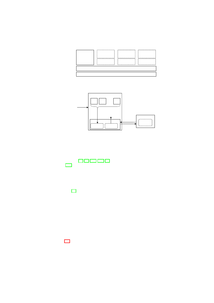
CHAPTER 5. POLICY ENFORCEMENT AND COMPLIANCE
35
Physical Hardware
Management
of security,
devices,
VMs, and I/O
Dom0
GuestOS
User
Software
DomU 1
GuestOS
User
Software
DomU 2
GuestOS
User
Software
DomU 3
VMM Core
Figure 5.1: Xen virtual machine architecture
TCB
policy
log
integrity
state
conditional
release
of secrets
VM
sealing or
attestation
request
response
User or Verifier
integrity
requirements
predicate
Π
Π
System
log
repository
secret
repository
VM
VM
. . . .
Figure 5.2: System model for integrity management
entries. Verifying compliance involves showing that the system integrity state, as re-
flected by secure write-only logs, satisfies certain conditions. We build on previous
work by others [39, 45, 101, 104, 13] who have used the Trusted Platform Module
(TPM) [120] to protect the integrity of the core virtual machine monitor (VMM) and to
reliably isolate VMs. Based on the formal model, we describe an integrity architecture
called PEV (which stands for protection, enforcement, and verification) and associated
protocols. The architecture incorporates integrity protection and verification as part of
the virtualization software itself, and at the same time enhances its policy enforcement
capabilities. We describe a prototype realization of our architecture using the Xen
hypervisor [11]. We demonstrate the policy enforcement and compliance checking
capabilities of our prototype through multiple use cases.
Our generalized integrity management mechanisms are both extensible and flexi-
ble. Extensibility means that it is possible to guarantee compliance even if new virtual
devices are attached to the VMs. Flexibility means that the verifier is able to spec-
ify which aspects of the enforced security policies are of interest, and obtain only the
information corresponding to those aspects for validation of system compliance.
5.2
Formal Integrity Model for Virtual Machines
Figure 5.2 shows our system model for integrity management. At a high level, the
system consists of VMs and a TCB, and is configured through policies. The TCB peri-
odically logs the integrity state of the rest of the system. The log repository contains a
record of the integrity history of the system, and is secure write-only, i.e., log entries,
once written, cannot be modified or removed by any entity in the rest of the system.
OpenTC Document D05.6/V01 – Final R7628/2009/01/15/OpenTC Public (PU)

36
OpenTC D05.6 – Final Report of OpenTC Workpackage 5
…
…
(
id, type, log
)
(
id, type, log
)
(
id
1
, type
1
, log
1
)
(
id
1
, type
1
, log
1
)
(
id
11
, type
11
, log
11
)
(
id
11
, type
11
, log
11
)
(
id
111
, type
111
, log
111
)
(
id
111
, type
111
, log
111
)
(
id
21
, type
21
, log
21
)
(
id
21
, type
21
, log
21
) (
id
2
n
, type
2
n
, log
2
n
)
(
id
2
n
, type
2
n
, log
2
n
)
(
id
2
, type
2
, log
2
)
(
id
2
, type
2
, log
2
)
Figure 5.3: Tree
T
of log entries
The log data includes the list of software components, configuration parameters, poli-
cies, and any updates to them. The log contents are useful in evaluating compliance
with those security properties that can be expressed as predicates on the contents. The
compliance proof involves showing that correct policies and healthy policy enforce-
ment mechanisms are in place. The TCB also provides conditional release of secrets,
where the condition is expressed as predicates on the log data. That allows a sensitive
data item and a condition to be stored such that the data item is released only if the log
data satisfies the condition specified.
For flexibility and extensibility, the log data is stored in a tree structure instead
of a monolithic log file. The log tree
T
is shown in Figure 5.3. Each tree node is a
triple containing log data for one system component. To keep the tree size manageable,
only those components that have an impact on the system’s integrity or those that are
of interest from an integrity verification point of view are represented in the log tree.
A triple for a component
k
contains an identifier
id
k
, a component type
type
k
, and a
vector
log
k
of log values. Sub-components are modeled as children of a node. The tree
can be extended by adding or removing children nodes. For example, the addition of a
new virtual device to a VM can be easily reflected in the log tree by adding a new node
as a child of the sub-tree that corresponds to the VM.
The integrity requirements of a user or verifier are modeled by
Π(
p
(
T
))
, where
Π
is a predicate and
p
()
is a projection function. We introduce the notion of a projection
function, denoted by
p
()
, to model the specific aspects of the system’s integrity state
that is of interest to a user or verifier. For example, a verifier may be interested only in
a disk’s access control list and not the actual disk contents. When applied on the log
tree, the function returns a subset of the tree nodes and a subset of the vector elements
from the log vector of each node. Formally,
p
(
T
) =
{
l
k
}
, where
l
k
∈
log
k
, and
(
id
k
, type
k
, log
k
)
∈ T
.
We now use our formal model to generalize TPM-based integrity protection and
verification. We also enhance our model by adding access control to the log contents.
5.2.1
Generalized Sealing to Protect Integrity
A TPM-equipped system can seal a data item, i.e., the system can encrypt the data item
and bind it to the system configuration prevalent at the time of sealing. The system
configuration is reflected by the contents of a specified subset of the TPM’s PCRs. The
data item may be a key generated by the TPM itself or something generated outside the
TPM. Decryption of the data item, called unsealing, is possible only when the system
configuration (reflected by the contents of the same subset of PCRs) is the same as that
at the time of sealing.
We generalize sealing for protecting the integrity of a sensitive data item
d
by mak-
ing
d
inaccessible to the system (or some component) unless specified integrity re-
OpenTC Document D05.6/V01 – Final R7628/2009/01/15/OpenTC Public (PU)

CHAPTER 5. POLICY ENFORCEMENT AND COMPLIANCE
37
quirements are met. We use two operations,
seal
and
unseal
, to model the concept of
generalized sealing. Let
T
x
denote the log tree at time
t
x
. The
seal
operation, per-
formed at time
t
s
, takes as input the data item
d
, a projection function
p
()
, a sealing
predicate
Π
, and the public part
K
p
of an encryption key
K
. The operation logs
p
()
and
Π
, and encrypts
d
using
K
p
to produce the encrypted output
e
. Thus, the contents
of
T
s
include
p
()
and
Π
. The
unseal
operation, performed at time
t
u
(where
t
u
> t
s
),
takes as input
e
and
T
u
, and outputs
d
iff the condition
Π(
p
(
T
u
))
holds. In other words,
the private part of the key
K
used for decrypting
e
is revealed iff the condition holds.
Here,
p
()
and
Π
are retrieved from the log. A simple sealing predicate may just com-
pare the result of
p
(
T
u
)
with a reference value (e.g.,
p
(
T
s
)
). A more complex predicate
may extract the high-level properties of the system from
p
(
T
u
)
and compare them with
desired properties (similar to property-based attestation [90, 20, 47]).
One can easily see that our generalized sealing concept covers the special case of
TPM sealing. For TPM sealing,
T
u
consists of the values in the PCRs; the projection
function
p
()
specifies the subset of PCRs whose values are of interest for assessing the
system’s integrity; the sealing predicate
Π
checks whether their values at the time of
unsealing are the same as at the time of sealing.
5.2.2
Generalized Attestation to Verify Integrity
A TPM-equipped system can use the TPM to engage in a challenge-response style
cryptographic protocol, called attestation, with a verifier. The protocol allows the ver-
ifier to query and reliably obtain the measurement values for the system stored in the
PCRs of the TPM. Reliable reporting of the measurement values is due to the signing
of the values by the TPM, which is trusted by the verifier. Based on these values, the
verifier can assesses the integrity state and the trustworthiness of the system.
We generalize attestation so that the verifier can specify which aspects of the sys-
tem’s integrity state are of interest to her. In our model, the attestation operation
attest
()
obtains as input a challenge
c
, an attestation predicate
Π
, a projection function
p
()
, and a secret key
K
s
. The operation outputs a signed message
sign
K
s
(
f
(
p
(
T
))
, c
)
.
Our attestation operation is a generalization of both binary and property-based at-
testation [90, 20, 47]. For binary attestation, the predicate
Π
is simply the identity
function, i.e.,
Π(
x
) =
x
, and the result of attestation is simply the signature on the
result of the projection function applied on the log tree. TPM attestation is a special
case of binary attestation in which
T
simply consists of the values in the PCRs and
the projection function
p
()
specifies a subset of PCRs. For property-based attestation,
the predicate
Π
extracts high-level properties from the result of the projection function
applied on the log tree.
Whereas previous works such as the Integrity Measurement Architecture (IMA) of
of Sailer et al. [104] provide a good way of checking the hash of software binaries,
our generalized attestation enables better assessment of the run-time behavior of the
system. In this respect, our model has goals similar to those of Haldar et al. [47]. How-
ever, unlike Haldar et al. who focus on attesting the behavior of a software application,
our model has a focus on VMs and virtual devices. For example, our attestation oper-
ation enables a verifier to check the number and type of VMs running on the system.
Because of their reliance on the Java virtual machine which runs on top of an operating
system, their TCB includes the operating system. In contrast, our TCB includes only
the VMM and underlying system layers, and is much smaller than theirs.
OpenTC Document D05.6/V01 – Final R7628/2009/01/15/OpenTC Public (PU)
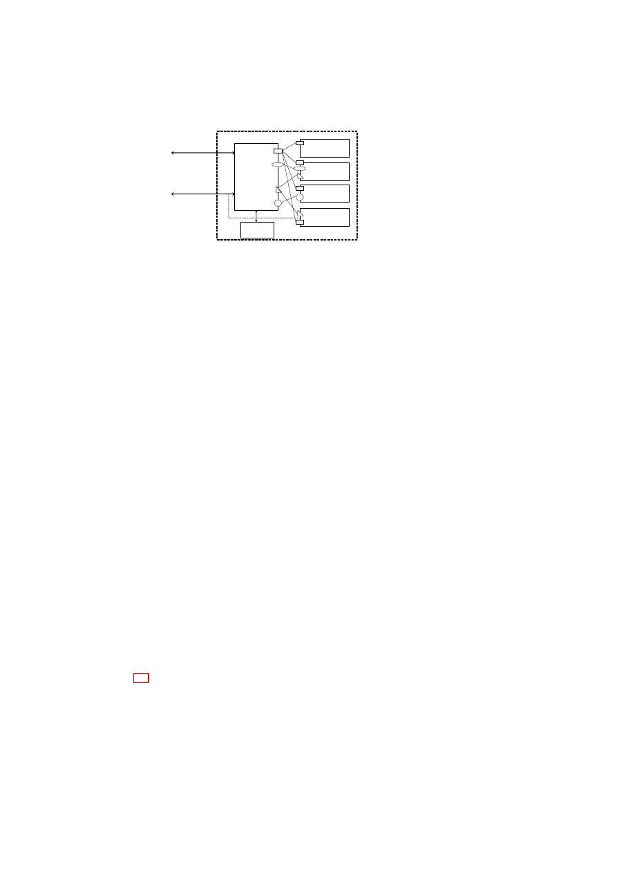
38
OpenTC D05.6 – Final Report of OpenTC Workpackage 5
Central
Integrity
Manager
Network
Integrity Manager
VMM
Integrity Manager
Devices
Integrity Manager
Storage
Integrity Manager
Attestation
Sealing
Unsealing
TCB
Predicate
Evaluator
Figure 5.4: Architecture for integrity protection and verification
5.2.3
Access Restriction
The integrity of certain aspects of the system (such as the VMM) may be important to
multiple users. Conversely, certain aspects of the system may be confidential to one
or more users, e.g., the state of a particular VM may be verified only by the users of
that VM. Hence, it is important that attestation and sealing be applied not directly on
the system state, but on appropriate projections of the state. Furthermore, if a state
that is relevant for integrity verification contains information about multiple users, it
should be possible to prove integrity without revealing the actual state. We formalize
such requirements using two concepts: access restriction specification and projection
assessment function.
Given a set of users
U
and a log tree
T
, an access restriction is specified by a
function
r
()
that assigns a subset of
U
to each vector element in each node of the
tree. The subset assigned to a given vector element in a given node is called the access
control list (ACL) for that element. Despite the potentially large number of nodes in the
log tree, ACLs can be efficiently implemented by attaching ACLs only to some nodes
and vector elements. ACLs of children nodes may be derived through inheritance of
the parent node’s ACL. Scoping rules may be used to apply an ACL to multiple vector
elements of a given node.
A projection assessment function can determine whether a given projection con-
forms to or violates access restrictions. A projection
p
(
T
)
applied by a user
u
∈
U
conforms to the access restriction specification
r
()
if the output only contains vector
elements in which
u
was contained in the ACL. Any predicate
Π
for attestation or seal-
ing can be applied on such a projection without violating the access restrictions. If the
projection does not conform to
r
()
, then prior to applying the predicate, an access filter
is used to hide those parts of
p
(
T
)
that
u
is not authorized to see.
5.3
The PEV Integrity Architecture
Figure 5.4 shows the PEV architecture for protecting, enforcing, and verifying the
integrity of VMs and virtual devices. There is a central integrity manager and compo-
nent integrity managers that are associated with individual system components such as
storage, VMM, networking, and other devices. Each component integrity manager is
responsible for the part of the log tree corresponding to the component. For example,
the storage integrity manager is responsible for maintaining the storage sub-tree of the
OpenTC Document D05.6/V01 – Final R7628/2009/01/15/OpenTC Public (PU)

CHAPTER 5. POLICY ENFORCEMENT AND COMPLIANCE
39
system log tree
T
. Hereafter, we refer to the central integrity manager as the Integrity
Manager.
The Integrity Manager has a master plug-in module for each log projection func-
tion that needs to be implemented. The module obtains state information about various
aspects of the system that may be of interest to a potential verifier or user by invoking
the appropriate component plug-in modules and aggregating their outputs. A compo-
nent plug-in module is part of the component integrity manager and reveals particular
aspects of the component’s integrity that are relevant for the projection function.
In Figure 5.4, the various master plug-in modules are attached to the Integrity Man-
ager are shown using different geometrical shapes (ovals, hexagons, triangles, and
rectangles). For example, the triangular plug-in module measures certain aspects of
system storage and the VMM, as indicated by the presence of triangular component
plug-in modules in the Storage Integrity Manager and VMM Integrity Manager. On
the other hand, the hexagonal plug-in module measures only certain aspects of sys-
tem devices. Each plug-in module has a unique identifier. The mapping between each
plug-in identifier and the functionality provided by the corresponding plug-in module
is made publicly available (e.g., through a naming service or a published table).
5.3.1
Sealing/Unsealing Protocol
At the time of sealing, the user provides the following inputs:
Data The data item to be encrypted during sealing and to be revealed later only if
certain conditions are met.
Key The sealing key whose public part is used for encrypting the data at the time of
sealing, and whose private part is revealed only if the unseal operation completes
successfully.
Identifier(s) of Plug-in Module(s) By listing the identifiers of plug-in modules, a user
can choose what aspects of the system’s integrity state are to be checked prior to
revealing the private part of the sealing key.
Predicate The predicate specifies user-defined conditions that the system’s integrity
state must satisfy at the time of unsealing in order for the private part of the
sealing key to be revealed.
Our sealing protocol requires the log projection functions (described in Sec-
tion 5.2.1) to be implemented as plug-in modules as part of the TCB. The key used
for encrypting the sensitive data item is sealed away against the state of the TCB and
a hash of the user-specified projection functions and sealing predicates. The Integrity
Manager stores the state of the TCB in PCRs that cannot be reset and the hash in a
resettable PCR (say
P CR
i
). This ensures that the TCB is aware of the conditions to
be satisfied before the key can be revealed to the user. To perform the unseal operation,
the TCB has to ensure that
P CR
i
still contains the hash of the user-specified projec-
tion function and sealing predicates. Then, the unseal operation reveals the key to the
Integrity Manager. The Integrity Manager then invokes the predicate evaluator module
(Figure 5.4) to check whether the sealing predicates (evaluated on the output of the log
projection function) are indeed satisfied. If that is the case, then the Integrity Manager
reveals the key to the user.
OpenTC Document D05.6/V01 – Final R7628/2009/01/15/OpenTC Public (PU)
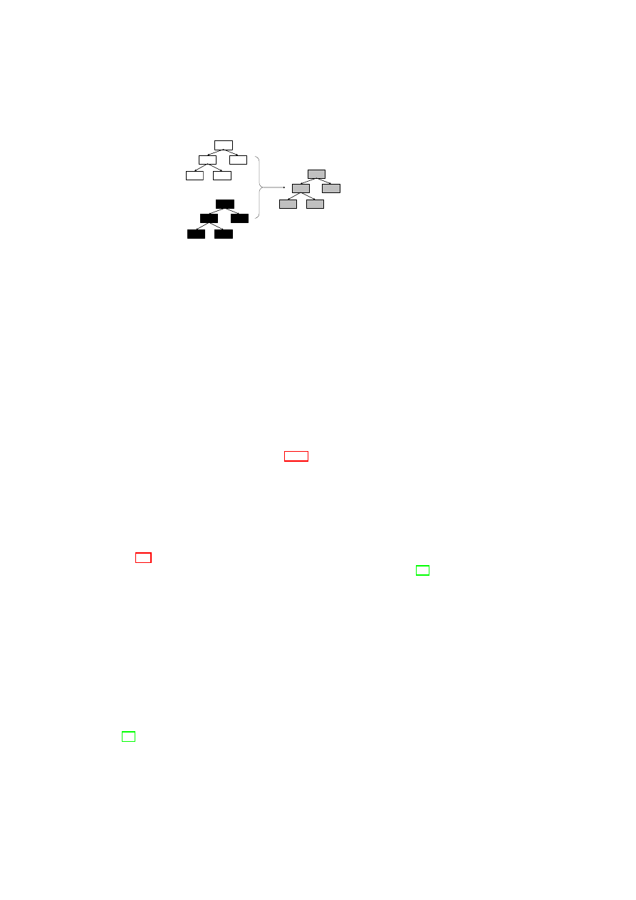
40
OpenTC D05.6 – Final Report of OpenTC Workpackage 5
N
N
1
N
2
N
11
N
12
N’
N’
1
N’
2
N’
11
N’
12
R
R
1
R
2
R
11
R
12
TT
R
R
¯
T
¯
T
T ⊗ R
T ⊗ R
Figure 5.5: Enforcing access restrictions on system state
The flexibility of our sealing protocol is due to the fact that arbitrarily complex
conditions to reveal the sealed key can be coded as plug-in modules. The extensibility
arises from the fact that new plug-in modules covering the integrity state of newly
added VMs or virtual devices can be easily added to the TCB.
5.3.2
Attestation Protocol
The verifier initiating the attestation protocol provides as input a challenge (to ensure
freshness) and the identifier(s) of plug-in module(s) that are relevant to evaluating sys-
tem compliance with the verifier’s integrity requirements. The flexibility of our attes-
tation protocol relies on the verifier being able to attest the TCB and requires the log
projection functions (described in Section 5.2.1) to be implemented as plug-in modules
as part of the TCB. The extensibility of our attestation protocols relies on the ability to
add new plug-in modules for new aspects of the system’s integrity state that the verifier
may be interested in.
5.3.3
A Blinding Technique For Enforcing Access Restrictions
Figure 5.5 shows a simple blinding technique that uses a commitment scheme to enforce
access restrictions on the log tree. Cryptographic commitment schemes [44] generally
consist of two phases. The first phase, called commit phase, is used to make a party
commit to a particular value while hiding that value from another party. It is only in the
second phase, called reveal phase, that the value is revealed to the second party. Any
commitment scheme guarantees that (a) the committed value cannot be obtained by the
second party before the reveal phase, and (b) the second party can detect whether the
value revealed is indeed the same value that was committed to in the first phase.
For simplicity, we consider blinding at the granularity of log tree nodes instead of
at the granularity of log vector elements in the tree nodes, i.e., the access restriction
specification
r
()
assigns a subset of
U
to each node of the tree. A random tree
R
is
bound to the original log tree
T
through a multi-bit commitment scheme to give the
blinded log tree
¯
T
.
R
is a tree that has the same structure as that of
T
and whose nodes
are random numbers. Existing commitment schemes such as the one by Damgard et
al. [26] or those based on one-way hash functions can be used for this purpose.
In a TPM-equipped system, logging is done by extending the PCRs with the mea-
surement values. For blinding, it is the nodes of
¯
T
that are actually logged. This
OpenTC Document D05.6/V01 – Final R7628/2009/01/15/OpenTC Public (PU)

CHAPTER 5. POLICY ENFORCEMENT AND COMPLIANCE
41
means that instead of doing the normal
TPM
_
extend
(
n
)
, a
TPM
_
extend
(
r
⊗
n
)
is
done, where
n
is a node of
T
,
r
is a node of
R
, and
⊗
denotes the commitment
operation used for hiding
n
until the reveal phase.
A projection function
p
()
that conforms to the access restrictions can be realized as
follows: when invoked at the request of user
u
,
p
()
reveals
¯
T
and only those nodes in
T
that contain
u
in their respective ACLs. Thus,
p
()
implements the reveal phase of the
multi-bit commitment scheme and reveals only those nodes in
T
that
u
is authorized
to access. Due to the guarantees of the commitment scheme, the system cannot invent
arbitrary values for the nodes in
T
without being detected by the user.
As a result of the blinding technique described above, any user
u
knows that all
components that have any effect on system integrity have been taken into consideration
in the system log tree; in addition, for those components that it is authorized to access,
u
can check whether they indeed have the acceptable configuration and state value, by
comparing with its own reference values that may be provided and certified by a trusted
third party. In particular, if the ACL for the root node is
U
(i.e., all users can access
the root node), then any user can verify overall system integrity (just from the value of
root(
T
)) without knowing the exact configuration of any individual component in the
system.
Our approach of using commitment schemes for blinding suffers from the disad-
vantage that two colluding verifiers can learn the values revealed to the other. Alternate
schemes based on zero-knowledge proofs or deniable signatures need to be investigated
to overcome this disadvantage.
5.4
Realization using Xen and Linux
Figure 5.6 shows an example implementation of our PEV architecture with the Xen hy-
pervisor using Linux for Dom0. The main components of our implementation are the
Compartment Manager (CM), Integrity Manager (IM), and the Secure Virtual Device
Manager (SVDM). All components are implemented in Dom0. The CM is responsi-
ble for the VM life cycle management. As the sole entry point for user commands, it
communicates directly with the hypervisor and orchestrates the IM and the SVDM. Ta-
ble 5.1 shows the mapping between concepts in our formal model and their realization
in our Xen prototype. XSLT is a language for transforming one XML document into
another XML document [6]. We assume that the XSLT interpreter is part of the TCB.
The
getCurrentState
()
function of the CM returns the current state of the physical
machine, which includes the list of hosted VMs, their status (active, suspended, or
hibernating), VM ownership information (e.g., the virtual organization to which a VM
belongs), the amount of free memory available, etc. Using the result of the function,
a verifier can decide whether the physical machine satisfies the integrity requirements
for performing certain actions (e.g., starting a new VM belonging to a particular virtual
organization).
The IM in our Xen prototype has a storage integrity plug-in (SIP) for measuring var-
ious disk images and files. The IM also has an Attestation & Sealing module (ASM)
that interfaces with the TPM for executing the sealing and attestation protocols (de-
scribed in Sections 5.3.1 and 5.3.2) as well as for invoking normal TPM operations,
such as
TPM
_
Quote
. The ASM invokes normal TPM operations through the TPM
Software Stack (TSS) [116], which is the standard API for accessing the functions of
the TPM.
OpenTC Document D05.6/V01 – Final R7628/2009/01/15/OpenTC Public (PU)
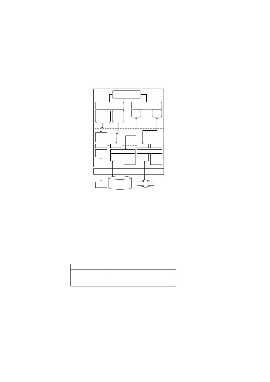
42
OpenTC D05.6 – Final Report of OpenTC Workpackage 5
Xen Hypervisor
TPM
Hard Disk
Drive (HDD)
Network
/dev/tpm
TPM
Driver
TPM
Software
Stack
HDD
Driver
DM Crypt
/dev/sda
Ethernet
Driver
virtual
network
device
backend
Bridge
brctl
eth0
Compartment
Manager
Integrity
Manager
Secure Virtual
Device Manager
virtual
disk
virtual
NIC
Attestation
& Sealing
Module
Storage
Integrity
Plug-in
Dom0
User
Space
Library
Space
Kernel
Space
virtual
block
device
backend
Figure 5.6: Realization using Xen and Linux
Model
Xen-based Prototype
Projection
p
()
component measurement plug-in
Predicate
Π
XSLT stylesheet
Access Filter
XSLT stylesheet
Table 5.1: From model to implementation
OpenTC Document D05.6/V01 – Final R7628/2009/01/15/OpenTC Public (PU)

CHAPTER 5. POLICY ENFORCEMENT AND COMPLIANCE
43
The SVDM is responsible for managing virtual devices such as virtual hard disks,
virtual block devices, virtual network devices, and virtual TPMs. The service offered
by the SVDM is realized through multiple specialized low-level component plug-in
modules, one for each virtual device. Figure 5.6 shows two plug-ins in our Xen pro-
totype. One is for managing the virtual (encrypted) hard disk and the other one is for
managing the virtual network interface card (NIC).
In Dom0, secure device virtualization is implemented in the kernel space. Tasks
such as configuring virtual devices are done through the SVDM in the user (or applica-
tion) space. The SVDM manages the security properties of devices. For example, a se-
cure hard disk is implemented by means of the DM Crypt loopback device. Similarly,
network virtualization is done by providing virtual NICs for the VMs and bridging
these virtual NICs to the physical NIC. Security for networks has two aspects. Topol-
ogy constraints define which VM is allowed to connect to which sub-network(s). In
addition, confidentiality requirements dictate which connections need to be encrypted.
Secure management of virtual devices is a complex task. For example, there are
multiple steps involved in starting a virtual hard-disk drive. First, a policy-based check
of the state of the physical machine is done based on the results of
getCurrentState
()
function. Depending on the logic implemented by the corresponding plug-in, that
check may include verifying the measurements of the hypervisor, binary disk, and the
Dom0 image. Then, the virtual hard-disk is attached with credentials and connected
to a loop device (/dev/loop). The virtual hard-disk may be encrypted, for example,
with a sealing key that is made available only if the platform is in a certain state. The
decryption of the virtual hard-disk image is done using the Linux hard-disk encryptor.
After decryption, the device file that gives access to the decrypted image is connected
to the front-end. Similar policy-based checks may be done when starting other virtual
devices. For example, before starting a virtual network device, policies may stipulate
that the VM must be in some acceptable state and outside firewalls must be configured
correctly.
5.5
Use Cases
In this section, we describe a few examples of how the components introduced in Sec-
tion 5.4 interact for integrity protection, enforcement, and verification purposes. We
assume that the core TCB (including Xen and Dom0 Linux) has been measured at
start-up time. Additional services may need to be measured based on policy. The mea-
surement can either be done by a trusted boot loader such as TrustedGRUB [4] (which
measures the entire boot image) or by a more fine-grained approach such as Sailer et
al.’s IMA [104].
5.5.1
TPM-based Attestation on a VM Disk
Figure 5.7 shows the component interactions for attesting the current state of the TCB
and the status of a VM’s disk image. The user/verifier interacts with the CM through
the
attestationRequest
call with an attestation descriptor and user credential as pa-
rameters (step 1). The attestation descriptor is an XML structure that describes what
aspect of the system’s integrity state the verifier wants attested. In other words, the
attestation descriptor is how the verifier chooses the log projection function suitable
OpenTC Document D05.6/V01 – Final R7628/2009/01/15/OpenTC Public (PU)
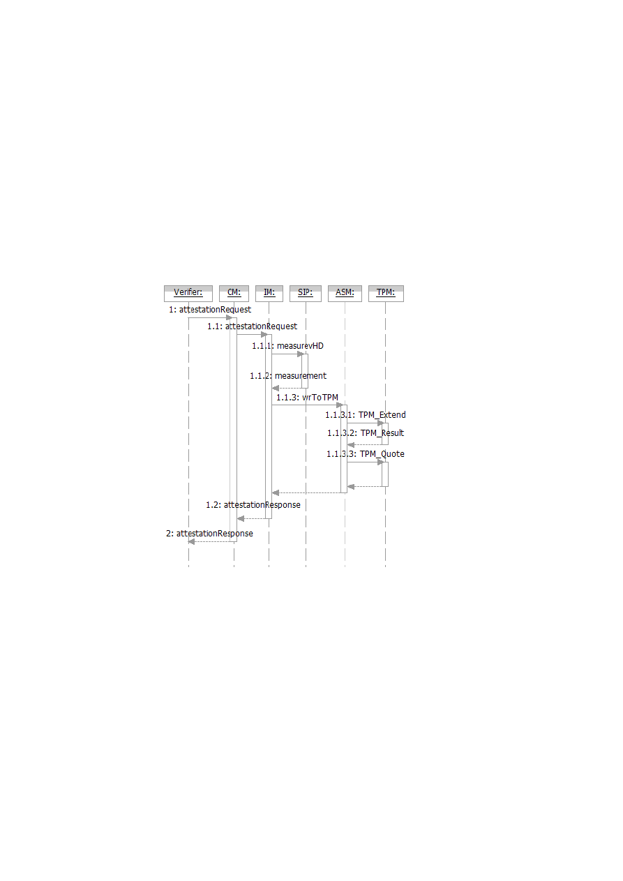
44
OpenTC D05.6 – Final Report of OpenTC Workpackage 5
Figure 5.7: TPM-based attestation on a VM disk
OpenTC Document D05.6/V01 – Final R7628/2009/01/15/OpenTC Public (PU)

CHAPTER 5. POLICY ENFORCEMENT AND COMPLIANCE
45
<attestation-desc>
<attestation type="tpm-based"
challenge="0xaded..."
aik="0xaada3..">
<measurement-desc type="tpm">
<measureTarget name="disk:/dev/sdb1"
dest="PCR16"/>
</measurement-desc>
<attestTarget name="ALLPCRS"/>
</attestation>
</attestation-desc>
Figure 5.8: Attestation descriptor in XML
for its purpose. As described before, projection functions are realized by a set of com-
ponent plug-in modules. Some of these plug-in modules are measurement plug-ins,
which not only return the relevant integrity states of the components but are also the
ones measuring their integrity states in the first place. The attestation descriptor con-
tains one or more measurement descriptors. Based on the measurement descriptors,
the IM knows the exact set of measurement plug-ins to invoke.
Figure 5.8 shows an example attestation descriptor as a XML structure. It contains
an
<attestation>
section, which defines the type of attestation (
tpm-based
)
and the parameters needed for attestation (the TPM Attestation Identity Key or
AIK
and a
challenge
). Nested in the attestation descriptor is a measurement descriptor,
which specifies a measurement target (
measureTarget
) and a destination (
dest
).
The target indicates what is to be measured (in this case, a VM disk image), whereas
the destination indicates where the result should be stored (in this case, the TPM’s PCR
number 16). The
<attestTarget>
defines the scope of the requested attestation (in
this case, all PCRs).
Based on the user credential supplied, the CM checks whether the verifier has the
right to request attestation of the system sub-states indicated by the attestation descrip-
tor. The check is essentially a way of determining whether the requested projection is
a projection that conforms to the access restriction specification; hence, it is useful in
enforcing access restriction. If the check reveals that the verifier wants to have more
attested than what he/she is allowed to, then the entire attestation request is denied.
Otherwise, the CM forwards the request to the IM (step 1.1).
The IM extracts the measurement descriptor(s) from the attestation descriptor and
delegates the measurement(s) to the appropriate plug-in(s). In our example, the IM
invokes the
measurevHD
function at the SIP passing the measurement descriptor as a
parameter (step 1.1.1). The plug-in completes the requested measurement and returns
the measurement result back to the IM (step 1.1.2). Although step 1.1.2 might look like
an unnecessary extra step, the indirection via the IM allows the measurement plug-ins
to be written independent of the TPM or similar future devices that are indicated as
dest
.
The IM invokes the
wrToTPM
function at the ASM with the challenge, the
AIK
,
the measurement result, and the destination PCR (step 1.1.3). The actual writing of the
result into the PCR happens by the
TPM
_
extend
operation (step 1.1.3.1). Thereafter,
a
TPM
_
Quote
gets created and returned to the ASM (steps 1.1.3.2 and 1.1.3.3). The
ASM wraps the
TPM
_
Quote
into an
attestationResponse
and returns it to the IM. The
OpenTC Document D05.6/V01 – Final R7628/2009/01/15/OpenTC Public (PU)
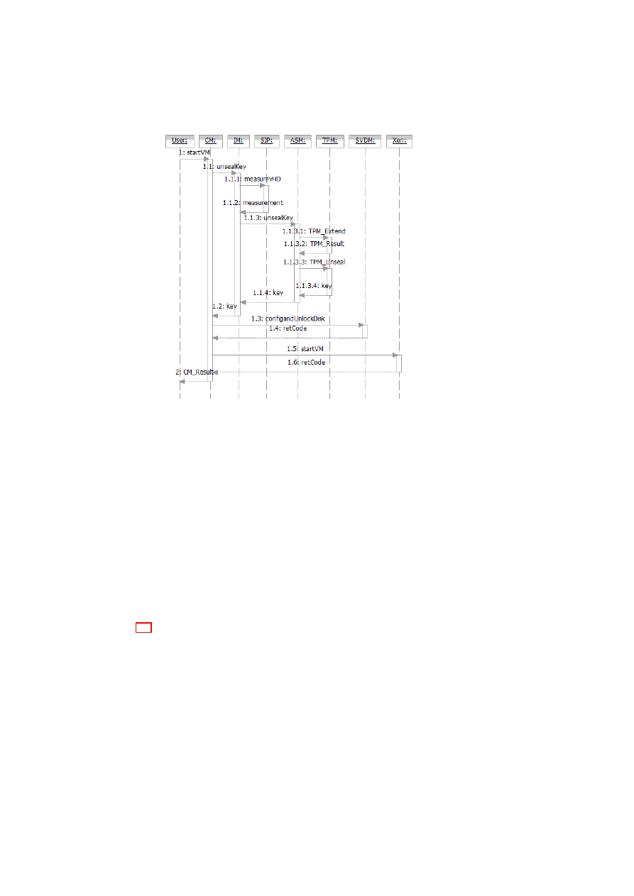
46
OpenTC D05.6 – Final Report of OpenTC Workpackage 5
Figure 5.9: Creation of a VM with TPM-based sealing
attestationResponse
includes not only the
TPM
_
Quote
but also the relevant log files.
The IM returns the
attestationResponse
to the CM (step 1.2), which forwards it to the
verifier (step 2).
A verifier can check the attestation result by recomputing a hash over the attestation
targets (i.e., the relevant log files) specified in the
attestationResponse
and comparing
the resulting hash with the hash in the PCR from the
TPM
_
Quote
.
The PCR in which the measurement result is stored will be reset after the attestation
process has finished. Therefore, our prototype requires a TCG 1.2 compliant TPM, and
the
dest
PCR has to be
16
or higher.
5.5.2
(Re-)Starting a VM with TPM-based Sealing
Figure 5.9 shows the component interactions for (re-)starting a VM with a sealed disk
image. In this use case, we show how to enforce a policy that specifies that the key for
decrypting the disk image be revealed only after measuring the disk image and only if
the measurement value written into a specified PCR matches the value against which
the key was sealed.
The user interacts with the CM through the
startVM
call to (re-)start the VM
(step 1). After determining that the disk image has to be first decrypted through unseal-
ing, the CM obtains the sealing descriptor that was given to it at the time of sealing.
Like the attestation descriptor, the sealing descriptor also contains one or more mea-
surement descriptors, which are used to let the IM know the exact set of measurement
plug-in modules to invoke.
OpenTC Document D05.6/V01 – Final R7628/2009/01/15/OpenTC Public (PU)

CHAPTER 5. POLICY ENFORCEMENT AND COMPLIANCE
47
<sealing-desc>
<sealing type="tpm-based" keyid="0x01">
<measurement-desc type="tpm">
<measureTarget
‘‘
name="file:/xenimages/vm1image"
desc="PCR16"/>
</measurement-desc>
</sealing>
</sealing-desc>
Figure 5.10: Sealing descriptor in XML
Figure 5.10 shows an example sealing descriptor as an XML structure. It contains
an
<sealing>
section, which defines the type of sealing (
tpm-based
) and the pa-
rameters needed for unsealing (the identifier of the key protected by the TPM). Nested
in the sealing descriptor there is a measurement descriptor, which specifies a measure-
ment target (
measureTarget
) and a destination (
dest
). The target indicates what
is to be measured (in this case, a VM disk image), whereas the destination indicates
where the result should be stored (in this case, the TPM’s PCR number 16).
The CM calls the IM interface
unsealKey
(step 1.1), passing the sealing descriptor
as a parameter. The IM extracts the measurement descriptor from the sealing descrip-
tor and calls the
measurevHD
interface of the SIP with the measurement descriptor
(step 1.1.1). The plug-in reads the list of
measureTargets
, and accordingly mea-
sures the disk image. It returns a measurement result list to the IM (step 1.1.2). The
IM calls the ASM, which handles TPM-related functions (step 1.1.3). The ASM writes
the measurements to the TPM by invoking the
TPM
_
Extend
operation (step 1.1.3.1).
Furthermore, the ASM performs the unsealing of the key requested by invoking the
TPM
_
Unseal
operation (step 1.1.3.3). If the
dest
PCR value matches the value at the
time of sealing, then the disk is in the desired state and the unseal operation is success-
ful (step 1.1.3.4); in that case, the ASM returns a key back to the IM (step 1.1.4), which
in turn returns the key to the CM (step 1.2). In case the unseal operation fails, the ASM
would return a failure. The CM calls the SVDM function
configAndUnlock
()
to attach
and unlock the disk (steps 1.3 and 1.4). Upon successful completion of that function,
the CM instructs the Xen hypervisor to actually start the VM (steps 1.5 and 1.6).
For the sake of simplicity, Figure 5.9 does not show details of key handling such as
loading a sealing wrapper key into the TPM.
5.5.3
Enforcement and Compliance Proofs for Information Flow
Control
Consider, for example, the virtual network topology shown in Figure 5.11 with four
virtual network zones. The topology shows the network of a company (which we
shall call the customer company) connected to the Internet via a demilitarized zone
(DMZ). The customer network is also connected to a management network that allows
an outsourcing provider to manage the customer systems. The management network is
not connected to the Internet.
An information flow-control matrix is a simple way of formalizing the system-wide
flow-control objectives [18]. Figure 5.12 shows a sample matrix for the four virtual
OpenTC Document D05.6/V01 – Final R7628/2009/01/15/OpenTC Public (PU)
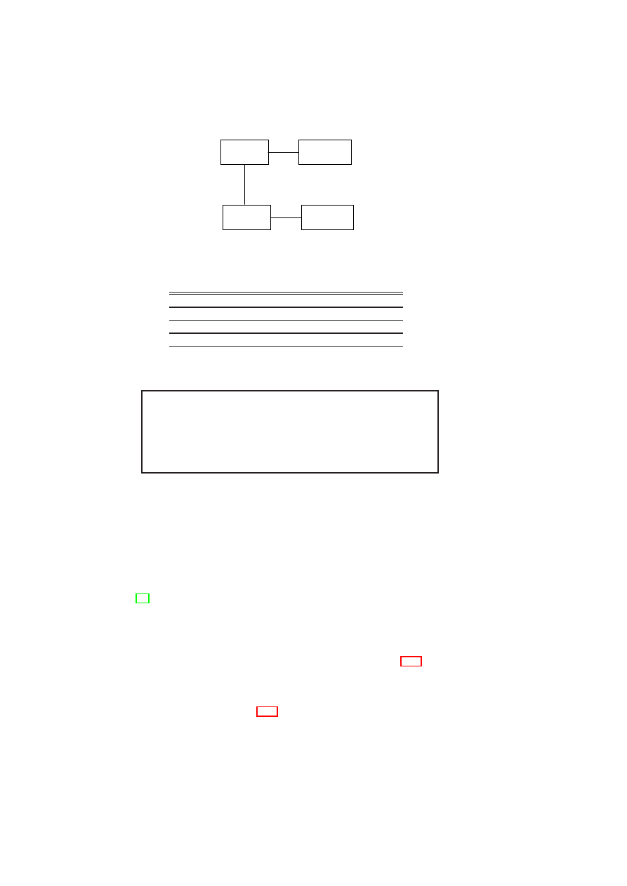
48
OpenTC D05.6 – Final Report of OpenTC Workpackage 5
Customer
Network
Management
Network
DMZ
Internet
Figure 5.11: Virtual network topology
from/to
Cust
.
DMZ
Mgmt
.
Internet
Cust
.
1
1
1
0
DMZ
1
1
0
1
Mgmt
.
1
0
1
0
Internet
0
1
0
0
Figure 5.12: Flow control matrix
<flow-policy>
<zone id="customer-net">
<permit id="mgmt-net" />
<permit id="dmz" />
</zone> ...
</flow-policy>
Figure 5.13: Flow control policy in XML
network zones. Each matrix element represents a policy specifying the information
flows permitted between a pair of network zones. The 1 elements along the matrix
diagonal convey the fact that there is free information flow within each network zone.
The 0 elements in the matrix are used to specify that there should be no information
flow between two zones, e.g., between the management zone and the Internet.
In [18], we described a Xen-based prototype of a secure network virtualization
architecture that is based on the concept of Trusted Virtual Domains. The architecture
allows arbitrary network topologies connecting VMs. For example, different VMs on
the same physical infrastructure may belong to different virtual network zones. Despite
this, the architecture ensures the enforcement of policy-based information flow control.
We can use the architecture for enforcing the policies shown in Figure 5.12.
By combining the Xen prototypes of our PEV architecture and our secure network
virtualization architecture, it is possible to validate the configuration of the virtual net-
working subsystem on each host. The subsystem exports an XML version of its flow-
control matrix, as shown in Figure 5.13. The network measurement plug-in outputs
the XML structure of the flow-control policy, when invoked by the IM. By request-
ing attestation of the TCB and this policy, a verifier can obtain a compliance proof for
the correct configuration of the virtual networking subsystem on a given host. At the
OpenTC Document D05.6/V01 – Final R7628/2009/01/15/OpenTC Public (PU)

CHAPTER 5. POLICY ENFORCEMENT AND COMPLIANCE
49
<xsl:template
match="/flow-policy/zone[@id=’customer-net’]">
<xsl:choose> <xsl:if
test="count(*[@id=’dmz’])=1
and count(*[@id=’mgmt-net’])=1">
<true />
</xsl:if>
</xsl:choose>
</xsl:template>
Figure 5.14: XSLT condition
verifier, a XSLT stylesheet is used to perform further transformations on the XML file
returned by the platform. The XSLT stylesheet is a concrete implementation of the at-
testation predicate
Π
(described in Section 5.2.2), which assesses whether the platform
is trustworthy from the verifier’s point of view. The result of the predicate will serve to
convince the verifier that the policy in Figure 5.12 is the actual flow-control policy as
enforced by the network subsystem. If access restriction is an important concern, the
XML output from the plug-in modules may be first processed by an XSLT stylesheet
that implements a access filter before passing it on to the verifier. In such a case, the
stylesheet would be embedded in the platform TCB.
A user can also protect sensitive information (say, an encryption key) against access
by an untrusted network configuration using a two-stage procedure. The first stage is
sealing, in which the user has to specify the binary configuration of the TCB and condi-
tions for checking whether a given network configuration is a trusted one. Figure 5.14
shows an XSLT script that encodes the condition that the customer network should be
directly connected only to the DMZ and the management network of the outsourcing
provider, but not to any other network. The input to the XSLT script is the XML pol-
icy that is output by the network measurement plug-in. The XSLT script is a concrete
realization of the user-specified predicate
Π
in our formal model (Section 5.2). The
user seals the key to both the state of the TCB and the value of a resettable PCR; the
latter reflects the integrity of the XSLT script and the integrity of the plug-in identifier.
The second stage is unsealing, in which the IM (i) obtains the result of the plug-in, (ii)
applies the result as input to the XSLT script, (iii) extends the resettable PCR with the
hash of the XSLT script and the network measurement plug-in identifier, and (iv) tries
to unseal the actual key. For steps (iii) and (iv), the IM invokes the ASM. The TPM
should only reveal the key if the TCB is correct and the XSLT evaluated to
<true/>
when executed on their output.
5.6
Conclusion
We introduced a formal model for managing the integrity of arbitrary aspects of a
virtualized system and evaluating system compliance with respect to given security
policies. Based on the model, we described an architecture, called PEV, for protecting
security policies against modification, and allowing stakeholders to verify the poli-
cies actually implemented. We generalized the integrity management functions of the
OpenTC Document D05.6/V01 – Final R7628/2009/01/15/OpenTC Public (PU)

50
OpenTC D05.6 – Final Report of OpenTC Workpackage 5
Trusted Platform Module, so that they are applicable not just for software binaries, but
also for checking security compliance and enforcing security policies. We described
a prototype implementation of the architecture based on the Xen hypervisor. We also
presented multiple use cases to demonstrate the policy enforcement and compliance
checking capabilities of our implementation.
OpenTC Document D05.6/V01 – Final R7628/2009/01/15/OpenTC Public (PU)

Chapter 6
Hierarchical Integrity
Management for Complex
Trusted Platforms
Serdar Cabuk, David Plaquin (HP), Theodore Hong, Derek Murray, Eric John
(CUCL)
6.1
Introduction
Trusted Computing has been proposed as a means of providing verifiable trust in a
computing platform. However, as virtualization becomes more popular and platform
changes (such as security patches) occur more frequently, the established model for
Trusted Computing is insufficient to cope in real-world scenarios. We therefore intro-
duce an extensible integrity management framework that is better suited to deal with
complicated trust dependencies and change management.
The goal of Trusted Computing is to enable third parties to remotely attest and
verify the configuration of a computing platform in a secure manner. Existing trusted
platforms typically contain a component that is at least logically protected from sub-
version. The implicitly trusted components of a trusted platform – in particular, the
hardware Trusted Platform Module (TPM) – can be used to store integrity measure-
ments, and subsequently report these to users (or remote entities) with a cryptographic
guarantee of their veracity. Users can then compare the reported measurements with
known or expected values, and thereby infer whether the platform is operating as ex-
pected (e.g., it is running the expected software with the expected configuration while
enforcing the expected policies).
Present implementations of Trusted Computing technology can take immutable
snapshots of a whole platform, which can then be used as proof of trustworthi-
ness [104, 39, 54, 35]. They do not, however, provide more granular verifications of
platform components such as individual virtual machines (VMs) and applications. The
platform is treated as a whole, and while it is possible to store integrity measurements
of VMs and applications, the limited amount of storage in a TPM means that it is not
51
52
OpenTC D05.6 – Final Report of OpenTC Workpackage 5
possible to represent individual components and the dependencies between them. Fur-
thermore, it is not possible to manage changes to measured components. The current
scheme advocated by the Trusted Computing Group (TCG) deems all such changes
to be malicious [114]. This is certainly impractical for modern server environments,
which undergo a constant bombardment of security patches and policy changes. In
2007 alone, Microsoft released 11 security related patches for the Windows operating
system [3], while a typical enterprise anti-virus application will undergo two to five
updates in an average week [80].
In this paper, we introduce an extensible integrity management framework that
addresses these two shortcomings. To improve integrity management, we explicitly
represent integrity dependencies between platform components by giving individual
registers to each component to store their integrity measurements, and chaining these
components together in a dependency graph. To improve change management, we
introduce a new distinction between reversible and irreversible changes to measured
components. A reversible change is one that can be undone and is guaranteed not to
have any permanent effects. The introduction of reversible changes allows the platform
integrity to be modified temporarily, for example when a device is hot-plugged and
then removed. Although the platform may no longer be considered trustworthy during
the time that the change holds, its integrity can be safely restored after the change is
undone.
Our resulting framework gives a better understanding of a platform’s security prop-
erties, which can be used in policy verification. Like existing Trusted Computing im-
plementations, our services can be used to grant access to protected resources (such
as encrypted storage) only when the policy is satisfied; however, unlike existing im-
plementations, these policies can be more fine-grained, dynamic, and flexible. Our
prototype implementation, built on the Xen virtual machine monitor [30], includes
the integrity management framework and a credential manager service, which demon-
strates the use of enhanced policy checks to control access to security credentials.
Chapter Outline
Section 6.2 outlines the motivation and high-level design for our
integrity management framework. Section 6.3 presents the basic framework, which
provides integrity services to individual components; Section 6.4 extends this into re-
versible integrity changes and an explicit dependency graph, and provides use cases
for this model. Section 6.5 presents some examples of security services that could
make use of our framework. Section 6.6 describes our prototype implementation of the
framework and the credential management service on Xen. Finally, in Section 6.7 we
draw some conclusions.
6.2
Design Overview
The typical design for a trusted platform comprises a hardware TPM and software in-
tegrity management services. These services measure platform components, store in-
tegrity measurements as immutable logs and attest these measurements to third parties.
The services use the TPM to provide a link with the CRTM. In a non-virtualized plat-
form, with relatively few components to be measured, this model is sufficient. How-
ever, it does not scale to complex virtualized platforms that have a plethora of com-
ponents and dependencies between these components. In this section, we first discuss
OpenTC Document D05.6/V01 – Final R7628/2009/01/15/OpenTC Public (PU)

CHAPTER 6. HIERARCHICAL INTEGRITY MANAGEMENT
53
the limitations of the existing model. We then present the high-level design goals that
motivate our integrity management framework.
6.2.1
Hardware Limitations
Current integrity management systems typically employ the TPM as the sole repository
for integrity measurements (see Section 4). Unfortunately, such schemes are funda-
mentally limited by the hardware capabilities of a TPM:
1. A TPM contains a small, limited amount of memory (PCRs). The TCG spec-
ification recommends that a TPM has at least 16 PCRs [114]. Therefore, for
portability, we cannot assume that a TPM will have any more than 16 PCRs.
Hence, it is not feasible to store individual measurements for a large number of
virtualized platform components.
2. The limited number of PCRs is typically addressed by aggregating measurements
in the same register. Where two components are independent, this introduces a
false dependency between them. Furthermore, the definition of the
extend
function introduces an artificial dependency on the order in which they are ag-
gregated.
3. It is not possible to reverse the inclusion of a measurement in a TPM register.
Therefore, it is impossible for a platform component to report a change to its
integrity (e.g. by the dynamic loading of some code, or the connection of a new
device) and revert back (after unloading/disconnection).
To illustrate these limitations, consider the following example. A server platform
hosts tens of small VMs, each of which runs a particular service. To keep track of the
platform integrity on a traditional TPM-based system, the measurements must be ag-
gregated, because there are more VMs than PCRs. For example, it might be necessary
to store measurements for a virtual network switch and a virtual storage manager in the
same PCR, which creates a false integrity dependency between these two VMs. If a
malicious change is made to the virtual network switch, and this change is reported to
the appropriate PCR, the integrity of the storage manager also appears to be compro-
mised. The same is true for all other VMs whose measurements are aggregated in that
PCR.
It would be possible to extend the set of PCRs by giving a virtual TPM to each
platform component [13]. However, by allocating independent virtual PCRs to each
component, it is no longer possible to represent real dependencies between compo-
nents
1
. Furthermore, since the virtual TPMs emulate the behavior of a hardware TPM,
it remains impossible to revert changes.
6.2.2
High-level Design
It is clear that software measurement support is required to address the limitations of
hardware capabilities. We refer to the set of software components that comprise the
integrity framework as the software root of trust for measurement (SRTM). These com-
ponents are part of the platform TCB, and should be isolated from other components;
1
Some virtual TPM designs share a fixed number of PCRs between all virtual TPMs and the hardware
TPM, and these could be used to express dependencies. However, the reliance on the hardware TPM leads
to the same limitations as a single-TPM scheme.
OpenTC Document D05.6/V01 – Final R7628/2009/01/15/OpenTC Public (PU)
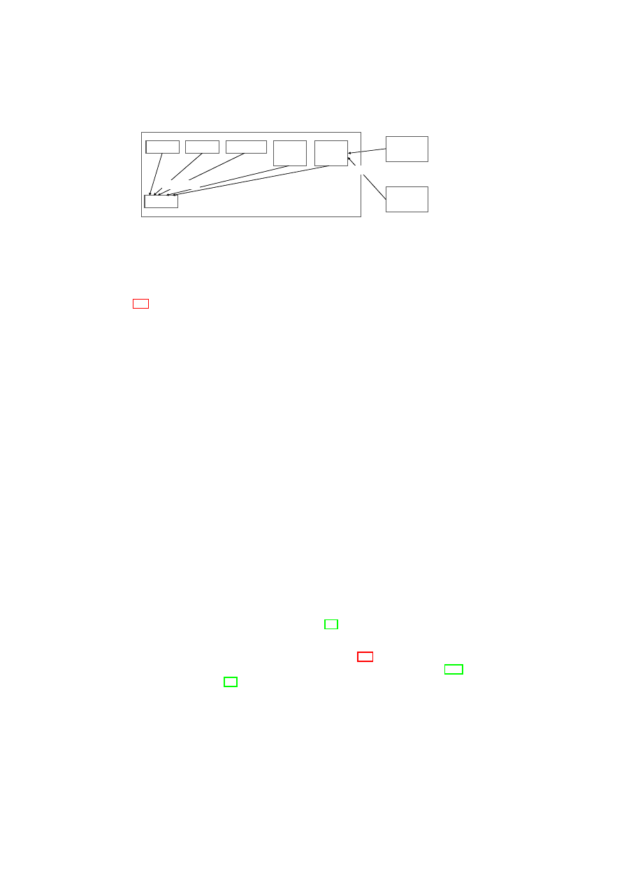
54
OpenTC D05.6 – Final Report of OpenTC Workpackage 5
CRTM
CRTM
BIOS
BIOS
Boot Loader
Boot Loader
OS Kernel
OS Kernel
SRTM
SRTM
TPM
TPM
Dynamic
Component
Dynamic
Component
...
Dynamic
Component
Dynamic
Component
Platform TCB
hashes stored
hashes stored
Figure 6.1: The position of the SRTM within the overall integrity management frame-
work.
for example, by virtualization. Dynamic components outside the platform TCB rely
on the SRTM to store measurements on their behalf, rather than the underlying TPM.
Figure 6.1 illustrates the position of the SRTM within the overall integrity management
framework.
Our framework has the following design objectives:
Unlimited measurement storage The framework should allow the storage of individ-
ual integrity measurements for an arbitrary number of components.
Explicit dependency representation The framework should allow the explicit and
unambiguous representation of an arbitrary number of dependencies between
platform components. There should be no false or artificial dependencies intro-
duced by aggregation.
Static integrity management The framework should provide a superset of the func-
tionality of a traditional TPM, with respect to static integrity.
Dynamic integrity management The framework should enable the integrity state of
a platform component to revert to a previous trusted state in a controlled and
verifiable manner.
Link to hardware TPM The software framework should be linked in a chain of trust
to the hardware TPM. This can be achieved by storing the measurements for the
SRTM and other static components in the platform TCB (such as the hypervisor
and any physical device drivers) in the TPM. As this set of components is small
and non-changing, the limitations of a hardware TPM do not come into effect.
Minimal TCB In order to improve the trustworthiness of the framework, the SRTM
and other components in the TCB should have a minimal amount of code and size
of interface. This paper does not focus on minimizing the TCB, but a possible
approach would involve using disaggregation [83].
Platform independence The framework should not be limited to a single hypervisor
technology. Although the implementation (see Section 6.6) was carried out using
Xen, it should be possible to use alternative technologies, such as VMware [109]
or an L4 microkernel [74].
6.3
Basic Integrity Management
In this section, we present a basic design for the SRTM service that we introduced
earlier. This platform-independent service provides the minimal functionality needed
OpenTC Document D05.6/V01 – Final R7628/2009/01/15/OpenTC Public (PU)
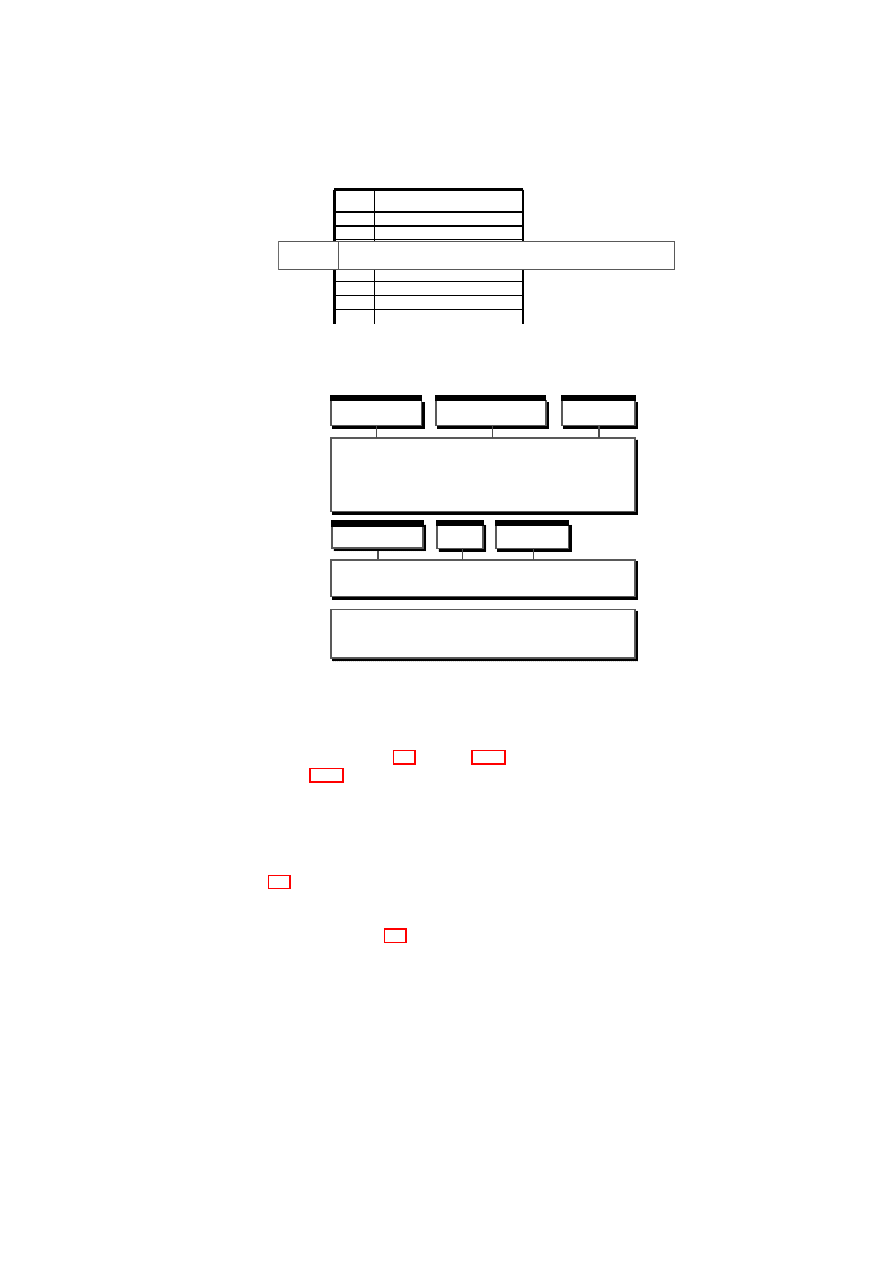
CHAPTER 6. HIERARCHICAL INTEGRITY MANAGEMENT
55
#
CCRs
#
CCRs
CCR03
2f:d2:c1:42:5c:ce:9e:ce:62:50:71:22:db:43:61:25:ab:82:be:55
Figure 6.2: Basic integrity management components – Component configuration reg-
ister table.
VMM and Hardware
BMSI
Management
Protected Storage
Integrity
BIM
...
Management
TPM
Figure 6.3: Basic integrity management components – The BIM architecture.
to manage the integrity of dynamic (non-TCB) platform components, which will be
extended further in Section 6.4. Section 6.3.1 sets out the basic measurement model,
while Section 6.3.2 describes the corresponding service architecture and interfaces.
6.3.1
Measurement Model
The Basic Integrity Management (BIM) service stores static integrity measurements of
dynamic components that are arranged in a flat hierarchy, such as the one shown in
Figure 6.4. Each component has a single Component Configuration Register (CCR)
associated with it. A CCR is analogous to a PCR and holds integrity measurements for
that component. The measurements are held together in a global CCR table similar to
the one depicted in Figure 6.2.
Static Measurements
The BIM measurement model mimics TPM measurement capabilities but stores in-
tegrity measurements in software rather than hardware. Each registered dynamic com-
ponent is assigned a BIM CCR to which its measurements are reported. This is
achieved by an
extend
operation, which stores a new measurement in a CCR by
hashing it together with the current value of the CCR. Dynamic components use this
OpenTC Document D05.6/V01 – Final R7628/2009/01/15/OpenTC Public (PU)

56
OpenTC D05.6 – Final Report of OpenTC Workpackage 5
CID
PID
0
-
1
0
2
0
3
0
CID
PID
0
-
1
0
2
0
3
0
1
22
33
Platform TCB
VM
VM
VM
0
00
11
22
33
Figure 6.4: Simple integrity use case – a flat hierarchy.
operation to report ongoing measurements when their contents change. For example,
a firewall service would extend its CCR if its rule-set was about to be changed. The
specifics of when/how measurements are taken is component-dependent, but the logic
that performs this activity must be trusted to report changes faithfully. This behavior
is assured by the initial measurement of the component by the component that starts it.
In the BIM model, this can only be a static (platform TCB) component.
This measurement model provides better scalability than models that use the TPM
as the sole repository for measurements. By using software registers, the BIM can
store a virtually unlimited number of individual measurements. Hence, no aggregation
is needed. However, the measurements are still accumulated and the CCRs are irre-
versible. That is, recording a measurement
M
1
, followed by a changed measurement
M
2
, followed by
M
1
again, results in a different value than the original recording of
M
1
alone. Hence, components are not allowed to change in any way without perma-
nent loss of integrity. Even if a change is later undone, the component cannot return
to its previous trust state. In Section 6.4, we will address this problem by employing
dynamic registers for reversible measurements.
Simple Trust Dependency
The BIM service implements a flat hierarchy to capture the integrity dependencies
between platform components. In this model, the integrity of dynamic components
solely depends on the integrity of the underlying platform TCB. We show an example
flat hierarchy in Figure 6.4. The components labeled one, two, and three are virtual
machines running directly on the trusted platform. Component zero is the platform
TCB that includes the SRTM (in this case, the BIM service). Each VM depends only
on the platform TCB underneath. If the integrity of the TCB (component zero) is
compromised, then the integrity of all of the VMs is compromised as well. However,
the VMs are independent of one another and therefore do not have a trust dependency.
As an example, if the integrity of VM
1
is compromised, the integrity of VM
2
and VM
3
remains intact.
In what follows, we depict the integrity relationships between components using
a dependency graph, and represent it using a dependency table. Figure 6.4 shows a
simple graph and its dependency table equivalent. For example, the second row in the
dependency table states that the integrity of the child component one (VM
1
) depends
on the integrity of the parent component zero (TCB).
In the simple BIM model, there is always a single trusted component (the plat-
form TCB) on which all other components depend. This yields the “flat hierarchy”
dependency graph and table in Figure 6.4. The flat hierarchy arises, because a dynamic
component (such as a VM) can only be started by a trusted component. Since the TCB
is static and platform-wide, it is not possible for a dynamic component to start – and
hence become a parent of – another dynamic component. Therefore the BIM cannot
OpenTC Document D05.6/V01 – Final R7628/2009/01/15/OpenTC Public (PU)

CHAPTER 6. HIERARCHICAL INTEGRITY MANAGEMENT
57
Integrity
Description
extend
Takes a hash value as an argument and irreversibly extends the com-
ponent CCR with that hash.
quote
Takes arbitrary external data (i.e., nonce) and returns a quotation of
the current TCB measurements, the nonce, and the component CCR
value signed by a TPM attestation identity key (AIK).
Protected Stor-
age
Description
seal
Takes data to be protected, seals it to the TPM binding it to current
TCB and CCR measurements, and returns the sealed (encrypted) blob.
unseal
Takes the sealed blob and unseals and returns the data iff the integrity
of the TCB and the component are verified as intact.
Management
Description
register
Takes the initial measurement, adds the component to the dependency
table, and fills the CCR with the initial measurement.
delete
Deletes the component and all its sealed data.
Table 6.1: BIM integrity, protected storage, and management interfaces.
manage, for example, the integrity of an application started within a VM. However, the
BIM serves as a basis to build the hierarchical model which addresses this limitation,
which is introduced in Section 6.4.
6.3.2
The BIM Architecture
As shown in Figure 6.3, BIM services are grouped under three interfaces:
Integrity interface This interface provides functions to report and quote integrity
measurements of dynamic (i.e., non-TCB) components. Components use this
interface to extend their register values when they detect significant changes to
their measured content. A component is only allowed to alter its own register,
while an integrity quote can be requested by any entity. Using the underlying
TPM interface, the latter operation returns a signed integrity digest that contains
the measurements of the dynamic component and the platform TCB. Using this
digest, a third party can verify the complete integrity chain.
Protected storage interface This interface provides functions to store and reveal se-
crets on behalf of dynamic components. These secrets are bound to the integrity
of the TCB and the owner component, i.e., they are revealed if and only if the
integrity of the component and its ancestors (in the BIM case, the platform TCB)
is intact. The BIM uses the underlying TPM interface for sealing and unsealing
data to and from the TPM, which automatically implies a verification check on
the TCB. Verification of the component’s integrity can be done either by the BIM
or delegated to a third-party verifier. Our prototype implements the former case
in which the BIM needs to store the expected measurements for comparison. We
use the TPM sealing operation itself to do so and use the CCR values at the time
of sealing as the future expected values. We concatenate these values to the se-
cret and seal the whole blob. The unsealing operation at a later time returns not
only the sealed secret but also the expected set of measurements that we compare
to the CCR values at that time.
OpenTC Document D05.6/V01 – Final R7628/2009/01/15/OpenTC Public (PU)

58
OpenTC D05.6 – Final Report of OpenTC Workpackage 5
Management interface This interface provides functions to register dynamic compo-
nents to the framework so that their integrity can be tracked by the BIM. The BIM
is a passive service, and so only registered components are tracked. As discussed
in the previous sections, the initial measurement of the component is provided
from outside by a trusted component that measures and initiates the component.
The interface also allows the deletion of components and their sealed data.
Table 6.1 details the individual functions provided by each interface. As shown in
Figure 6.3, the BIM, in turn, makes use of the Basic Management and Security Interface
(BMSI), which provides a platform-agnostic interface to the underlying hypervisor and
hardware TPM. In particular, the BMSI provides functions that enable the BIM to
access the TPM and establish a link to the hardware root of trust. The implementation
of the BMSI is discussed in more detail in Section 6.6.
6.4
Hierarchical Integrity Management
In this section, we present an enhanced design for the SRTM service that we introduced
in Section 6.2. This platform-independent service features dynamic measurements and
a component hierarchy that we use to manage the integrity of dynamic (non-TCB) plat-
form components more effectively. We describe the security model for measurements
in Section 6.4.1. We describe the service architecture and interfaces in Section 6.4.2.
6.4.1
Measurement Model
The Hierarchical Integrity Management (HIM) service stores integrity measurements
in a CCR table as illustrated in Figure 6.2. To overcome the shortcomings of the BIM
model (e.g., irreversible measurements), we have extended it by introducing two new
concepts: dynamic measurements and hierarchical trust.
Dynamic Measurements
The HIM measurement model enhances the BIM model in two ways. First, HIM allows
multiple registers to be assigned to a single dynamic component. This way, component
measurements can be tracked with better granularity. Second, HIM supports dynamic
measurements that can be reported to a resettable register. This increases flexibility
and allows a component to revert back to a trustworthy configuration if permitted by
its change policy.
Change types. We distinguish two types of component changes. More specifically:
An irreversible change is one that requires the component to be restarted before its
integrity can be re-established. Such a change is one made to the integrity-critical part
of the component; that is, to the code or other data of the component that has a potential
impact on the future ability of the component to implement its intended functionality
correctly. An example of an irreversible change is a kernel loading an untrusted device
driver as the driver may make a change to kernel memory that will persist even after it
is unloaded.
A reversible change is one in which the component is permitted to re-establish
integrity without being completely reinitialized. Such a change is one made to a non-
critical part of the component; that is, to code or other data of the component that has
no direct or potential impact on the component’s future security. A component still
OpenTC Document D05.6/V01 – Final R7628/2009/01/15/OpenTC Public (PU)
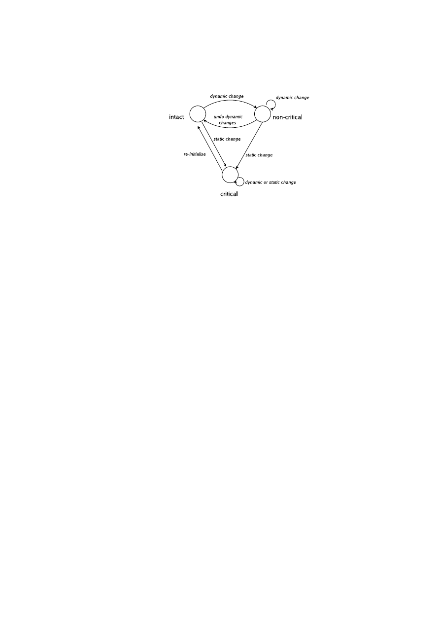
CHAPTER 6. HIERARCHICAL INTEGRITY MANAGEMENT
59
Figure 6.5: Transition diagram for component integrity states. A component in the
non-critical state can be made intact by undoing dynamic changes, but the critical state
can only return to the intact state by re-initialization.
loses its integrity if a change is made to it. However, depending on the exact nature
of the change, we may permit the component to regain integrity (and therefore trust)
by undoing the change and returning to its previous state. For example, changes to
configuration parameters are often reversible – e.g. changing the identity certificate
that a component uses. The integrity management system will need to note such a
change in order to fully report the state of the platform, but the certificate may be
safely changed back without causing security implications. Another example might be
loading a trusted kernel module that is known not to leave any side effects after being
unloaded.
The categorization of a change as reversible or irreversible is component-dependent
and will be set by each component’s own change-type policy. For example, a policy
stating that all changes are irreversible reduces to the static measurement model. A
component that permits reversible changes is referred to as a dynamic component (“dy-
namic” because its integrity state may change multiple times).
Measurement reporting. Recording dynamic measurements requires two mea-
surement registers, a static register and a dynamic register, rather than the single reg-
ister used in the static measurement model. Irreversible changes are reported to the
static register in the same way as in the static measurement model; that is, the
extend
operation is used to combine the new measurement with the existing register value to
obtain the new register value.
extend
(
R, M
) =
hash
(
R
||
M
)
where
R
is the value of the register and
M
is the measurement.
By contrast, reversible changes are reported to the dynamic register by replacing
the previous value held in that register, using the
reset
operation.
reset
(
R, M
) =
M
We can see that attempting to reverse an irreversible change does not return the
static register to its initial state:
R
f inal
=
extend
(
extend
(
R
initial
, M
2
)
, M
1
) =
hash
(
hash
(
R
initial
||
M
2
)
||
M
1
)
6
=
R
initial
OpenTC Document D05.6/V01 – Final R7628/2009/01/15/OpenTC Public (PU)

60
OpenTC D05.6 – Final Report of OpenTC Workpackage 5
However, reversing a reversible change does return the dynamic register to its initial
state:
R
f inal
=
reset
(
reset
(
R
initial
, M
2
)
, M
1
) =
reset
(
M
2
, M
1
) =
M
1
=
R
initial
The exact nature of the reporting activity and the corresponding change-type policy
is component-dependent. However, the logic that performs this activity must be a part
of the initial measurements so that we can trust the component to report the changes to
the correct register.
Integrity states. Depending on the measurement values stored in its static and
dynamic registers, a dynamic component can be in one of three local integrity states:
intact, non-critical, and critical. The component is in the intact state if and only if the
values in the static and dynamic registers are consistent with the expected measurement
values. The component is in the non-critical state if and only if the value in the static
register is consistent with the expected measurement value but the value in the dynamic
register is not. In all other cases, the component is in the critical state. As shown in
Figure 6.5, the foregoing arrangement enables a dynamic component that has only been
subject to non-critical changes to be restored to the intact state. A component that is
in the critical state cannot be restored to any other state unless re-initiated with an
expected configuration (during which both registers are reset).
Security states. Depending on the integrity state, a component can be in three
security states: trustworthy, secure, and insecure. A component is trustworthy if and
only if it is in intact state. A component is secure if and only if it is in intact or non-
critical states. In all other cases, the component is deemed insecure.
Example use case for dynamic registers. Digital Rights Management (DRM) ser-
vices control the distribution of media content onto computing platforms. It is possible
that a DRM service will not push video content to a computing accessory if, for ex-
ample, an external recording device is plugged to it. In this case, software that detects
and installs the plug-and-play drivers for the recording device must be part of the static
measurements. However, the state in which a recording device is detected in the sys-
tem can be reported dynamically. In fact, this can be reflected in the dynamic register
for a secure DRM player application. As long as the recording device is connected,
no content is downloaded. Once the user unplugs the device, the dynamic register is
reset and content can be pushed to the player without requiring the application to be
restarted.
Hierarchical Trust Dependency
We enhance the BIM dependency model by introducing a hierarchy of trust dependen-
cies that we represent as a directed acyclic graph. In such a graph, the edges indicate
trust dependencies where the integrity of the component at the origin depends on the
integrity of the component at the destination. If the integrity of the destination com-
ponent is compromised, then the integrity of the origin component is always compro-
mised as well. However, the reverse is not true. To illustrate these more complex trust
relationships, consider the following use cases.
In Figure 6.4, we see the simple flat hierarchy as previously described in Sec-
tion 6.3. The components labeled one, two, and three are virtual machines running
directly on the trusted platform. Component zero is the platform TCB that includes the
SRTM (in this case, the HIM service). Each VM depends only on the platform TCB
OpenTC Document D05.6/V01 – Final R7628/2009/01/15/OpenTC Public (PU)
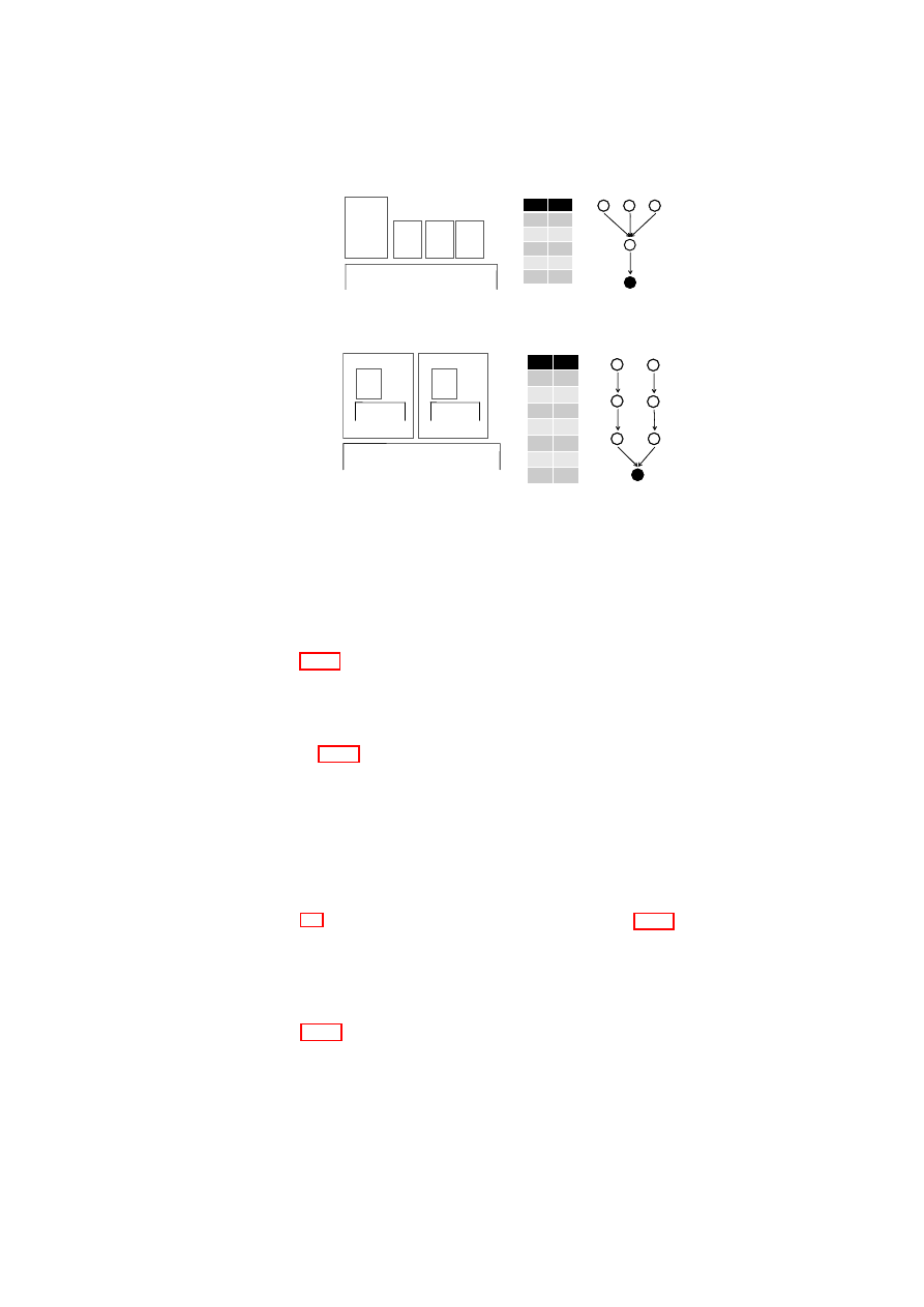
CHAPTER 6. HIERARCHICAL INTEGRITY MANAGEMENT
61
CID
PID
0
-
1
0
2
1
3
1
4
1
CID
PID
0
-
1
0
2
1
3
1
4
1
1
22
Platform TCB
VM
Manager
VM
0
33
VM
44
VM
1
22
33
44
00
(a) Multi-level dependency.
CID
PID
0
-
1
0
2
0
3
1
4
3
5
2
6
5
CID
PID
0
-
1
0
2
0
3
1
4
3
5
2
6
5
1
Platform TCB
VM
0
00
33
33
44
APP
JVM
11
22
44
55
66
2
VM
55
66
VM
VMWARE
(b) Nested components.
Figure 6.6: Hierarchical integrity use cases.
underneath. If the integrity of the TCB (component zero) is compromised, then the
integrity of all of the VMs is compromised as well. However, the VMs are independent
of one another and therefore do not have a trust dependency. As an example, if the
integrity of VM
1
is compromised, the integrity of VM
2
and VM
3
remains intact.
Figure 6.6(a) shows a more complex multi-level dependency. Component one is a
service that manages the life-cycle of components two, three, and four. All components
are virtual machines. The latter VMs are independent of one another, as before, but
their integrity depends on that of the domain manager, whose integrity in turn depends
on the TCB.
In Figure 6.6(b), we see a nested dependency relationship. Components one and
two are virtual machines, which themselves contain further virtual machines: compo-
nent three, which is a Java virtual machine, and component five, which is a VMware
hypervisor. These nested virtual machines support guest components: component four,
a Java application, and component six, a VMware guest. Within component one, a tra-
ditional linear chain-of-trust applies: Java application depends on Java virtual machine
depends on operating system. A similar chain can be found within the VMware com-
ponent. However, these two chains of trust are independent of one another, and both
depend ultimately on the underlying platform TCB.
Figure 6.7 illustrates more complicated use cases. In Figure 6.7(a), we see a mul-
tiple dependency relationship. Component five is a virtual machine that uses services
from components one, two, and four. These components are small virtual machines
that provide virtual networking, virtual storage, and virtual TPM services, respectively.
Further, the integrity of the virtual TPM depends on the integrity of the virtual TPM
manager domain (component three).
Figure 6.7(b) shows a similar VM grouping example which we intend to explore
further in future work. In this example, we use miniature virtual TPM services to assist
and enhance the integrity measurement capabilities of the framework. In this design we
bind a single virtual TPM to a component (application or VM) and delegate component
measurements to this virtual TPM. The virtual TPM then replaces the component CCRs
OpenTC Document D05.6/V01 – Final R7628/2009/01/15/OpenTC Public (PU)
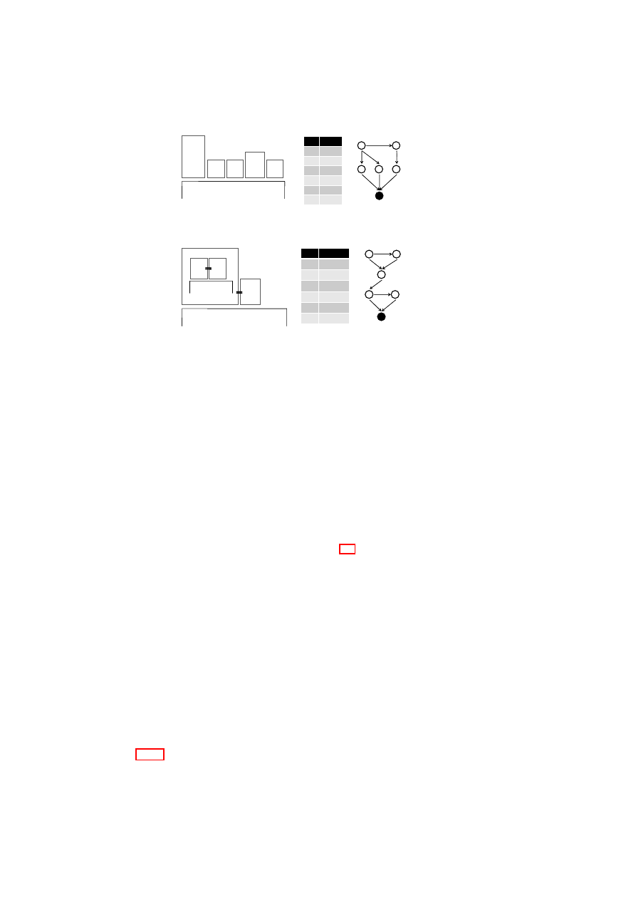
62
OpenTC D05.6 – Final Report of OpenTC Workpackage 5
CID
PID
0
-
1
0
2
0
3
0
4
3
5
{1,2,4}
CID
PID
0
-
1
0
2
0
3
0
4
3
5
{1,2,4}
5
11
Platform TCB
VM vNET
0
22
vSTO
33
vTPM
MGR
44
vTPM
00
11
22
33
44
55
2
(a) Disaggregated services.
2
Platform TCB
VM
0
33
55
APP
JVM
4
vTPM
11
vTPM
CID
PID
0
-
1
0
2
{0,1,M(1)}
3
2
4
3
5
{0,4,M(4)}
CID
PID
0
-
1
0
2
{0,1,M(1)}
3
2
4
3
5
{0,4,M(4)}
00
22
11
55
44
33
3
(b) Virtual TPM binding.
Figure 6.7: More complicated use cases. Dashed lines denote implicit dependency.
to provide more granular run-time measurements for the component it is attached to.
The measurements for the virtual TPM service itself is still held by its own CCRs. As
an example, the integrity of component two now depends on the integrity of component
one (its attached virtual TPM) and the run-time measurements taken by this virtual
TPM (e.g., during authenticated VM
2
bootstrap). We refer to this measurement set as
M(one). The same holds for the application component five and its attached virtual
TPM service component four. The present HIM implementation does not yet support
virtual TPM attachment.
6.4.2
The HIM Architecture
The HIM service implements the same integrity, protected storage, and management
interfaces as the BIM service as presented in Section 6.3, but with the following en-
hancements.
The HIM integrity interface provides an
extend
function that alters the value of
the static CCR in the same way as the BIM equivalent. To support dynamic mea-
surements, the interface also provides a
reset
function that is used to report to the
dynamic register and overwrite its value. In addition, to support hierarchical integrity
dependency, the
quote
function is modified. This function now returns the aggre-
gated integrity measurements of the component in question. Specifically, the signed
quote now contains the TCB integrity measurements plus the measurements of the
component and all its ancestors hashed in a single value.
In the HIM protected storage interface, the
seal
and
unseal
functions are en-
hanced to support component dependency and dynamic measurements. The
seal
function now binds the stored secret to the integrity of all the trust chains that reach
the component in question from the TCB; that is, the subgraph of all paths from that
component to the root TCB. Hence the integrity state of components not on a path be-
tween that component and the TCB is ignored. For example, in the nested use case in
Figure 6.6(b), an integrity compromise in the VMware compartment will not affect the
ability of the Java application to unseal previously sealed information, as long as the
OpenTC Document D05.6/V01 – Final R7628/2009/01/15/OpenTC Public (PU)

CHAPTER 6. HIERARCHICAL INTEGRITY MANAGEMENT
63
Java compartment remains intact.
Lastly, the HIM management interface provides
register
and
delete
func-
tions. The
delete
function is the same as in the BIM. However, the
register
function now takes a dependency list as a parameter that specifies additional ancestor
components the component depends on besides the one that registers the component.
6.5
Policy Verification for Security Services
In this section, we introduce example security services that leverage the HIM frame-
work for policy verification and access control. Our examples include a credential
management service (Section 6.5.1), a virtual TPM service (Section 6.5.2), and a vir-
tual network service (Section 6.5.3).
6.5.1
Credential Management Service
Protected storage services provide secure access to secrets that are sealed to the under-
lying TPM on behalf of their owners. It is expected that these services retain control
over these secrets and enforce the associated access control policies at all times. By
contrast, most storage services such as [104] and the HIM provide one-time verifica-
tion, and are therefore susceptible to a time-of-check to time-of-use vulnerability. This
occurs because these services release the stored secret to the requesting component
once they verify the necessary policies (e.g., HIM unseal successfully verifies the ag-
gregate integrity). Once the secret is revealed, these services can no longer restrict
access to it if the component undergoes a malicious change.
To enable ongoing policy verification and enforcement, we designed and imple-
mented a credential management service (CMS) that uses the integrity management
framework to provide secure access to secrets while maintaining control at all times.
Unlike the HIM unseal operation, CMS credentials are never revealed to requesting
services directly but are always held securely by the CMS. In essence, the CMS is a
reference monitor that mediates and provides access to secured data through a well-
defined interface.
The CMS interface is comprised of management and service interfaces. Compo-
nents use the management interface to register component credentials with the CMS.
To do so, the
register
function takes the credential as input and seals it to the
underlying TPM. The interface also provides a
discard
function which deletes the
stored credential. The service interface provides access to the credentials through a
generic
access
function. We have designed this interface as an extensible plug-in
interface; that is, the exact nature of the interface depends on the nature of the stored
credential and the type of functionality needed. For example, if the stored credentials
are cryptographic keys, we offer a plug-in service that provides encryption/decryption
capabilities so that components can use the interface to encrypt/decrypt data without
seeing the actual key. Regardless of the functionality provided, the CMS uses the HIM
to verify the aggregate integrity prior to each access to the secret.
6.5.2
Virtual TPM Service
A natural extension to the CMS functionality would be to provide a miniature TPM in-
terface to the various platform components, as illustrated in Figure 6.7(b). This enables
these components to have a standardized interface as in [114] to prove their integrity
OpenTC Document D05.6/V01 – Final R7628/2009/01/15/OpenTC Public (PU)

64
OpenTC D05.6 – Final Report of OpenTC Workpackage 5
and provides a strong identity for each component. Such an approach has already been
taken through TPM virtualization [13] which gives each VM a TPM interface imple-
mented by a virtual TPM service. However, it is not yet clear what the best mechanism
is for establishing a secure binding between a virtual TPM and its platform TCB.
Our framework could be used to bridge the gap between virtual TPM services and
the platform TCB. For example, a central trusted CMS service could be used as the
single secure repository for virtual TPM keys. Access to these keys would require
verification of the complete HIM integrity chain, including verification of the platform
TCB. For example, to sign a quote request, a virtual TPM would use the CMS interface
to gain access to its signing key.
6.5.3
Virtual Network Service
Virtualization provides direct isolation of computing resources such as memory and
CPU between guest operating systems on a physical platform. However, the network
remains a shared resource as all traffic from guests will eventually end up on the same
physical medium. Various mechanisms can be used to provide network isolation be-
tween network domains, as described in [19]. In general, encryption must be used for
isolation when network traffic is delivered over an untrusted shared physical medium.
Using our framework in combination with the CMS, one could design a virtual
network (vNET) service which provides isolation through an encryption layer such as
IPSEC. In this setting, the vNET service would store its credentials (e.g., network en-
cryption key) in the CMS, in combination with the expected CCR values of the service
and any ancestor service it depends on (including any potential network configuration
information). Because the key is held by the CMS and not revealed to the vNET ser-
vice, any change in the integrity of the service or its ancestor components would result
in the network link becoming unavailable for the VM connected to this specific vNET.
As a result, the capability of a VM to communicate with its peer within a considered
domain would implicitly prove its trustworthiness, which would provide continuous
authentication as opposed to relying only on an initial handshake as most network au-
thentication mechanisms do.
6.6
Implementation in Xen
In this section, we describe a prototype implementation of the integrity management
framework and the credential management service on the Xen virtual machine moni-
tor [30]. The implementation features the management and service interfaces of both.
Note that although we present our implementation with Xen, the framework could
equally be implemented on an alternative virtualized or microkernel-based platform
(e.g., the L4/Fiasco [70] microkernel).
6.6.1
Infrastructure Overview
The various components of the integrity management framework are provided by one
or more virtual machines, running on top of the Xen virtual machine monitor. The
use of virtualization isolates the trusted platform from a misbehaving guest operating
system, and all communication with the trusted platform passes through well-defined
interfaces. Our implementation is based on Xen version 3.0.4, a VMM for the IA32
OpenTC Document D05.6/V01 – Final R7628/2009/01/15/OpenTC Public (PU)
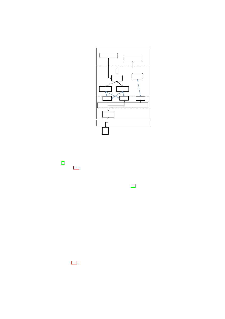
CHAPTER 6. HIERARCHICAL INTEGRITY MANAGEMENT
65
BMSI
libI
libM
libT
BIM
HIM
CMS
vNET Service
vTPM Service
Xen VMM
TPM
TPM
TPM
driver
Se
curi
ty
se
rv
ice
s
Core
se
rvic
es
Library laye
r
Drive
r
laye
r
Dom 0
DMS
Figure 6.8: Illustration of the prototype in a layered stack.
platform, with the VMs running a paravirtualized version of Linux 2.6.18. For inter-
domain communication, we employ the light-weight communication library introduced
in [8].
Figure 6.8 illustrates our implementation on Xen. In the present prototype, all
framework components and the CMS are implemented as libraries and services run-
ning in the Xen privileged management domain Dom0. However, as we have defined
interfaces between each of the components, it should be straightforward to move to-
wards a disaggregated approach as described in [83]. The framework components are
arranged in a layered stack. At the lowest layer is the basic management and secu-
rity interface (BMSI) that provides libraries for domain life-cycle management (libM),
basic TPM access (libT), and integrity management (libI). At the core services layer
are the integrity manager services BIM and HIM that provide basic and hierarchical
integrity management, respectively. Also in this layer are the CMS and the domain
management service (DMS). At the highest layer are the security services that use the
framework for various purposes. The platform TCB consists of the static components
up to and including the SRTM (the BMSI libraries and the integrity managers). How-
ever, for simplicity, we also include the CMS in the platform TCB. The measurements
of these components are reported to the underlying TPM. The application TCB consists
of the platform TCB plus the security services that run on top of it. The measurements
of the latter are reported to the SRTM.
6.6.2
Component Design
In the present prototype, we have implemented the highlighted components depicted
in Figure 6.8, namely the BMSI libraries, BIM and HIM services, CMS, and DMS. In
this section, we present the details of these components including both the BIM and
HIM; however, due to space constraints, we present an example use case that uses only
OpenTC Document D05.6/V01 – Final R7628/2009/01/15/OpenTC Public (PU)

66
OpenTC D05.6 – Final Report of OpenTC Workpackage 5
the HIM.
BMSI Libraries
The Basic Management and Security Interface (BMSI) provides a common and ex-
tensible interface to the underlying hypervisor (i.e., Xen) and the TPM. The BMSI
provides libraries for domain life-cycle management (libM), basic TPM access (libT),
and integrity management (libI).
libM This library provides hypervisor-agnostic management functions to upper layers.
At its lowest level, the library manages allocatable resources called Protection
Domains (PDs). A PD is an executable component that receives an allocation of
memory and CPU cycles, and is scheduled by the hypervisor. On Xen platforms,
a PD is equivalent to a Xen domain (virtual machine). In this prototype, we
use libM to implement the Domain Management Service (DMS). This service
manages the life-cycle of PDs and uses the integrity managers to keep track of
PD integrity. We refer the reader to [83] for further details on the libM and DMS
implementation.
libT This library provides the minimal functionality to access the integrity and pro-
tected storage interfaces of the TPM. Security services (e.g., BIM and HIM)
use this library to obtain a signed quotation of the TCB measurements and
to seal/unseal data to/from the TPM. To do so, libT uses the TPM functions
TPM_Quote()
,
TPM_Seal()
, and
TPM_Unseal()
as described by the
TPM specification [114].
libI This library stores and provides access to the integrity measurement and depen-
dency tables. The
getMeasurement()
function returns a measurement list
that includes the integrity measurements of the component and its ancestors.
In the BIM case, a single value is returned. The
setMeasurement()
func-
tion extends the value of the component register. The
resetMeasurement()
function overwrites the value of the dynamic register. The
addComponent()
function adds an entry to the dependency table and sets its dependencies as spec-
ified. It also adds an entry to the measurements table and records the initial
measurements. The
deleteComponent()
function checks that the specified
component has no successors and removes it from the table.
Component Interactions
The BIM and HIM services implement the interfaces presented in Sections 6.3 and 6.4,
respectively. Similarly, the CMS service implements the interfaces presented in Sec-
tion 6.5.1 and uses a cryptographic service as a plug-in for block encryption and de-
cryption. On a Xen platform, we use these services to manage the integrity of VMs
and applications running on these VMs.
VM integrity management is incorporated into VM life-cycle management. To as-
sist both, the DMS uses the BMSI library libM and the HIM service. The VM start-up
phase in Figure 6.9 depicts the interaction among these components. During this phase,
the DMS invokes libM, which prepares resources for the VM, measures the VM image
(comprising the kernel, an optional initial ramdisk and command-line parameters), and
stores the measurement in the CCR for that VM. This performs a function similar to a
secure bootloader, and it is the responsibility of the kernel to measure any components
OpenTC Document D05.6/V01 – Final R7628/2009/01/15/OpenTC Public (PU)
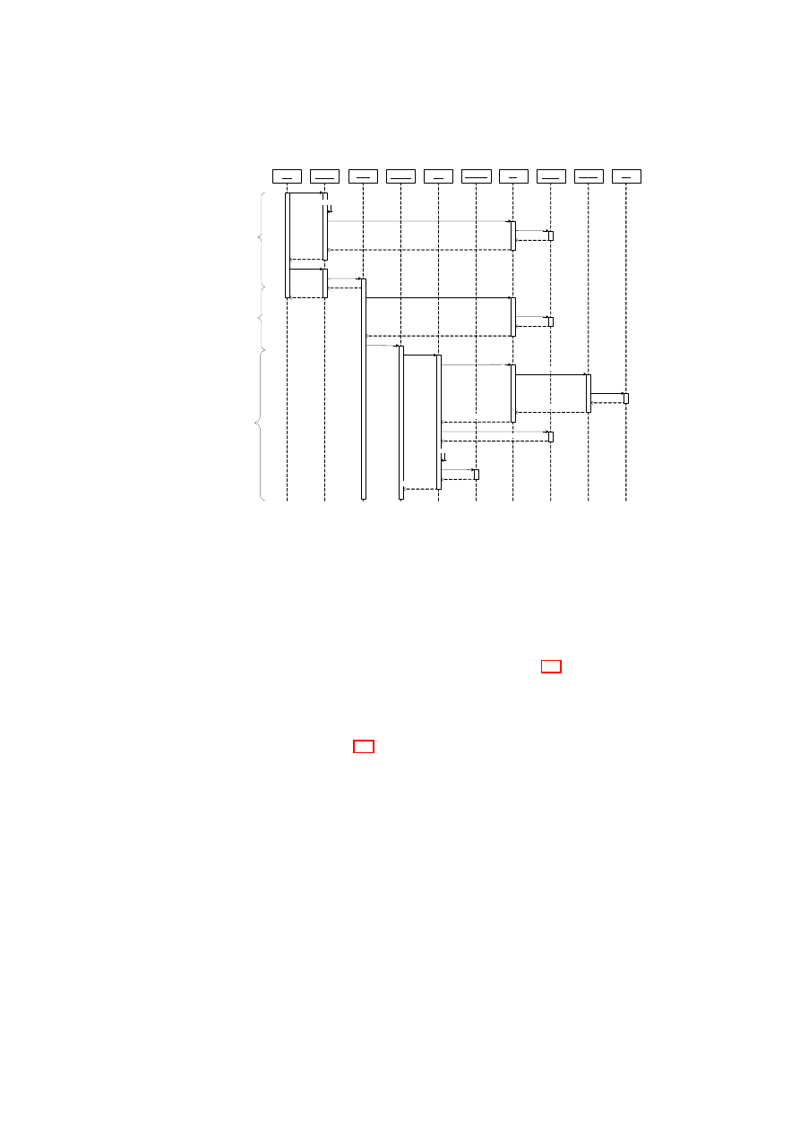
CHAPTER 6. HIERARCHICAL INTEGRITY MANAGEMENT
67
DMS
BMSI:libM
prepareVM()
runVM()
VM_STARTED
PD:VM
preparePD()
HIM
register()
CID
BMSI:libI
addComponent()
CID
startPD()
PD_STARTED
BMSI:libT
unseal()
TPM
TPM_unseal()
unsealed_blob
getMeasurements()
componentMeasurements
VM:DRMS
register()
CID
DRMS.run()
unseal()
addComponent()
CID
VM_READY
CMS
CMS:Crypto
access()
decryptedContent
unsealed_blob
unsealed_blob
verify()
decrypt()
decrypted_blob
Figure 6.9: Sequence diagram of interactions between the framework services for a
DRM application use case.
which it subsequently loads. The DMS also registers the new VM with the HIM ser-
vice, and configures any dependencies between the new VM and existing VMs. The
HIM uses libI to store this information in the measurement and dependency tables.
Following the successful completion of the above steps, the DMS starts the VM.
The HIM service additionally allows applications running in VMs to be registered
with the framework. The application start-up phase in Figure 6.9 depicts the case in
which the VM that was started in the previous phase loads and registers a DRM service
with the HIM. In this case, the VM becomes an ancestor of the service and provides its
initial measurements. As a result, the cumulative integrity of the service now includes
the VM’s measurements as well as the platform TCB measurements.
The last phase in Figure 6.9 depicts a use case in which the DRM service that was
started in the previous phase attempts to decrypt encrypted media content using a key
that is stored on the TPM on behalf of this service. The DRM service invokes the CMS
service interface to request access to this key. The CMS then invokes HIM unseal to re-
trieve the key from the TPM. HIM unseals the key if and only if the underlying policies
regarding the key’s release are satisfied. In this case, the key is unsealed from the TPM
and returned to the CMS if the integrity of the platform TCB is intact. On receiving the
key from the HIM, the CMS performs further verification. It compares the expected
CCR values of the DRM service and its ancestor VM (unsealed along with the key) to
the current CCR values. If the measurements match, the CMS uses its cryptographic
service to decrypt the block, which is then returned to the DRM service. Note that any
subsequent access requests to the key will also follow a similar verification cycle, with
the exception that HIM (hence TPM) seal is omitted because the CMS caches the key
internally.
OpenTC Document D05.6/V01 – Final R7628/2009/01/15/OpenTC Public (PU)

68
OpenTC D05.6 – Final Report of OpenTC Workpackage 5
6.7
Conclusions
In this paper, we have introduced a novel integrity management framework that im-
proves on the integrity measurement and policy verification capabilities of present
Trusted Computing solutions. In particular, our framework is able to cope with the
proliferation of measured components and dependencies between them as well as dy-
namic changes to platform components. In essence, the framework implements a small,
software-based root of trust for measurement (SRTM) that provides a secure link to the
core root of trust for measurement (CRTM). We have implemented our framework on
the Xen virtual machine monitor and proposed several ways in which security services
could take advantage of this architecture for policy verification and access control.
We anticipate integrity and trust management to become especially useful for appli-
cation and service level components. We will therefore continue to investigate further
potential uses for our framework by user level applications. In the short term, we plan
to implement CMS-aware services such as a virtual network service based on [19] that
uses the CMS to store encryption keys. The virtual TPM service is also particularly
interesting. In the long term, we plan to investigate various ways of exploiting our
framework to help enhance the security properties of virtual TPM services (e.g., their
binding to the platform TCB). Conversely, we plan to use virtual TPM services to help
enhance the measurement capabilities of the HIM framework and provide more granu-
lar run-time measurements compared to a single CCR.
OpenTC Document D05.6/V01 – Final R7628/2009/01/15/OpenTC Public (PU)

Chapter 7
Towards Automated
Provisioning of Secure
Virtualized Networks
S. Cabuk, C. Dalton (HPL), H. Ramasamy, M. Schunter (IBM)
7.1
Introduction
Virtualization allows the abstraction of the real hardware configuration of a computer
system. A computer uses a layer of software, called the Virtual Machine Monitor
(VMM), to provide the illusion of real hardware for multiple virtual machines (VMs).
Inside each VM, the operating system (often called the guest OS) and applications run
on the VM’s own virtual resources such as virtual CPU, virtual network card, virtual
RAM, and virtual disks. A VMM can be hosted directly on the computer hardware
(e.g., Xen [11] or VMware ESX) or within a host operating system (e.g., VMware
Player).
A challenge of virtualization is isolation between potentially distrusting virtual ma-
chines and their resources that reside on the same physical infrastructure. Machine vir-
tualization alone provides reasonable isolation of computing resources such as mem-
ory and CPU between guest domains. However, the network remains to be a shared
resource as all traffic from guests eventually pass through a shared network resource
(e.g., a physical switch) and end up on the shared physical medium. Today’s VMM
virtual networking implementations provide simple mechanisms to bridge all VM traf-
fic through the actual physical network card of the physical machine. This level of
isolation can be sufficient for individual and small enterprise purposes. However, a
large-scale infrastructure (e.g., a virtualized data center) that hosts services belonging
to multiple customers require further guarantees on customer separation, e.g., to avoid
accidental or malicious data leakage.
Our focus in this paper is security-enhanced network virtualization, which (1) al-
lows groups of related VMs running on separate physical machines to be connected
together as though they were on their own separate network fabric, and (2) enforces
cross-group security requirements such as isolation, authentication, confidentiality, in-
tegrity, and information flow control. The goal is to group related VMs (e.g., VMs
belonging to the same customer in a data center) distributed across several physical
69

70
OpenTC D05.6 – Final Report of OpenTC Workpackage 5
machines into virtual enclave networks, so that each group of VMs has the same pro-
tection as if the VMs were hosted on a separate physical LAN. Our solution for achiev-
ing this goal also takes advantage (whenever possible) of the fact that some VMs in
a group may be co-hosted on the same hardware; it is not necessary to involve the
physical network during information flow between two such VMs.
The concept of Trusted Virtual Domains or TVDs was put forth by Bussani et
al. [16] to provide quantifiable security and operational management for business and
IT services, and to simplify overall containment and trust management in large dis-
tributed systems. Informally speaking, TVDs can be thought of as security-enhanced
variants of virtualized network zones, in which specified security policies can be auto-
matically enforced. We describe the first practical realization of TVDs using a secure
network virtualization framework that guarantees reliable isolation and flow control
requirements between TVD boundaries. The requirements are specified by TVD poli-
cies, which are enforced dynamically despite changing TVD membership, policies,
and properties of the member VMs. The framework is based on existing and well-
established network virtualization technologies such as Ethernet encapsulation, VLAN
tagging, virtual private networks (VPNs), and network access control (NAC) for con-
figuration validation.
Our main contributions are (1) combining standard network virtualization technolo-
gies to realize TVDs, and (2) orchestrating them through a management framework that
is geared towards automation. In particular, our solution aims at automatically instan-
tiating and deploying the appropriate security mechanisms and network virtualization
technologies based on an input security model, which specifies the required level of
isolation and permitted network flows.
Chapter Outline
The remainder of this chapter is organized as follows. In Sec-
tion 7.2, we provide an overview of our security objectives and describe the high-level
framework to achieve the objectives. We introduce the networking components re-
quired for our framework in Section 7.3 and describe how they can be orchestrated
to enforce TVD policies. In Section 7.4, we present the TVD security model and the
components constituting the TVD infrastructure. In Section 7.5, we cover the dynamic
aspects of TVD deployment including TVD establishment, population, and admission
control. In Section 7.6, we describe a Xen-based prototype implementation of our
secure virtual networking framework.
7.2
Design Overview
At a high level, our network virtualization framework comprises virtual networking
(VNET) and TVD infrastructure. In essence, the VNET infrastructure abstracts away
the underlying network fabric and realizes the mapping from physical to logical net-
work topologies. The TVD infrastructure configures the network devices and instanti-
ates the appropriate set of mechanisms to realize TVD policies in conjunction with the
VNET infrastructure. Figure 7.1 illustrates one such physical to virtual mapping. Us-
ing this abstraction, the logical layout as observed by the TVD owners (Figure 7.1(b))
remains agnostic to the actual layout of the physical infrastructure (Figure 7.1(a)). In
this section, we provide an overview of the mechanisms that enable this mapping while
enforcing TVD policies within and across customer domains.
OpenTC Document D05.6/V01 – Final R7628/2009/01/15/OpenTC Public (PU)
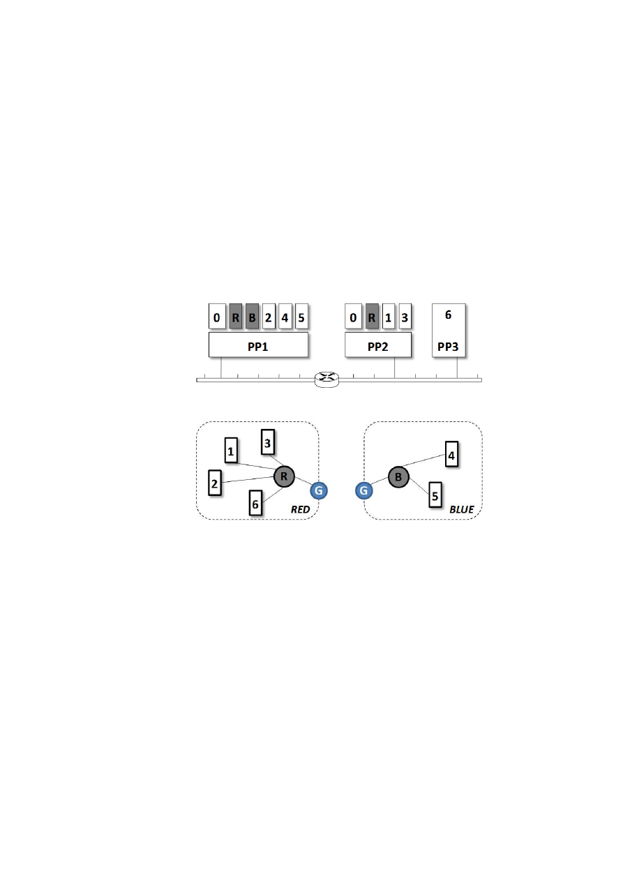
CHAPTER 7. SECURE VIRTUALIZED NETWORKING
71
(a) Physical view.
(b) Logical view.
Figure 7.1: An example TVD-based virtual network mapping:
R
and
B
are virtual
switches for red and blue TVDs;
G
is a virtual gateway that controls inter-TVD com-
munication (not shown in (a) for clarity).
OpenTC Document D05.6/V01 – Final R7628/2009/01/15/OpenTC Public (PU)

72
OpenTC D05.6 – Final Report of OpenTC Workpackage 5
7.2.1
High-level Objectives
This paper mainly considers virtual data centers that host multiple customers with po-
tentially conflicting interests. In this setting, our secure networking framework helps
meet the following functional and security objectives:
Virtual Networking The framework should support arbitrary logical network topolo-
gies that inter-connect virtualized and non-virtualized platforms alike.
Customer Separation The framework should provide sufficient separation guarantees
to customers such that data leakage between customer domains is minimal
1
.
Unified Policy Enforcement The framework should enforce domain policies within
and across customer domains in a seamless manner. The policies define integrity,
confidentiality, and isolation requirements for each domain, and information flow
control requirements between any two domains.
Autonomous Management The framework should deploy, configure and manage the
networking and security mechanisms in an automated manner.
7.2.2
Overview of the VNET Infrastructure
Our VNET infrastructure inter-connects groups of related VMs as though they were
on their own separate network fabric. As a result, pockets of virtual LAN (VLAN)
segments are formed across the data center. The central VLAN element is a virtual
switch, which regulates and isolates the network traffic for each segment. There is
a single virtual switch per VLAN segment. A VM appears on a particular VLAN
segment if one of its virtual network interface cards (vNICs) is “plugged” into one of
the switch ports on the virtual switch forming that segment.
The virtual switch behaves like a normal physical switch and coordinates traffic to
and from member VMs. Figure 7.1(b) illustrates two virtual switches
R
and
B
that
coordinate the subnet communication for red and blue segments. The virtual switch
logic resides either on the host OS of the virtualized platform, or on a dedicated VM
as shown in Figure 7.1(a). To satisfy security properties even when the traffic tra-
verses untrusted communication medium, additional VPN modules may be employed.
Similarly, additional network admission control (NAC) modules may be employed to
authenticate the VMs prior to VLAN admission.
7.2.3
Overview of the TVD Infrastructure
A TVD is represented by a set of distributed virtual processing elements (VPE) (e.g.,
VMs and virtual switches) and a communication medium interconnecting the VPEs.
The TVD provides a policy and containment boundary around those VPEs. At a high
level, the TVD policy has three aspects: (1) membership requirements for the TVD, (2)
interaction among VPEs of that TVD, and (3) interaction of the TVD with other TVDs
and the outside world. VPEs within each TVD can usually communicate freely and
securely with each other. At the same time, they are sufficiently isolated from outside
VPEs including those belonging to other TVDs. From a networking perspective, iso-
lation loosely refers to the requirement that a dishonest VPE in one TVD cannot send
1
Indirect communication channels such as covert and subliminal channels are outside the scope of this
paper.
OpenTC Document D05.6/V01 – Final R7628/2009/01/15/OpenTC Public (PU)

CHAPTER 7. SECURE VIRTUALIZED NETWORKING
73
messages to a dishonest VPE in another TVD, unless the inter-TVD policies explicitly
allow such data flow.
Each TVD has an associated infrastructure whose purpose is to provide a unified
level of security to member VPEs, while restricting the interaction with VPEs outside
the TVD to pre-specified, well-defined means only. Unified security within a domain
is obtained by defining and enforcing membership and communication requirements
that the VPEs and networks have to satisfy before being admitted to the TVD and for
retaining the membership. Unified security across domains is obtained by defining and
enforcing flow requirements that the VPEs have to satisfy to be able to interact with
VPEs in other TVDs. To do so, each TVD defines rules that regulate in-bound and
out-bound network traffic and restrict communication with the outside world.
The central element in the TVD infrastructure is the TVD master which keeps track
of high-level TVD policies and secrets. TVD masters maintain control over member
VPEs using TVD proxies. There is a single TVD master per TVD and a single TVD
proxy per physical platform. A VPE appears on a particular TVD if it complies with the
membership requirements enforced by the TVD proxy controlling that domain on that
physical platform. VPEs communicate freely within a TVD. Communication across
TVDs is controlled by entities configured by TVD proxies.
7.2.4
Overview of TVD-based Virtual Networking
VNET and TVD infrastructures play complementary roles in meeting the aforemen-
tioned high-level objectives. In particular, the VNET infrastructure provides the tools
and mechanisms to enable secure virtual networking in a data center. The TVD infras-
tructure defines unified domain policies, and automatically configures and manages
these mechanisms in conjunction with the policy. It also provides domain customers
the necessary tools to manage their TVDs. Any action by the customer is then seam-
lessly reflected on the underlying VNET infrastructure in an automated manner.
This two-layer architecture has many advantages:
1. The policy (TVD) and enforcement (VNET) layers are clearly separated from
each other, which yields a modular framework. As a result, a plethora of VNET
technologies can be deployed underneath the TVD infrastructure in place of the
current offering.
2. The policy layer is not restricted to network-type policies only. For example,
similar policies can be devised to configure and manage mechanisms to share
virtual storage between VMs in a single TVD.
3. The policy layer provides a high-level abstraction of the infrastructure to cus-
tomers, which in turn yields simpler administrative tools that are agnostic to the
complexities of the underlying VNET technology.
4. Automated deployment, configuration and management of customer TVDs are
desirable in a virtual data center that can effectively reduce operational costs
by easing the management burden, and mitigate insider threat by automating
administrative tasks.
OpenTC Document D05.6/V01 – Final R7628/2009/01/15/OpenTC Public (PU)
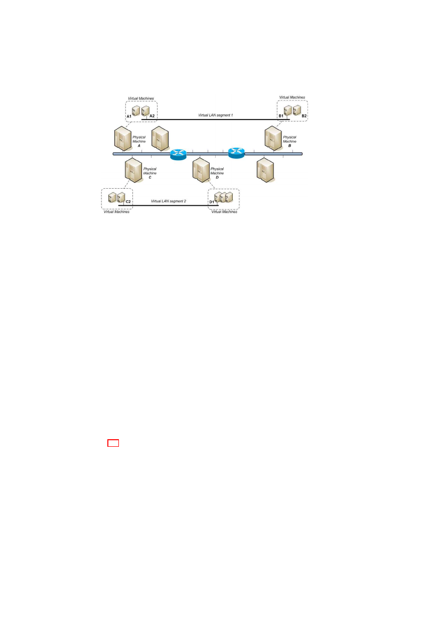
74
OpenTC D05.6 – Final Report of OpenTC Workpackage 5
Figure 7.2: An Example Physical to Virtual Mapping with two Virtual LAN Segments.
7.3
Networking Infrastructure
In this section, we present the network virtualization layer that enables the creation of
arbitrary virtual topologies on top of the underlying physical network. This layer also
provides the basic mechanisms to help enforce TVD admission and flow policies at a
higher level.
7.3.1
Aims and Requirements
Functional Requirements
The main aim of the VNET infrastructure is to allow groups of related VMs running
on separate physical machines to be connected together as though they were on their
own separate network fabric. For example, a group of related VMs may have to be
connected directly together on the same VLAN segment even though, in reality, they
may be at opposite ends of a WAN link separated by many physical LAN segments.
Further, multiple segmented virtual networks may have to be established on a single
physical network segment to achieve improved security properties such as network
isolation. Third, the VNET infrastructure needs to inter-operate with existing non-
virtualized entities (e.g., standard client machines on the Internet) and allow our virtual
networks to connect to real networks.
Figure 7.2 illustrates an example physical to virtual mapping. Physical machine
A hosts two VMs. One of them (A2) is connected into VLAN segment 1. Physical
machine B also hosts two VMs. One of them (B1) is also connected into VLAN seg-
ment 1. VM A1 and VM B1 appear as though they are connected together via a single
LAN segment even though in reality the physical network connecting them consists
of multiple LAN segments interconnected via routers. VMs C2 and D1 are also con-
nected together via VLAN segment 2. Traffic is isolated between VLAN segments so
machines C2 and D1 cannot see the traffic passing between A2 and B1 even though
they are sharing the underlying physical network infrastructure.
OpenTC Document D05.6/V01 – Final R7628/2009/01/15/OpenTC Public (PU)

CHAPTER 7. SECURE VIRTUALIZED NETWORKING
75
Attacker Model
Our research specifically focuses on virtual data centers that aim to separate customer
networks and protect network traffic even when the transmission lines are untrusted.
We mainly focus on network separation and protection; however, our policies and in-
frastructure are generic and can be applied to other requirements such as storage isola-
tion. A particular threat we consider here is the threat of malicious data center users that
can try to gain access to other customer networks for the purpose of stealing sensitive
information or rendering those systems unusable.
Additional threats could include
malicious users tapping untrusted transmission lines when data travels across a WAN;
malicious users injecting traffic into unauthorized network segments; or in a more ex-
treme case, a compromised virtual network device leaking all data passing through the
switch or router. These risks clearly reduce the benefits of machine consolidation in a
virtual data center. The risks also limit the guarantees that infrastructure owners would
put into service-level agreements when compared to the case of physical isolation of
the networks belonging to different customers.
Security Requirements
Our VNET infrastructure adheres to following security requirements to address these
threats in a virtual data center:
1. The infrastructure must provide logical isolation of VLAN segments. A rogue
segment must not be able to gain control of devices that belong to other VLANs
in the virtual data center.
2. The infrastructure must protect and separate the traffic generated by each VLAN
segment. VLANs must not be able to see, intercept or inject packets into traffic
originating from other VLANs.
3. Network connections can be established between VMs that belong to the same
VLAN segment and between VMs that belong to different VLAN segments (i.e.,
TVDs). The infrastructure must secure these connections whenever they are
established over untrusted physical medium.
4. The infrastructure must authenticate and sanity-check all VNET entities (virtual
or physical) including the management entities prior to admission to the particu-
lar VLAN segment.
7.3.2
Networking Infrastructure
One option for virtual networking is to virtualize at the IP level. However, to also
support non-IP protocols and IP support services (such as ARP) that sit directly on top
of the Ethernet protocol, we have chosen to virtualize at the Ethernet level.
Architecture Overview
Our VNET infrastructure employs a mixture of physical and virtual networking en-
tities to inter-connect physical and virtual machines with respect to the logical topol-
ogy. Physical networking entities include standard physical networking devices such as
VLAN-enabled switches and routers. Virtual networking entities include virtual net-
work interface cards (vNICs), virtual switches, virtual routers, and virtual gateways.
OpenTC Document D05.6/V01 – Final R7628/2009/01/15/OpenTC Public (PU)

76
OpenTC D05.6 – Final Report of OpenTC Workpackage 5
Table 7.1: Virtual components of the VNET infrastructure.
VNET
C
OMPO
-
NENT
F
UNCTIONALITY
Virtual NIC
Connects a virtual machine to a virtual switch
Virtual Switch
Provides centralised switching functionality per subnet
Performs address mapping and translation using switching ta-
ble
Provides logical traffic isolation between VLAN segments
EtherIP Module
Tunnels Ethernet and 802.3 packets via IP datagrams
Expands a LAN over a WAN or MAN
VLAN Module
Tags Layer 2 frames with the corresponding VLAN identifier
Provides traffic isolation on the physical switch
VPN Module
Encapsulates traffic in IP packets
Provides confidentiality and integrity over insecure medium
NAC Module
Enables port-based access control and compliance checking
prior to network admission
Virtual Router
Routes Layer 3 traffic between VMs on different VLAN seg-
ments
Virtual Gateway
Advertises routing information about the virtual network be-
hind it
Converts packets to and from the VNET encapsulated format
OpenTC Document D05.6/V01 – Final R7628/2009/01/15/OpenTC Public (PU)
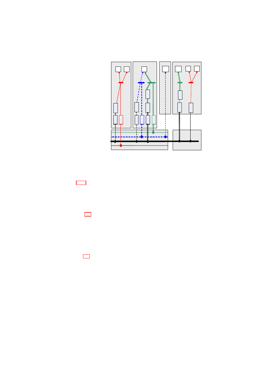
CHAPTER 7. SECURE VIRTUALIZED NETWORKING
77
vSwitches
VPN
VMs
& vNICs
E
the
rI
P
EtherIP
encapsulation
E
the
rI
P
VLAN-enabled
Physical Switch
TCP/IP
Host-3
Host-4
E
the
rI
P
T
a
gge
r
VLAN Tagging
Host-1
V
P
N
E
the
rI
P
E
the
rI
P
Host-2
T
a
gge
r
T
a
gge
r
T
a
gge
r
T
a
gge
r
T
a
gge
r
V
P
N
Figure 7.3: Components of the Secure Virtual Networking Infrastructure.
Table 7.3.2 provides a list of all virtual networking devices we employ in our networks
alongside standard physical devices (e.g., physical switches). In essence, a central vir-
tual switch per virtual LAN (VLAN) segment uses a combination of these devices and
modules to enable the virtualization of the underlying network and secure the com-
munication. We provide details on each virtual networking device in the following
sections.
Figure 7.3 illustrates how these components can be composed into a secure VNET
infrastructure that provides isolation between different VLANs (i.e., TVDs), where
each TVD is represented by a different color (red (solid), green (dashed), or blue (dou-
ble) line). Abstractly speaking, it is as if our secure VNET framework provides colored
networks (in which a different color means a different TVD) with security guarantees
(such as confidentiality, integrity, and isolation) to higher layers of the virtual infras-
tructure. VMs connect to the network using their vNICs through the corresponding
virtual switch for that VLAN; whereas a non-virtualized physical host, such as Host-3
in Figure 7.3, is directly connected to a VLAN-enabled physical switch without em-
ploying a virtual switch. A VM can be connected to multiple VLAN segments using a
different vNIC for each VLAN segment; hence, the VM can be a member of multiple
TVDs simultaneously. For example, the lone VM in Host-2 is part of two VLAN seg-
ments, each represented by a virtual switch with a different color; hence, the VM is a
member of both the blue and green TVDs.
Virtual Switching
Virtual switches enable network virtualization and co-ordinate all communication
within and across VLAN segments. Each VM has a number of vNICs where each can
be associated with at most one VLAN segment. Each VLAN segment is represented
OpenTC Document D05.6/V01 – Final R7628/2009/01/15/OpenTC Public (PU)

78
OpenTC D05.6 – Final Report of OpenTC Workpackage 5
by a virtual switch or a vSwitch, which behaves like a normal physical switch for that
segment. A VM appears on a particular VLAN if one of its vNICs is “plugged” into
one of the switch ports on the vSwitch. Ethernet broadcast traffic generated by a VM
connected to the vSwitch is passed to all VMs connected to that vSwitch. Like a real
switch, the vSwitch also builds up a forwarding table based on observed traffic so that
non-broadcast Ethernet traffic can be delivered point-to-point to improve bandwidth
efficiency.
To enable network virtualization, our vSwitches encapsulate or tag VM Ethernet
frames with VLAN identifiers using the EtherIP [52] and IEEE 802.1Q [49] modules,
respectively. Ethernet frames originating from the source host are handled differently
depending on whether the source host is virtualized and whether the destination host
resides in the same LAN. For a virtualized domain (e.g., Host-1 in Figure 7.3), each
frame is tagged using a VLAN tagging module. If the destination of the Ethernet
frame is a VM on another host that is connected to the same VLAN-capable switch
(e.g., another physical domain in a data center), this tag indicates the VLAN segment
to which the VM belongs. If the destination is a host that resides outside the LAN
domain (e.g., Host-4), the VLAN tag forces the switch to bridge the connection to an
outgoing WAN line (indicated by the black (thick) line in the VLAN-enabled physical
switch of Figure 7.3) that is connected to a router for further packet routing. In this
case, the VM Ethernet frames are encapsulated in IP packets to indicate the VLAN
segment membership. Lastly, if a non-virtualized physical host is directly connected
to the VLAN switch (e.g., Host-3), no tagging is required for the outgoing connection
from the host’s domain. In the absence of a trusted physical network, each VLAN
segment can employ an optional VPN layer to provide authentication, integrity, and
confidentiality.
EtherIP Encapsulation
EtherIP is a standard protocol for tunneling Ethernet and 802.3 packets via IP data-
grams and can be employed to expand a LAN over a Wide or Metropolitan Area Net-
work [52]. We employ EtherIP encapsulation as the standard mechanism to insert
VLAN membership information into Ethernet/802.3 frames. To do so, each tunnel
endpoint uses a special network device provided by the operating system that encapsu-
lates outgoing Ethernet/802.3 packets in new IP packets. We insert VLAN membership
information (i.e., the VLAN identifier) into the EtherIP header of each encapsulated
packet. The encapsulated packets are then transmitted to the other side of the tunnel
where the embedded Ethernet/802.3 packets are extracted and transmitted to the desti-
nation host that belongs to the same VLAN segment.
Address Mapping
The vSwitch component maps the Ethernet address of the en-
capsulated Ethernet frame to an appropriate IP address. This way, the encapsulated
Ethernet frame can be transmitted over the underlying physical network to physical
machines hosting other VMs connected to the same LAN segment that would have
seen that Ethernet traffic had the VMs actually been on a real LAN together. The IP
address chosen to route the encapsulated Ethernet frames over the underlying physical
network depends upon whether the encapsulated Ethernet frame is an Ethernet broad-
cast frame and also whether the vSwitch has built up a table of the locations of the
physical machines hosting other VMs on a particular LAN segment based on observ-
ing traffic on that LAN.
OpenTC Document D05.6/V01 – Final R7628/2009/01/15/OpenTC Public (PU)

CHAPTER 7. SECURE VIRTUALIZED NETWORKING
79
IP packets encapsulating broadcast Ethernet frames are given a multicast IP ad-
dress and sent out over the physical network. Each VLAN segment has an IP multicast
address associated with it. All physical machines hosting VMs on a particular VLAN
segment are members of the multicast group for that VLAN segment. This mechanism
ensures that all VMs on a particular VLAN segment receive all broadcast Ethernet
frames from other VMs on that segment. Encapsulated Ethernet frames that contain
a directed Ethernet address destination are either flooded to all the VMs on a partic-
ular VLAN segment (using the IP multicast address as in the broadcast case) or sent
to a specific physical machine IP address. This depends upon whether the vSwitch
component on the encapsulating VM has learned the location of the physical machine
hosting the VM with the given Ethernet destination address based on traffic observation
through the vSwitch.
Requirements Revisited
EtherIP can be used over arbitrary Layer 3 networks. The
decision to encapsulate Ethernet frames from VMs within IP packets allow us to con-
nect different VMs to the same VLAN segment so long as the physical machines host-
ing those VMs have some form of IP based connectivity between them, even a WAN
link. There are no restrictions on the topology of that physical network.
To allow routing within virtual networks we use virtual routers that reside on
VMs with multiple vNICs. The interface cards are plugged into ports on the differ-
ent vSwitches that it is required to route between. Standard routing software is then
configured and run on the routing VM to provide the desired routing services between
the connected VLAN segments.
To allow for communication with non-virtualized systems we provide a virtual
gateway that simply is another VM with two vNICs. One vNIC is plugged into a
port on a vSwitch; the other one is bridged directly on to the physical network. The
gateway has two main roles: (1) It advertises routing information about the virtual net-
work behind it so that hosts in the non-virtualized world can locate the VMs that reside
on a virtual network, and (2) it converts packets to and from the encapsulated format
required of our virtual networks.
VLAN Tagging
VLAN tagging is a well-established VNET technology that provides isolation of
VLAN segments on physical network equipment [49]. We employ VLAN tagging
as an alternative to Ethernet encapsulation for efficiency purposes. For example, in a
virtualized datacenter a VLAN-enabled switch may be used that yield increased per-
formance over EtherIP encapsulation.
Each VLAN segment employs its own VLAN tagging module to tag its Ethernet
frames. This module resides within the hypervisor or host OS that facilitates the net-
working capabilities, captures packets originating from VMs, and tags those with the
ID of the VM’s VLAN before sending them onto the physical wire. On the receiv-
ing side, the module removes the VLAN tag and passes the packets untagged into the
destination VM(s). Packets are only tagged when they have to be transmitted over the
physical network. VMs are unaware of the VLAN tagging and send/receive packets
without any VLAN information.
To handle VLAN tagged packets, the physical network equipment needs to support
IEEE 802.1Q and be configured accordingly. As an example, if a machine hosts a VM
that is part of VLAN 42, then the switch port that is used by that machine needs to
be assigned to that specific VLAN 42. A physical machine can host multiple VMs
OpenTC Document D05.6/V01 – Final R7628/2009/01/15/OpenTC Public (PU)

80
OpenTC D05.6 – Final Report of OpenTC Workpackage 5
which can be on different VLANs, therefore a switch port might be assigned to mul-
tiple VLANs (which creates a
VLAN trunk
between the host and the switch port).
Whenever a host deploys a new VM or removes a VM, the switch port might need to
be reconfigured. Ideally, this can be done in a dynamic and automated fashion, e.g.,
through network management protocols. Physical switches only pass packets between
machines within the same VLAN, which provides an additional isolation mechanism
to our VLAN-capable vSwitch that is deployed on all of the hosts.
Address Mapping
VLAN tagging does not require any extra address mapping mech-
anism. VMs discover address information of other VMs using standard discovery pro-
tocols as in a non-virtualized environment. However, the vSwitch module that runs
on each physical machine learns Ethernet addresses attached to the vSwitch ports by
inspecting packets (in the same way as physical switches do) and builds up lookup ta-
bles (one table per vSwitch / VLAN) that store information about the location of VMs
based on their Ethernet addresses. The vSwitch uses this table to decide if a packet has
to be passed to a local VM or onto the physical network to be delivered to a remote
machine.
There is no explicit mapping of broadcast / multicast addresses as in the case of
EtherIP encapsulation. Instead, physical switches that manage the underlying network
infrastructure ensure that broadcast and multicast traffic never crosses VLAN bound-
aries. Broadcast and multicast packets that are tagged with a VLAN ID are passed to
all switch ports that are associated with that particular VLAN, but no other ports. When
those packets enter the physical machine that runs our vSwitch module, the packets are
only passed into VMs that are attached to vSwitch ports that are assigned to the VLAN
matching the ID in the packets.
Requirements Revisited
VLAN tagging can be used over arbitrary Layer 3 net-
works. However, unlike EtherIP a solution based on pure VLAN tagging is limited
to a LAN environment and cannot be deployed over WAN links. VLAN tagging highly
depends on support from the physical network equipment that is managing the underly-
ing infrastructure. For example, physical switches need to support the VLAN tagging
standard that we use when tagging our packets in our vSwitch module (IEEE 802.1Q)
and need to be configured to handle tagged packets in order to provide appropriate
isolation between VLANs.
A VLAN is a logical network segment and by default network traffic such as broad-
cast messages or ARP communication is limited to a single VLAN. However, it is
also possible to allow communication between (virtual) machines of different VLANs
through
Inter-VLAN routing
. There are multiple well-known and standardized
solutions to allow this. For example, most physical switches facilitate fast Layer 3
routing between multiple VLANs. This solution offers high performance, but requires
that routing policies can be configured on the physical network devices – ideally in
an automated fashion. As an alternative, we can also deploy specific VMs that have
multiple network interfaces in multiple VLANs and route packets between those – as
in the EtherIP encapsulation approach.
VLAN tagging inherently supports communciation with non-virtualized systems.
This is because VLAN tagging is a widely used standard that is deployed within in-
frastructures where physical machines do not run any (network) virtualization soft-
ware. There is no need for a virtual gateway as in the EtherIP case. Instead, physical
switches can be configured to remove VLAN tags from packets when transmitting on
OpenTC Document D05.6/V01 – Final R7628/2009/01/15/OpenTC Public (PU)

CHAPTER 7. SECURE VIRTUALIZED NETWORKING
81
a port where the connected endpoint is not VLAN-capable, and add tags whenever
packets are received on that specific port. In that case those endpoints are completely
unaware of VLANs, and receive and transmit packets without any VLAN information.
Secure Networking
In addition to EtherIP and VLAN tagging modules, our vSwitches employ network
access modules for admission control and optional VPN modules for packet tunneling.
Network access control or NAC is an IEEE 802.1X standard for port-based access con-
trol [50]. NAC can be implemented by various network devices which in turn force a
host (supplicant) go through an authentication process prior to using services provided
by the device (e.g., being admitted to the network). All network traffic originating
from the supplicant is blocked prior to admission except the NAC traffic itself. NAC
requests are received by an access point (authenticator) and forwarded to an authenti-
cation server (AS) (e.g., a RADIUS server). The AS runs a choice of authentication
protocol specified by the extensible authentication protocol (EAP). It returns the verdict
to the authenticator as a result of which access is granted to the supplicant or denied.
The NAC module is incorporated into the vSwitch admission process during which the
requesting VM is authenticated prior to TVD admission. The choice of which authen-
tication method is dictated by the high-level TVD policies.
Encapsulation and tagging alone do not provide any guarantees on the confiden-
tiality and integrity of the packets / frames that are transmitted on the wire. Without a
proper VPN layer, these schemes are only suitable for routed and controlled networks
in which the underlying physical infrastructure is trusted, e.g., a virtualized data cen-
ter. In cases no such guarantees can be given (e.g., over a WAN link), we employ an
implementation of IPSec [63] to tunnel VLAN communication in a confidential and an
integrity-preserving way. To do so, the VPN module employs the Encapsulating Secu-
rity Payload (ESP) of IPSec that encapsulates IP packets and applies block encryption
to provide confidentiality and integrity. This adds an additional layer of packet encap-
sulation on top of EtherIP. The optional VPN module is incorporated into the vSwitch.
7.4
TVD Infrastructure
In this section, we present the trusted virtual domain (TVD) infrastructure, the com-
position of its components to form TVDs and to enforce TVD policies, and describe
the management of this infrastructure. We first focus on the static behavior of a secure
network virtualization framework that is already up and running. Later, in Section 7.5,
we focus on the more dynamic aspects of the framework, including establishment and
deployment of the secure virtual infrastructure.
7.4.1
Security Objectives and Policies
Security policies for a TVD can be grouped into two categories: intra-TVD policies
that enforce security within a TVD and inter-TVD policies that enforce security across
TVDs.
Security within a TVD
Within a TVD, all VPEs can freely communicate with each other while observing
TVD-specific integrity and confidentiality requirements. Inside a data center, this
OpenTC Document D05.6/V01 – Final R7628/2009/01/15/OpenTC Public (PU)

82
OpenTC D05.6 – Final Report of OpenTC Workpackage 5
trusted network may be achieved without additional protection mechanisms. On poten-
tially insecure networks, secure intra-TVD communication requires an authenticated
and encrypted channel (e.g., using IPsec)
2
.
Given a set
T
of trusted virtual domains, one way of formalizing secure communi-
cation requirements as a domain-protection function
P
:
T
→
2
{
c,i,s
}
, which describes
the subset of security objectives (confidentiality, integrity protection, and isolation) as-
signed to a particular TVD. In TVD context, integrity means that a VPE cannot inject
“bad” messages and pretend they are from another VPE. Confidentiality refers to the
requirement that two honest VPEs (in the same TVD or different TVDs) can commu-
nicate with each other without an eavesdropper learning the content of the communi-
cation
3
. Isolation means that each TVD can enforce its security policy independently
of other TVDs that share the same infrastructure in a data center. In that respect a TVD
must be shielded from policy violations in other TVDs.
Admission control and membership management are crucial aspects of TVDs that
help meet these security objectives. VPEs that seek TVD membership may be required
to prove their eligibility either periodically or on request. For example, prospective
members may be required to possess certain credentials such as certificates or to prove
that they satisfy certain properties [96] prior to admission to the TVD in a certain role.
The conditions may vary for different roles of VPEs. For example, servers and work-
stations may have different TVD membership requirements. Similarly, the security
requirements on internal machines are usually weaker than for machine acting in a
gateway role. Overall, a TVD should be able to restrict its membership to machines
that satisfy a given set of conditions for each given role. Some VPEs may be part of
more than one TVDs, in which case they would have to satisfy the membership require-
ments of all the TVDs they are part of. Note that to enable multiple TVD membership,
the individual TVD membership requirements must be conflict-free.
One way of formalizing the membership requirements for a set
T
of trusted virtual
domains is to define a function
R
:
T
→
R
that identifies the set of unique roles
R
for a given TVD. We then use a function
M
:
R
→
2
P
, where
(
P,
≤
)
is a lattice of
security properties to identify the required security properties for each given role for
that TVD. A machine
m
with a set
p
m
of security properties may be permitted to join
the TVD
t
in role
r
iff
r
∈
R
(
t
)
and
∀
p
∈
M
(
r
) :
∃
p
′
∈
p
m
such that
p
′
≥
p
. In other
words,
m
is permitted to join
t
iff there is at least one property of
m
that satisfies each
security requirement of
r
.
Security across TVDs
Inter-TVD security objectives are independently enforced by each of the individual
TVDs involved. To facilitate such multilateral enforcement, global security objectives
are decomposed into per-TVD security policies. The advantage of such a decentral-
ized enforcement approach is that each TVD is shielded from security failures in other
TVDs, hence enforce domain isolation. Security objectives may take different forms;
here, we focus on information flow control among the TVDs and multi-TVD member-
ships.
An information flow control matrix is a simple way of formalizing the system-wide
flow control objectives. Table 7.2 shows a sample matrix for three TVDs:
T V D
α
,
2
A network is trusted with respect to a TVD security objective if it is trusted to enforce the given objective
transparently. For example, a server-internal Ethernet can often provide confidentiality without any need for
encryption.
3
Covert communication channels are outside the scope of this paper.
OpenTC Document D05.6/V01 – Final R7628/2009/01/15/OpenTC Public (PU)

CHAPTER 7. SECURE VIRTUALIZED NETWORKING
83
Table 7.2: Example TVD Policy Specification for Three TVDs
from:
to:
TVD
Role
T V D
α
T V D
β
T V D
γ
T V D
α
gate
1
∗
0
∗
P
αγ
T V D
α
internal
1
∗
T V D
β
gate
0
∗
1
∗
0
T V D
β
internal
1
∗
T V D
γ
gate
P
γα
P
γβ
1
T V D
γ
internal
1
∗
Table 7.3: Components of the TVD infrastructure.
TVD
C
OMPO
-
NENT
F
UNCTIONALITY
TVD Master
A global policy and credential repository per TVD that provisions
TVD proxies onto each physical host.
TVD Proxy
A local TVD master delegate, policy enforcer, and credential
repository per physical host per TVD.
TVD
Co-
ordinator
A local TVD factory per physical host that spawns TVD proxies
on request by TVD masters.
T V D
β
, and
T V D
γ
. Each matrix line represents a policy elements that specifies for a
given role of a given domain, what other domains it may connect to. The
1
elements
along the matrix diagonal convey the fact that any connection is allowed while a
0
disallows information flow.
While these two policies will later be enforced by allowing or disallowing logi-
cal connections, gateway machines can also enforce further application-level policies.
These policies
P
refine the all-flow policy
1
by allowing some flows while disallowing
others. In order to allow flow from a machine
A
playing Role
T V D
A
/Role
A
to ma-
chine
B
playing
T V D
B
/Role
B
, both corresponding policies need to permit the flow.
E.g., if
P
αβ
=
0
in Table 7.2, then
P
αγ
and
P
γβ
should not be inadvertedly
1
. Other-
wise, indirect information flow from
T V D
α
to
T V D
β
would be unconstrained, which
would contradict with
P
αβ
and result in a policy conflict.
The TVD policy also includes multi-TVD membership policy, where a TVD spec-
ifies whether a VPE in a certain role can hold another role in the same TVD or other
roles of other TVDs. This is formalized by multi-membership function
M
′
:
R
→
2
R
that assigns the subset of roles of other domains that can be assumed by a given VPE.
At the time of TVD policy specification, it is important to ensure that there is no conflict
between the various policy forms, e.g., if the information flow control policy specifies
that there should be no information flow between
T V D
α
and
T V D
β
, then the multi-
TVD membership restrictions cannot allow any VM to simultaneously be a member of
T V D
α
and
T V D
β
.
7.4.2
TVD Components
A TVD infrastructure consists of a single TVD master and multiple TVD proxies that
act as a delegate for that TVD on each physical host. We also use a local TVD co-
OpenTC Document D05.6/V01 – Final R7628/2009/01/15/OpenTC Public (PU)

84
OpenTC D05.6 – Final Report of OpenTC Workpackage 5
ordinator per physical platform to spawn all TVDs for that platform during TVD pro-
visioning. Table 7.4.1 lists each component and its role in the TVD infrastructure.
TVD master
The TVD master plays a central role in the management and auto-deployment of each
TVD. We refer to the TVD master as a single logical entity for each TVD, although its
implementation may be distributed. The TVD master is trusted by the TVD infrastruc-
ture and the VPEs that are members of the TVD. Known techniques based on Trusted
Computing can be used to validate the integrity of the TVD master by verifying its
software configuration. The TVD master can be hosted on a physical machine or a
virtual machine. In the case of a VM implementation, the PEV architecture proposed
by Jansen et al. [55] can be used to obtain policy enforcement and compliance proofs
for the purpose of assessing the TVD master’s trustworthiness.
The TVD policy is defined at the TVD master by the domain administrator (e.g.,
the administrator of a data center hosting multiple TVDs agrees on a policy with each
customer). The TVD master has the following responsibilities:
1. distributing the TVD policy and other TVD credentials (such as VPN key) to the
TVD proxies and informing them of any updates,
2. determining the suitability of a platform to host a TVD proxy (described be-
low) and periodically assessing the platform’s continued suitability to host VPEs
belonging to the TVD.
3. maintaining an up-to-date view of the TVD membership which includes a list of
TVD proxies and the VPEs hosted on their respective platforms.
TVD proxy
On every host that may potentially host a VM belonging to the TVD, there is a local
delegate of the TVD master, called the TVD proxy. The TVD proxy is the local enforcer
of the TVD policies on a given physical platform. At the time of its creation, the TVD
proxy receives the TVD policy from the TVD master. Upon an update to the TVD
policy (by a domain administrator), renewal of TVD credentials, or refresh of TVD
VPN keys at the TVD master, the master conveys the update to the TVD proxies.
The TVD proxies on a given platform are independent. Although TVD proxies
are trusted, TVD proxies on the same platform should be sufficiently isolated from
each other. For example, a TVD proxy should not be able to access private TVD
information (such as policies, certificates, and VPN keys) belonging to another TVD
proxy. For improved isolation, each TVD proxy on the platform may be hosted in
a separate infrastructure VM, which is different from a VM hosting regular services,
called production VM. On a platform with the Trusted Platform Module or TPM [115],
isolation can further be improved by TPM virtualization [13], assigning a separate
virtual TPM to each infrastructure VM, and using the virtual TPM as the basis for
storing private TVD information.
A TVD proxy must only be able to interact with VMs hosted on the platform be-
longing to the same TVD. As we describe below, that requirement is enforced by a
local TVD co-ordinator. The responsibilities of the TVD proxy are:
Configuration of the Local TVD vSwitch The TVD proxy configures the local TVD
vSwitch on a given host based on TVD policy. For example, if the TVD policy
OpenTC Document D05.6/V01 – Final R7628/2009/01/15/OpenTC Public (PU)

CHAPTER 7. SECURE VIRTUALIZED NETWORKING
85
specifies that information confidentiality is an objective, then the TVD proxy
enables all traffic through the vSwitch to pass through the VPN module and
provides the VPN key to the module.
Caching of the TVD Information The TVD proxy maintains private TVD informa-
tion such as policies, certificates, and VPN keys.
Status Reports to the TVD Master Upon request or periodically, the TVD proxy
provides a platform status report to the TVD master. The report includes in-
formation such as the number of VMs belonging to the TVD and their unique
addressable identifiers and the current vSwitch configuration. The status report
also serves as an “I am alive” message to the TVD master, and helps the TVD
master to keep an updated list of TVD proxies that are connected to it.
Enforcement of Admission Requirements for VMs into the TVD A VM’s virtual
NIC is attached to a vSwitch only after the TVD proxies of the switch’s and
the machine’s domain approve this attachment. Note that while the TVD proxy
of the switch prevents admission of non-compliant machines, the TVD proxy of
the machine prevents outflow into untrusted peer domains.
Continuous Enforcement of TVD Policy The TVD proxy is responsible for contin-
uous enforcement of TVD policy despite updates to the policy and changing
configuration of the platform and member VMs. Upon receiving an update to
the TVD policy from the TVD master, the TVD proxy may re-configure the
vSwitch, and re-assess member VMs’ membership to reflect the updated policy.
Even without any policy update, the TVD proxy may be required by TVD policy
to periodically do such re-configuration and re-assessment.
Local Common TVD Coordinator (LCTC)
The Local Common TVD Coordinator or LCTC is present on every platform (hence,
the word local in the name) on which a TVD element has to be hosted. The LCTC
itself does not belong to any single TVD (hence, the word common in the name). The
LCTC is part of the minimal TCB
4
on every TVD-enabled platform.
The LCTC is the entity that a TVD master or a system administrator contacts to
create a new TVD proxy on the platform. For this purpose, the LCTC must be made
publicly addressable and knowledgeable about the identities of the entities that may
potentially request the creation.
The LCTC has two main responsibilities, namely (1) creation of new TVD proxies
on the local platform, (2) restricting access of TVD proxies only to VMs belonging
to their respective TVDs. The LCTC maintains a list of VMs currently hosted on
the platform, a list of TVD proxies currently hosted on the platform, and a mapping
between the VMs and the TVDs they belong to.
7.4.3
Establishment of the TVD Infrastructure
Preparing a Platform to Host a given TVD
The initial step for establishing a TVD is to create the TVD master (step 0 in Figure 7.5)
and initialize the master with the TVD requirements (as formalized above) and the
4
On a Xen-based platform, the minimal TCB consists of the LCTC, Xen Dom0, the Xen hypervisor, and
the underlying hardware.
OpenTC Document D05.6/V01 – Final R7628/2009/01/15/OpenTC Public (PU)

86
OpenTC D05.6 – Final Report of OpenTC Workpackage 5
policy. The output of the step is a TVD object that contains the TVD’s unique identifier,
i.e., the TVD master’s URL and public key.
Once the TVD master has been initialized, the TVD is ready for being populated
with member entities, such as platforms and VPEs. A VPE becomes admitted to a TVD
after the successful completion of a multi-step protocol (steps 1 and 2 in Figure 7.5):
1. The LCTC on a physical platform creates a TVD proxy for the given domain and
initializes it with the URL and public key of the TVD master.
2. The TVD proxy sets up a secure, authenticated channel with the TVD master
using standard techniques. This includes a validation whether the physical plat-
form satisfies the admission requirements of this specific TVD.
3. The TVD proxy indicates the security and functional capabilities of the physical
machine. Using the capability model, the TVD master determines which addi-
tional mechanisms must be provided at the level of the virtual infrastructure. For
example, if a TVD requirements specification includes isolation and the physi-
cal infrastructure does not have that capability, then special (VLAN tagging or
VPN) modules must be instantiated within the Dom0 of physical machines host-
ing VMs that are part of the TVD.
4. The TVD master then replies to the TVD proxy with the TVD security policy
(such as flow control policies between VMs belonging to different TVDs hosted
on the same physical machine) and additional mechanisms that must be provided
at the virtualization level. The TVD proxy also obtains the TVD credentials
needed for network security.
5. The TVD proxy then instantiates and configures the required TVD-specific mod-
ules (e.g., vSwitch, VLAN tagging module, encapsulation module, VPN module,
policy engine, etc.) according to the TVD policy. After this step, the physical
machine is ready to host a VM belonging to the TVD.
Adding a VPE to a Requested Domain
Once the platform is ready to host VPEs that are members of a given TVD, a VPE can
join the TVD by being connected to the corresponding vSwitch as follows:
1. A VPE requests to join a given domain (identified by master URL and public
key) playing a given role.
2. The VPE runs a credential validation protocol with the TVD proxy of the domain
that it intends to join. The required credentials usually depend on the role to play.
3. The TVD proxy admits the machine to the domain and connects it with the re-
quested resources such as the domain-internal network.
Connecting a VPE to a Requested Domain
Once a VPE has been assigned to a domain, it may request connection to networks of
other domains:
1. A VPE requests to connect a given virtual network adapter to the network of a
second domain (identified by master URL and public key).
OpenTC Document D05.6/V01 – Final R7628/2009/01/15/OpenTC Public (PU)

CHAPTER 7. SECURE VIRTUALIZED NETWORKING
87
2. The VPE runs a credential validation protocol with the TVD proxy of the domain
of the vSwitch.
3. The TVD proxy of the domain is asked whether connection to this target TVD is
permitted.
4. The virtual network of the VPE is connected to the vSwitch.
7.5
Auto-deployment of Trusted Virtual Domains
Figure 7.4 shows the steps involved in automatic deployment of secure virtual infras-
tructures as TVD configurations. Figure 7.5 shows the steps involved in the establish-
ment and management of a single TVD.
First, the virtual infrastructure topology must be decomposed into constituent
TVDs, along with associated security requirements and policy model. Second, a capa-
bility model of the physical infrastructure must be developed. Capability modeling is
essentially the step of taking stock of existing mechanisms that can be directly used to
satisfy the TVD security requirements. In this paper, we consider the case where both
steps are done manually in an offline manner; future extensions will focus on automat-
ing them and on dynamically changing the capability models based on actual changes
to the capabilities.
7.5.1
Capability Modeling of the Physical Infrastructure
Capability modeling of the physical infrastructure considers both functional and secu-
rity capabilities. The functional capabilities of a host may be modeled using a function
C
:
H
→ {
V LAN, Ethernet, IP
}
, to describe whether a host has VLAN, Ethernet,
or IP support. Modeling of security capabilities includes two orthogonal aspects: the
set of security properties and the assurance that these properties are actually provided.
Table 7.4 lists some examples of security properties and Table 7.5 gives examples of
the types of evidence that can be used to support security property claims.
7.5.2
Instantiation of the Right Networking Modules
The TVD proxy uses the instructions given to it by the TVD master to determine the
right protection mechanisms to instantiate on the local platform for the TVD network
traffic, and accordingly configures the local TVD vSwitch.
Suppose that isolation of TVD traffic is a requirement. Then, VLAN tagging alone
would suffice provided the TVD spans only the LAN and the physical switches on the
LAN are VLAN-enabled (i.e., it must support IEEE 802.1Q and must be appropriately
configured); in that case, a VLAN tagging module would be created and connected
to the vSwitch. If the TVD spans beyond a LAN, then VLAN tagging must be used
in conjunction with EtherIP encapsulation. In this case, the VLAN tagged packet is
encapsulated in a new IP packet and tunneled to the other side, where the original
VLAN tagged packet is extracted and transmitted on the VLAN. If VLAN-enabled
switches are not available, then EtherIP alone would suffice for isolation.
By itself, EtherIP does not provide integrity or confidentiality of the packets.
Hence, when those properties are required, EtherIP is suitable only on routed and
trusted networks, e.g., EtherIP would be suitable for traffic between two vSwitches
OpenTC Document D05.6/V01 – Final R7628/2009/01/15/OpenTC Public (PU)

88
OpenTC D05.6 – Final Report of OpenTC Workpackage 5
hosted on different physical platforms that are not connected to the same VLAN switch
in a datacenter or corporate environment.
If integrity or confidentiality are required properties and the underlying network is
not trusted, then IPsec is used in conjunction with EtherIP and VLAN. In that case,
the TVD proxy will create the VPN module, initialize it with the VPN key obtained
from the master, and connect it to the vSwitch. Since IPsec only operates on IP packets
and not Ethernet or VLAN ones, double encapsulation is needed: EtherIP is used to
first encapsulate the Ethernet or VLAN packets, followed by IPsec encapsulation and
encryption (using the VPN key).
7.5.3
Inter-TVD Management
Separation of flow control and transport. Transport part is based on today’s connec-
tion between autonomous systems based on BGP. Flow control is based on firewalls.
Flow control part figures out whether a packet can get out to the other TVD and what
protection mechanism is needed (e.g., encryption). After flow control, border gateway
takes care of routing the packet to the border gateway at other end. Contact master
for obtaining capability of the other side gateway. Master-master communication for
generating shared key for encryption for inter-TVD traffic.
One firewall for each other TVD, or new rules for another new TVD on the same
firewall?
Inter-TVD management deals with the interchange fabric for communication be-
tween TVDs, enforcement of inter-TVD flow control policies, external zones (IP versus
Ethernet), approval of admission requests by TVD-external entities (such as a new VM)
to join the TVD, and linking such entities with the appropriate TVD master.
As shown in Figure 7.2, inter-TVD communication can be broadly classified into
three types: (1) controlled connections, represented by policy entries in the matrix,
(2) open or unrestricted connections, represented by
1
elements in the matrix, and (3)
closed connections, represented by
0
elements in the matrix.
Controlled connections restrict the flow between TVDs based on specified poli-
cies. The policies are enforced at TVD boundaries (at both TVDs) by appropriately
configured firewalls. The TVD master may push pre-checked configurations (derived
from TVD policies) into the firewalls during the establishment of the TVD topology.
If available, a management console at the TVD master may be used to manually set
up and/or alter the configurations of the firewalls. A TVD firewall has multiple vir-
tual network interface cards, one card for the internal VLAN that the firewall protects
and one additional card for each TVD that the members of the protected TVD want to
communicate with.
Open connection between two TVDs means that any two machines in either TVD
can communicate freely. In such a case, the firewalls at both TVDs would have virtual
network cards for the peer domain and simply serve as bridges between the domains.
For example, different zones in a given enterprise may form different TVDs, but may
communicate freely. As another example, two TVDs may have different member-
ship requirements, but may have an open connection between their elements. Open
connection between two domains may be implemented using an unlimited number of
virtual routers. In a physical machine that is hosting two VMs belonging to different
TVDs with an open connection, the corresponding vSwitches may be directly con-
nected. Communication between two TVDs, while open, may be subject to some con-
straints and monitoring. For example, a TVD master may permit the creation of only
OpenTC Document D05.6/V01 – Final R7628/2009/01/15/OpenTC Public (PU)
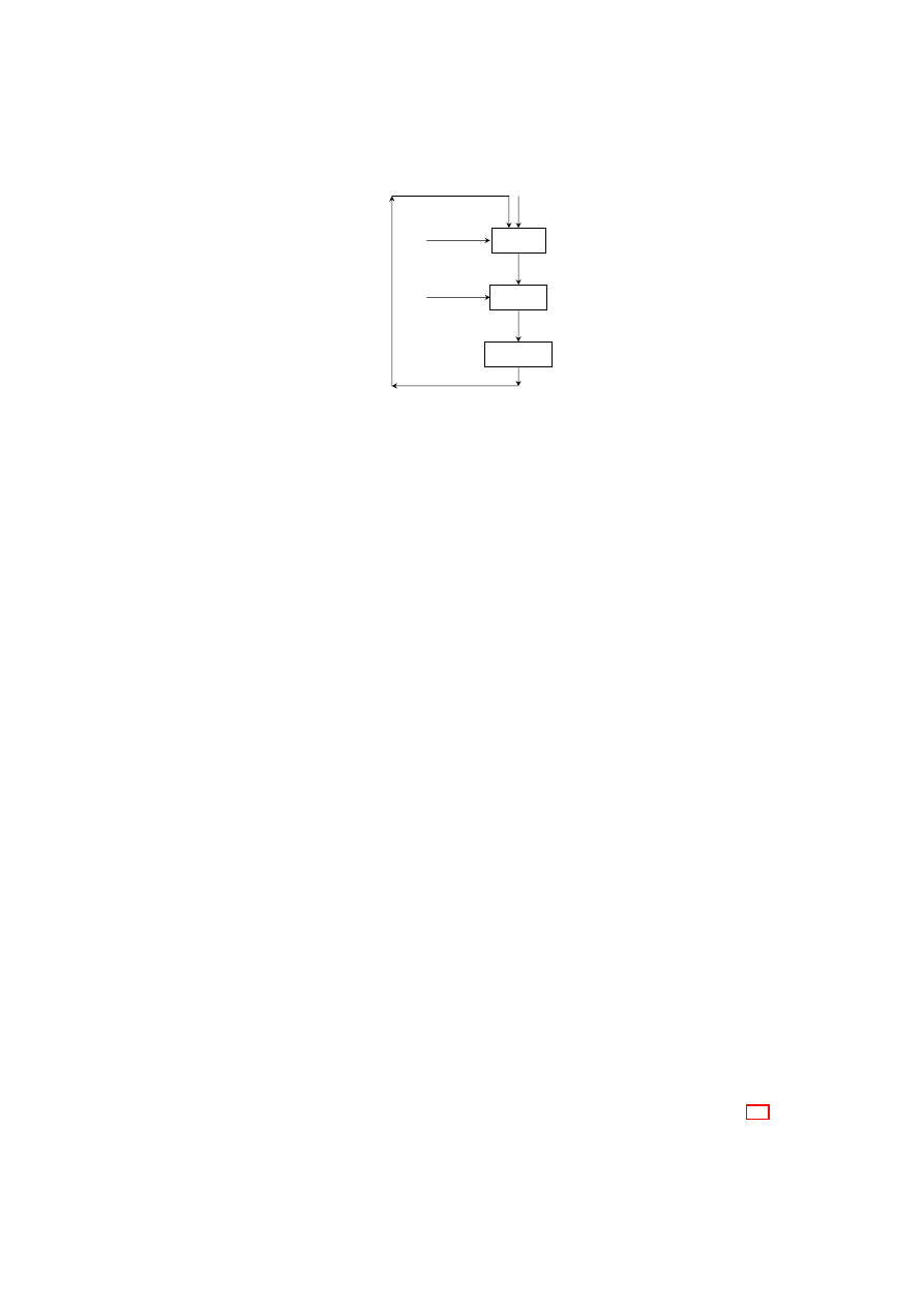
CHAPTER 7. SECURE VIRTUALIZED NETWORKING
89
Security
Policy
Per-host
Extensions
Global
Configuration
TVD
Requirements
Mechanisms
Required
Deployment Planning
& Management
TVD Policy
Model
Capability
Model
Revised Requirements,
Policies, or Capabilities
Figure 7.4: Steps in Auto-Deployment of TVDs.
a few virtual routers on certain high-assurance physical machines for information flow
between the TVD and another TVD with which the former has an open connection.
A closed connection between two TVDs can be seen as a special case of a con-
trolled connection in which the firewall does not have virtual network card for the peer
TVD. In addition to the firewall filtering rules, the absence of the card will prevent any
communication with the peer TVD.
Special VMs (e.g., gateways) may have membership in two or more open TVDs
simultaneously. Consider a VM that is first a member of TVD
α
. The VM has one
virtual NIC that is connected to the vSwitch of TVD
α
. Now, suppose that the VM
needs to be a member of both TVD
α
and TVD
β
simultaneously. For this purpose,
the VM needs to have two virtual NICs, one connected to the vSwitch of TVD
α
and
the other connected to that of TVD
β
. Any VM request to create a new virtual NIC has
to be approved by the TVD proxy, which grants the approval only if TVD
α
is an open
TVD and TVD
α
’s policies allow such a dual membership. Initially, the new virtual
NIC is connected to the default network, and the VM sends a membership request for
TVD
β
to the local TVD proxy (if present) or a remote TVD master. If TVD
β
’s
policies allow for dual membership with TVD
α
and the VM satisfies other admission
requirements for TVD
β
, then proxy for TVD
β
will connect the new virtual NIC to the
vSwitch of TVD
β
. At this point, the VM is connected to the VLANs of both TVDs.
7.5.4
Intra-TVD Management
Intra-TVD management is concerned with TVD membership (including mutual au-
thentication), communication within a TVD, and the network fabric (i.e., internal topol-
ogy) of a TVD. Prior to membership negotiation, mutual authentication requires both
the TVD infrastructure (TVD proxy or the master in the absence of a proxy) and the
client (i.e., the prospective member VM) to authenticate itself to each other. For TVD
authentication, we employ TVD certificates that are issued and distributed for each
TVD. For client authentication, we use the IEEE 802.1X standard for network access
control (NAC). The latter employs a port-based authentication scheme and a third-party
authenticator (e.g., a RADIUS server) to authenticate the VM. In this setting, the TVD
proxy acts as the authenticator that forwards the request to the authentication server
and interprets the result. We describe client authentication in detail in Sections 7.5
OpenTC Document D05.6/V01 – Final R7628/2009/01/15/OpenTC Public (PU)
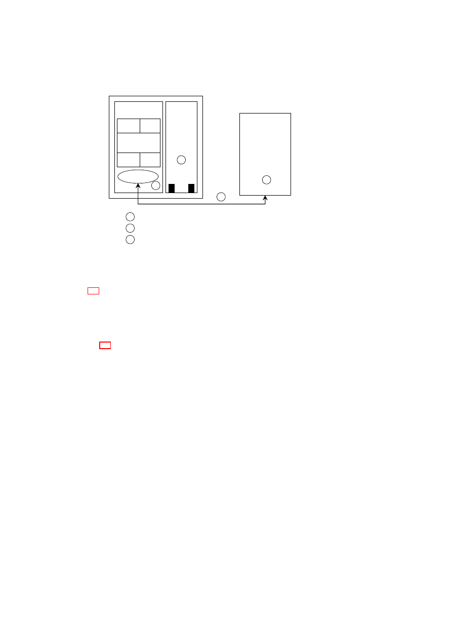
90
OpenTC D05.6 – Final Report of OpenTC Workpackage 5
TVD Master
DomU
Dom0
TVD proxy
TVD-specific
Modules
EtherIP VLAN
…..
Policy
Engine
TVD-specific
Modules
EtherIP VLAN
…..
Policy
Engine
vNICs
…
0
TVD object
←
create TVD (TVD requirements, policy model)
create TVD Proxy (Master URL)
1
0
2
connect VM to TVD (TVD object)
1
1
2
Figure 7.5: Steps in Populating a TVD.
and 7.6.
Intra-TVD policies specify the membership requirements for each TVD, i.e., the
conditions under which a VM is allowed to join the TVD. At a physical machine host-
ing the VM, the requirements are enforced by the machine’s TVD proxy in collabo-
ration with networking elements (such as vSwitches) based on the policies given to
the TVD proxy by the TVD master. We describe TVD admission control in detail in
Section 7.5.
A VLAN can be part of at most one TVD. For completeness, each VLAN that
is not explicitly part of some TVD is assumed to be a member of a dummy TVD,
T V D
∆
. Although a VLAN that is part of
T V D
∆
may employ its own protection
mechanisms, the TVD itself does not enforce any flow control policy and has open
or unrestricted connections with other TVDs. Thus, in the information flow control
matrix representation, the entries for policies,
P
∆
α
and
P
α
∆
, would all be
1
for any
T V D
α
.
A VM that is connected to a particular VLAN segment automatically inherits the
segment’s TVD membership. The VM gets connected to the VLAN segment only after
the TVD proxy on the VM’s physical machine has checked whether the VM satisfies
the TVD membership requirements. Once it has become a member, the VM can ex-
change information freely with all other VMs in the same VLAN segment and TVD
(intra-TVD communication is typically open or unrestricted). As mentioned before, a
VM can be connected to more than one VLAN (and hence, be a member of more than
one TVD) through a separate vNIC for each VLAN.
A VM can become a TVD member either in an active or in a passive fashion. In
the passive membership model, a VM can be (passively) assigned a TVD membership
at the time of its creation by specifying in the VM’s start-up configuration files which
VLAN(s) the VM should be connected to. Alternatively, in the active membership
model, a VM can actively request TVD membership at a later stage through the cor-
responding TVD proxy interface or by directly contacting the TVD master if a TVD
proxy is not present on the local platform. When a VM is created, it can use its default
OpenTC Document D05.6/V01 – Final R7628/2009/01/15/OpenTC Public (PU)

CHAPTER 7. SECURE VIRTUALIZED NETWORKING
91
network connection to communicate with the outside world, particularly the local TVD
proxy (if present) or a remote TVD master to request TVD membership. In either case,
the IP address of the TVD authority must be made available to the VM.
A closed TVD is a special TVD that has closed connections with all other TVDs.
For example, in a multi-level secure (MLS) military infrastructure, a top secret military
domain would be a good candidate for a closed TVD. A closed TVD is shut off from
the outside world, and a VM that does not belong to the TVD is part of that outside
world. Hence, the active membership model is not applicable for closed TVDs. The
TVD master for closed domains maintains a list of pre-approved platforms and will
create TVD proxies only on those platforms. Only the system administrator or the
TVD administrator can modify the list directly at the TVD master.
Open TVDs are those that are not closed. Both active and passive membership is
possible in open TVDs. If the TVD master is directly contacted by the VM, the master
checks whether a TVD proxy is already present on the VM’s platform. If so, the master
instructs the proxy to initiate the admission protocol for the VM. If the TVD proxy is
not present, then the TVD master initiates the protocol with the LCTC on the platform
to create a TVD proxy.
TVD membership requirements may be checked and enforced on a one-time or on
a continual basis. Membership can be a one-time operation in which the requirements
are checked once and for all, and thereafter, the VM holds the TVD membership for the
duration of its life-cycle. Alternatively, membership requirements can be re-evaluated
in an online fashion. The TVD proxy may regularly check whether a VM satisfies the
requirements. A session-based scheme may be employed in which a VM is allowed
open communication with other TVD members only until the next check (i.e., end of
the session).
Policy updates at the TVD master or updates to a platform configuration may result
in a platform becoming ineligible to any longer host member VPEs. In that case, the
TVD master contacts the LCTC and requests it to destroy the TVD proxy. If the TVD
is a closed TVD, prior to the actual destruction of the TVD proxy, members VMs are
either migrated to another platform with a TVD proxy or destroyed. If the TVD is a
open TVD, the VMs connected to the vSwitch are detached and re-connected to the
default network connection. The LCTC sends an acknowledgment to the TVD master
after the destruction of the TVD proxy. The TVD master may also rekey the TVD VPN
key and distribute the new VPN key to the TVD proxies as a further security measure.
When a platform goes offline (e.g., due to maintenance or network partition), the
TVD proxy gets disconnected from the TVD master. In such cases, the disconnected
TVD proxy still continues to act as the local TVD authority for the VMs belonging
to the TVD. However, the TVD VPEs on the platform are disconnected from the rest
of the TVD. The absence of a threshold number of status reports from the TVD proxy
causes the TVD master to update its list of TVD proxies. Thereafter, when the platform
comes online again, the LCTC on the platform contacts the TVD master indicating that
the disconnected platform is online again and contains TVD VPEs that wish to re-
connect to the rest of the TVD. That is followed by a prepare phase, similar to the one
that happens prior to the creation of the TVD proxy (Section 7.4.2). It is necessary
to re-assess the suitability of the platform for still hosting the TVD proxy through the
prepare phase, because the TVD policy and the platform state may have changed in the
duration when the platform was offline. After the successful completion of the prepare
phase, the TVD proxy re-establishes the secure, authenticated communication channel
with the TVD master. The TVD proxy obtains the updated TVD policy and other cre-
dentials from the TVD master through the channel, and re-configures the networking
OpenTC Document D05.6/V01 – Final R7628/2009/01/15/OpenTC Public (PU)
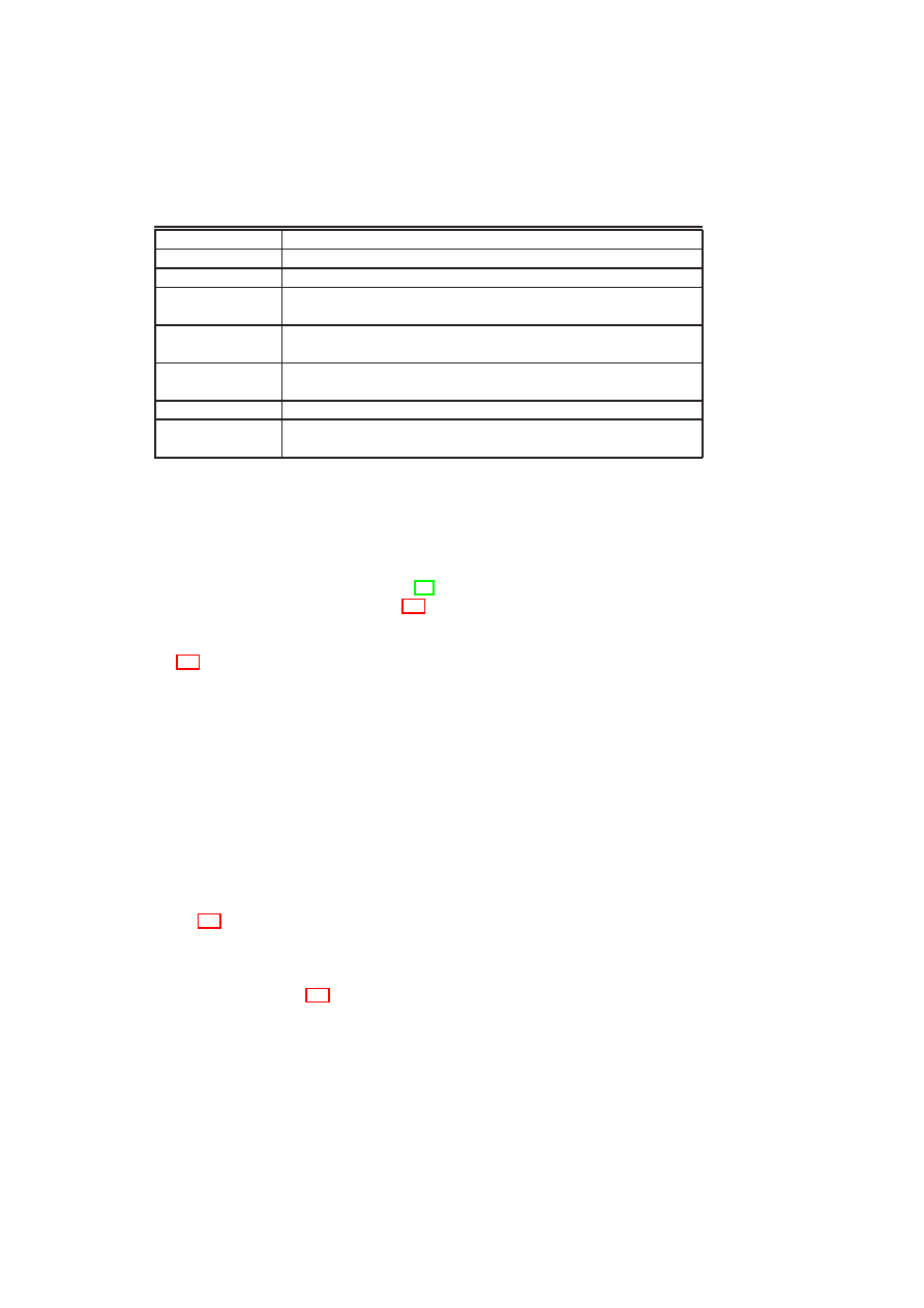
92
OpenTC D05.6 – Final Report of OpenTC Workpackage 5
Table 7.4: Examples of Security Properties used in Capability Modeling.
Property
Description
TVD Isolation
Flow control policies in place for a TVD.
Network
The actual topology of a virtual network in a physical machine.
Network Policy
Security policies for the network, such as firewall rules and isolation
rules stating which subnets can be connected.
Storage Policy
Policies for storage security, such as whether the disks are encrypted and
what VMs have permission to mount a particular disk.
Virtual Machines
The life-cycle protection mechanisms of the individual VMs, e.g., pre-
conditions for execution of a VM.
Hypervisor
Binary integrity of the hypervisor.
Users
The roles and associated users of a machine, e.g., who can assume the
role of administrator of the TVD master.
components according to TVD policy.
7.6
Implementation in Xen
In this section, we describe a Xen-based [11] prototype implementation of our secure
virtual networking framework. Figure 7.6 shows the implementation of two TVDs,
T V D
α
and
T V D
β
. The policy engine, also shown in the figure, implements the poli-
cies corresponding to the TVDs specified in the information flow control matrix of Fig-
ure 7.2, i.e., open connection within each TVD and closed connection between
T V D
α
and
T V D
β
.
7.6.1
Implementation Details
Our implementation is based on Xen-unstable 3.0.4, a VMM for the IA32 platform,
with the VMs running the Linux 2.6.18 operating system. Our networking extensions
are implemented as kernel modules in Dom0, which also acts as driver domain for the
physical NIC(s) of each physical host. A driver domain is special in the sense that it
has access to portions of the host’s physical hardware, such as a physical NIC.
The virtual network interface organization of Xen splits a NIC driver into two parts:
a front-end driver and a back-end driver. A front-end driver is a special NIC driver that
resides within the kernel of the guest OS. It is responsible for allocating a network
device within the guest kernel (eth0 in Dom1 and Dom2 of hosts A and B, shown in
Figure 7.6). The guest kernel layers its IP stack on top of that device as if it had a real
Ethernet device driver to talk to. The back-end portion of the network driver resides
within the kernel of a separate driver domain (Dom0 in our implementation) and creates
a network device within the driver domain for every front-end device in a guest domain
that gets created. Figure 7.6 shows two of these back-end devices, vif1.0 and vif2.0, in
each of the two hosts A and B. These back-end devices correspond to the eth0 devices
in Dom1 and Dom2, respectively, in each host.
Conceptually, the pair of front-end and back-end devices behaves as follows. Pack-
ets sent out by the network stack running on top of the front-end network device in the
guest domain appear as packets received by the back-end network device in the driver
domain. Similarly, packets sent out by the back-end network-device by the driver do-
OpenTC Document D05.6/V01 – Final R7628/2009/01/15/OpenTC Public (PU)

CHAPTER 7. SECURE VIRTUALIZED NETWORKING
93
Table 7.5: Assurance for Past, Present, and Future States used in Capability Modeling.
Past State
Description
Trust
A user believes that an entity has certain security properties.
Mutable Log
The entity provides log-file evidence (e.g., audits) that indicates that the
platform provides certain properties.
Immutable Logs
The entity has immutable logging systems (e.g., a TPM-quote [120]) for
providing evidence. Since the log cannot modified by the entity itself,
the resulting assurance is stronger than when mutable logs are used.
Present State
Description
Evaluations
Evaluation of a given state, e.g., Common Criteria evaluations [25].
Introspection
Introspection of a system by executing security tests, e.g., virus scanner.
Future State
Description
Policies
By providing policies and evidence of their enforcement, a system can
justify claims about its future behavior. e.g., DRM policies and VM life-
cycle protection policy.
Audit
By guaranteeing regular audits, organizations can claim that certain poli-
cies will be enforced in the future.
main appear to the network stack running within a guest domain as packets received by
the front-end network device. In its standard configuration, Xen is configured to simply
bridge the driver domain back-end devices onto the real physical NIC. By this mech-
anism, packets generated by a guest domain find their way onto the physical network
and packets on the physical network can be received by the guest domain.
The Xen configuration file is used to specify the particular vSwitch and the partic-
ular port in the vSwitch to which a Xen back-end device is attached. We use additional
scripts to specify whether a particular vSwitch should use one or both of VLAN tagging
and encapsulation mechanisms for isolating separate virtual networks.
The vSwitches for
T V D
α
and
T V D
β
are each implemented in a distributed fash-
ion (i.e., spread across hosts A and B) by a kernel module in Dom0, which maintains a
table mapping virtual network devices to ports on a particular vSwitch. Essentially, the
kernel module implements EtherIP processing for packets coming out of and destined
for the VMs. Each virtual switch (and hence VLAN segment) has a number identi-
fier associated with it. The Ethernet packets sent by a VM are captured by the kernel
module implementing part of the vSwitch as they are received on the corresponding
back-end device in Dom0. The packets are encapsulated using EtherIP with the net-
work identifier field set to match the identifier of the vSwitch that the VM is supposed
to be plugged into. The EtherIP packet is given either a multicast or unicast IP address
and simply fed into the Dom0 IP stack for routing onto the physical network. The
kernel module also receives EtherIP packets destined for the physical host. The mod-
ule un-encapsulates the Ethernet frames contained in the encapsulated EtherIP packets
and transmits the raw frame over the appropriate virtual network interface so that it is
received by the intended guest vNIC.
In addition to the kernel module for EtherIP processing, we have also implemented
a kernel module for VLAN tagging in Dom0 of each virtualized host. Ethernet pack-
ets sent by a VM are grabbed at the same point in the Dom0 network stack as in the
case of EtherIP processing. However, instead of wrapping the Ethernet packets in
an IP packet, the VLAN tagging module re-transmits the packets unmodified into a
OpenTC Document D05.6/V01 – Final R7628/2009/01/15/OpenTC Public (PU)
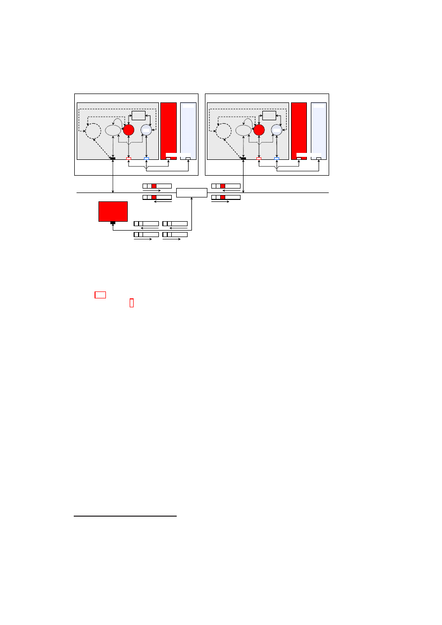
94
OpenTC D05.6 – Final Report of OpenTC Workpackage 5
Host A
Dom 1
Dom 0
α
encap.
module
VLAN
tagging
module
Policy
Engine
vSwitches
eth0
eth0
vif2.0
vif1.0
eth0
front-end devices
back-end
devices
physical
NIC
VLAN-capable
physical switch
Host B
Dom 1
Dom 0
α
encap.
module
VLAN
tagging
module
Policy
Engine
vSwitches
eth0
eth0
vif2.0
vif1.0
eth0
front-end devices
back-end
devices
physical
NIC
Host C
eth0
physical NIC
(VLAN un-aware)
C
A1
C
B1
C
A1
C
B1
A1
C
B1
C
A1
C
B1
C
Dom 2
Dom 2
β
β
Figure 7.6: Prototype Implementation of TVDs.
pre-configured Linux VLAN device (eth0.
α
and eth0.
β
of hosts A and B, shown in
Figure 7.6) matching the VLAN that the VM’s vNIC is supposed to be connected to.
The VLAN device
5
(provided by the standard Linux kernel VLAN support) applies
the right VLAN tag to the packet before sending it out onto the physical wire through
the physical NIC. The VLAN tagging module also intercepts VLAN packets arriving
on the physical wire destined for a VM. The module uses the standard Linux VLAN
Ethernet packet handler provided by the 8021q.ko kernel module with a slight modifi-
cation: the handler removes the VLAN tags and, based on the tag, maps packets to the
appropriate vSwitch (
α
or
β
) which, in turn, maps them to the corresponding back-end
device (vif1.0 or vif2.0) in Dom0. The packets eventually arrive at the corresponding
front-end device (eth0 in Dom1 or Dom2) as plain Ethernet packets.
7.6.2
Implementation Issues
Below are some implementation issues we had to tackle in realizing the VLAN and
encapsulation approaches.
(1) Some Ethernet cards offer VLAN tag filtering and tag removal/offload capa-
bilities. Such capabilities are useful when running just a single kernel on a physical
platform, in which case there is no need to maintain the tags for making propagation
decisions. However, for our virtual networking extensions, the hardware device should
not strip the tags from packets on reception over the physical wire; instead, the ker-
nel modules we have implemented should decide to which VM the packets should be
forwarded. For this purpose, we modified the Linux kernel tg3.ko and forcedeth.ko
network drivers so as to disable VLAN offloading.
(2) For efficiency reasons, the Xen front-end and back-end driver implementations
avoid computing checksums between them for TCP/IP and UDP/IP packets. We mod-
5
An alternative approach, which we will implement in the future, is to directly tag the packet and send
the tagged packet straight out of the physical NIC without relying on the standard Linux VLAN devices.
OpenTC Document D05.6/V01 – Final R7628/2009/01/15/OpenTC Public (PU)

CHAPTER 7. SECURE VIRTUALIZED NETWORKING
95
ified the Xen code to also handle our EtherIP-encapsulated IP packets in a similar
manner.
(3) The EtherIP encapsulation approach relies on mapping a virtual Ethernet broad-
cast domain to a IP multicast domain. While this works in a LAN environment, we en-
countered problems when creating VLAN segments that span WAN-separated physical
machines. We resolved this issue by building uni-directional multicast tunnels between
successive LAN segments.
7.7
Discussion
In this paper, we introduced a secure virtual networking model and a framework for
efficient and security-enhanced network virtualization. The key drivers of our frame-
work design were the security and management objectives of virtualized data centers,
which are meant to co-host IT infrastructures belonging to multiple departments of an
organization or even multiple organizations.
Our framework utilizes a combination of existing networking technologies (such
as Ethernet encapsulation, VLAN tagging, VPN, and NAC) and security policy en-
forcement to concretely realize the abstraction of Trusted Virtual Domains, which can
be thought of as security-enhanced variants of virtualized network zones. Policies are
specified and enforced at the intra-TVD level (e.g., membership requirements) and
inter-TVD level (e.g., information flow control).
Observing that manual configuration of virtual networks is usually error-prone, our
design is oriented towards automation. To orchestrate the TVD configuration and de-
ployment process, we introduced management entities called TVD masters. Based on
the capability models of the physical infrastructure that are given as input to them,
the TVD masters coordinate the set-up and population of TVDs using a well-defined
protocol.
We described a Xen-based prototype that implements a subset of our secure net-
work virtualization framework design. The performance of our virtual networking ex-
tensions is comparable to the standard Xen (bridge) configuration.
OpenTC Document D05.6/V01 – Final R7628/2009/01/15/OpenTC Public (PU)

Chapter 8
Public Key Infrastructure
P. Lipp, M. Pirker (IAIK), G. Ramunno, D. Vernizzi (POL)
8.1
Introduction
This chapter outlines a basic design for integration of Trusted Computing (TC) features
into a Public-Key Infrastructure (PKI). The adoption of Trusted Computing technolo-
gies demands an enhancement of existing infrastructures as well as an adaption of
procedures within PKIs. One can identify multiple areas where new development for
Trusted Computing is needed:
•
First, the design of a trusted platform agent (TPA). Its task is to support initial-
ising, activating and deactivating the TPM security chain under user control. It
supports the most important mechanisms and services for creation (or request
creation) of keys and credentials related to Trusted Computing. It is capable of
communicating with network PKI services.
•
Further, a so called “Privacy CA”, an entity offering PKI operations (certificate
issuance, validation, . . . ) just like traditional certification authority services, but
specialising in Trusted Computing specific tasks. This includes the handling of
the TPM Attestation Identity Key credential creation cycle and managing asso-
ciated request/response messages, keys and credentials. Also, offering services
for determination of current status and possible re-evaluation of credentials.
•
As a communication protocol between local services (TPA) and network service
(privacy CA) the XML Key Management Protocol [129] is employed. It offers
functionality to transport traditional PKI operations and enough flexibility for
new Trusted Computing specific operations.
•
Advanced services are out of scope of this document, only basic services are
covered here. The implementation experience of the basic services will lead
to a refinement of the services design. Additional services are, e.g., the inte-
gration of Subject Key Attestation Evidence (SKAE) extension support, Direct
Anonymous Attestation (DAA) as a replacement concept for the privacy CA, and
automated policy checking plus validation support. Further, once the XKMS im-
plementation reaches a stable state, an alternative communication protocol will
be researched.
96

CHAPTER 8. PUBLIC KEY INFRASTRUCTURE
97
8.2
Basic Trusted Computing PKI
A public key infrastructure is a framework enabling authentication, confidentiality and
integrity services using public key cryptography. It helps the users of a (public) network
to, e.g., authenticate the identity of communication partners and thus establish levels
of trust and/or secure communication channels.
The Trusted Computing concept introduces new types of security credentials and
procedures. Some fit established structures, some require small adoptions and some
represent new concepts.
Associated with the credentials is a life cycle of introducing them to the infrastruc-
ture, exchange of information between nodes in the network, (re)validation/evaluation
of their information value and finally withdrawal from use.
The new components of a basic Trusting Computing PKI are discussed in the fol-
lowing sections.
8.2.1
EK Certificate
Every Trusted Platform Module (TPM) is (should be) accompanied by a corresponding
TPM Endorsement certificate. This certificate contains the public part of the Endorse-
ment Key (EK) pair, which can be viewed as a TPM identity. The private part, called
the private Endorsement Key, is stored permanently inside the TPM and can not be re-
trieved once inserted. The certificate is (typically) signed by the TPM manufacturer and
represents an assertion that the specific TPM conforms with the required specifications
and the private Endorsement Key is kept safe by a TPM.
Extraction
As per [116] specification a distinct location of non-volatile RAM on the TPM chip
is reserved for the TPM EK certificate. Further, the TPM commands to extract non-
volatile memory content from the TPM are standardised. Thus, an obvious function of
the TPA is to extract the EK certificate. Unfortunately, to this date the only manufac-
turer to include a TPM EK certificate on chip in every shipped TPM is Infineon.
Creation
If a TPM is shipped without a manufacturer issued certificate, a “late” construction of
an EK certificate may be applicable in selected scenarios, e.g., a limited deployment
in a department wide setup. Tools for creation of an EK certificate, utilising the real
public Endorsement Key of a TPM, are already available from OpenTC partner IAIK.
Integration of this functionality into a TPA is aimed for.
Who signs the TPM EK certificate and thus vouches for its integrity is of crucial
importance. In a limited deployment scenario a centralised entity can issue homegrown
EK certificates as well as offer services for their validation.
OpenTC Document D05.6/V01 – Final R7628/2009/01/15/OpenTC Public (PU)

98
OpenTC D05.6 – Final Report of OpenTC Workpackage 5
In the case of TPM vendor Infineon the necessary certificate chain for validation is
freely available for download from the manufacturers homepage. In the case of a self
made certificate, the signing authority certificate must be made available and accessible
to a validation entity later.
Note that a proof of possession of an EK private key can only be done with a full
AIK cycle (see section 8.2.3). This is an intentional limit of the TPM design.
Note also that a TPM EK certificate is the only proof that the corresponding public
Endorsement Key actually belongs to a specific type of TPM. Only a certificate signed
by a manufacturer (or equivalent important entity) is proof that the referenced TPM is a
hardware TPM. Self created certificates may contain an EK public key which actually
belongs to a TPM software emulator (e.g.,
http://tpm-emulator.berlios.
de/
)
Validation
Validation of an TPM EK certificate may be accomplished in multiple steps:
•
A local user can read the public EK key from the local TPM and compare it to the
one contained in the sample TPM EK certificate. Upon match, one can assume
the certificate belongs to the TPM in the local machine.
•
If the issuer certificate chain is locally available and the Trusted Platform Agent
contains the necessary cryptographic support, a cryptographic validation of the
signatures of the certificate chain is possible.
•
A thin TPA with minimal footprint may offload certificate verification to a remote
service with more resources. In this design the usage of XKMS is suggested (see
section 8.4.4).
Note that the “how” is not as important as the security implications of remote
verification. The EK uniquely identifies the TPM, thus, every operation showing
the EK to third parties must ensure that the third party can be trusted. Also,
security of the communication link with the remote service has to be considered.
•
Full validation also requires a check with a PKI of the manufacturer of the spe-
cific TPM model (or series), if there are any known conditions affecting the
security of the TPM. This infrastructure is out of scope for a basic infrastructure.
Revocation checking is not part of the Basic PKI.
8.2.2
Platform Certificate
The platform manufacturer vouches for the parts of a platform with a Platform Endorse-
ment (PE) Credential. It represents an assertion that the specific platform incorporates
a properly certified TPM and the necessary infrastructure according to TCG specifi-
cations. There is a requirement for a “root of trust” (CRTM) to be a starting point for
building a “chain of trust” and related security measurements are implemented to check
the integrity of the platform.
So far no PE certificate is known to have been regularly shipped with a platform.
However, a tool to create PE certificates is available from OpenTC partner IAIK. As the
OpenTC Document D05.6/V01 – Final R7628/2009/01/15/OpenTC Public (PU)

CHAPTER 8. PUBLIC KEY INFRASTRUCTURE
99
PE certificate is primarily part of the AIK cycle (see section 8.2.3) to be implemented
for the basic PKI, the creation of a fake PE certificate with “random” values is aimed
for as proof of concept.
8.2.3
Attestation Identity
As the Endorsement Key uniquely identifies a TPM and hence a specific piece of sur-
rounding hardware, the privacy of the user(s) is at risk if the EK is used directly for
transactions. As a consequence, the TCG introduced Attestation Identity Keys (AIKs)
and associated AIK certificates (standard X509 Public Key Certificates that include ex-
tensions defined by TCG), which cannot be backtracked directly to a specific platform.
The only entity that possibly knows more details is a trusted third party that issues the
AIK certificates, the so called Privacy CA.
AIK certificate creation cycle
In order to create an AIK certificate the following steps are taken:
•
The Trusted Platform Agent (TPA, see section 8.3) running on a machine con-
taining a TPM, calls the
CollateIdentityRequest
function of the Trusted Software
Stack (TSS) layer.
•
This creates an Attestation Identity RSA key pair and a certification request in-
tended for the Privacy CA.
•
The request is transported to the Privacy CA, using proper PKI operational pro-
tocols.
•
The Privacy CA validates the request content (and included EK and PE certifi-
cates). On success it issues an AIK certificate, encrypted with the public EK key
of the TPM and thus only readable by the indented recipient.
•
The Privacy CA result is communicated back to the TPA.
•
The TPA calls the
ActivateIdentity
function of the Trusted Software Stack, thus
unwrapping the AIK certificate.
•
The TPA stores the AIK certificate locally.
Summarising, an activated AIK identity comprises a) an “identity” TPM keypair and
b) an associated certificate proving that the keypair belongs to a “valid” TPM, vouched
for by a Privacy CA entity.
Privacy CA
The role of the Privacy CA (PCA) is of being a trusted third party that works as an
anonymiser. For privacy reasons the unique TPM Endorsement Key should only be
shown on a “need to know basis”. In the concept of the AIK cycle (see previous
section) the Privacy CA issues AIK certificates for a “derived” AIK key. This ensures
OpenTC Document D05.6/V01 – Final R7628/2009/01/15/OpenTC Public (PU)

100
OpenTC D05.6 – Final Report of OpenTC Workpackage 5
better anonymity of the EK key holder, but still contains proof of the underlying Trusted
Computing supported hardware.
Operation of a Privacy CA is guided by a published policy. It should clearly de-
scribe how the relationship EK certificate versus issued AIK certificates is managed.
The implementation options for a Privacy CA cover a spectrum from “remember every-
thing” to “know enough for the specific operation, forget everything after completion
of operation”. Thus, the usage of a specific PCA may be usage scenario dependent.
Implementation of a Privacy CA covers functionality for
•
A network front end for receiving/sending requests/responses. The design in this
document uses the XML Key Management Standard (XKMS).
•
A unit implementing the AIK cycle.
•
Local storage. The PCA handles multiple types of certificates. It receives Trusted
Computing specific certificates (EK, etc.), it issues AIK certificates and needs
foreign certificates for validation (e.g., EK manufacturer certificate chain). The
storage must accommodate multiple types.
•
A validation unit, capable of determining the status of certificates.
In the easiest scenario the validation concerns self issued certificates, thus trans-
forming a validation operation to a simple signature check or lookup in local
storage. Further, the validation unit should be preloaded with manufacturer cer-
tificate chains (e.g., those already available from Infineon), if possible, too.
The more complex case of actively contacting external entities for missing pieces
required for validation is out of scope for a basic PKI.
8.3
Trusted Platform Agent
A PKI requires both server side components, such as certificate authorities, as well as
client side applications that provide access to PKI services. In the context of Trusted
Computing such a client application is referred to as the Trusted Platform Agent (TPA).
For wide user acceptance it is crucial that the TPA makes all Trusted Computing re-
lated functionality available in a consistent and user-friendly way. Ideally, the TPA
is designed and implemented in a modular way that provides an easy integration of
additional advanced services later on. Furthermore, in terms of user friendliness the
TPA is expected to provide an abstraction of the underlying system concepts that is
understandable and manageable for an average user: for this purpose a simple API is
provided as well as console commands running on top of it. The TPA largely relies
on the services provided by the TSS stack. The overall architecture design of the TPA
and the individual system layers is presented in Figure 8.1. Dark grey boxes represent
components that will be possibly developed for the Advanced PKI.
The initial basic core functionalities provided by TPA fall in the following cate-
gories:
•
TPM and platform management. This category includes operations such as
TakeOwnership
, enabling and disabling the TPM and reading TPM status in-
formation.
OpenTC Document D05.6/V01 – Final R7628/2009/01/15/OpenTC Public (PU)
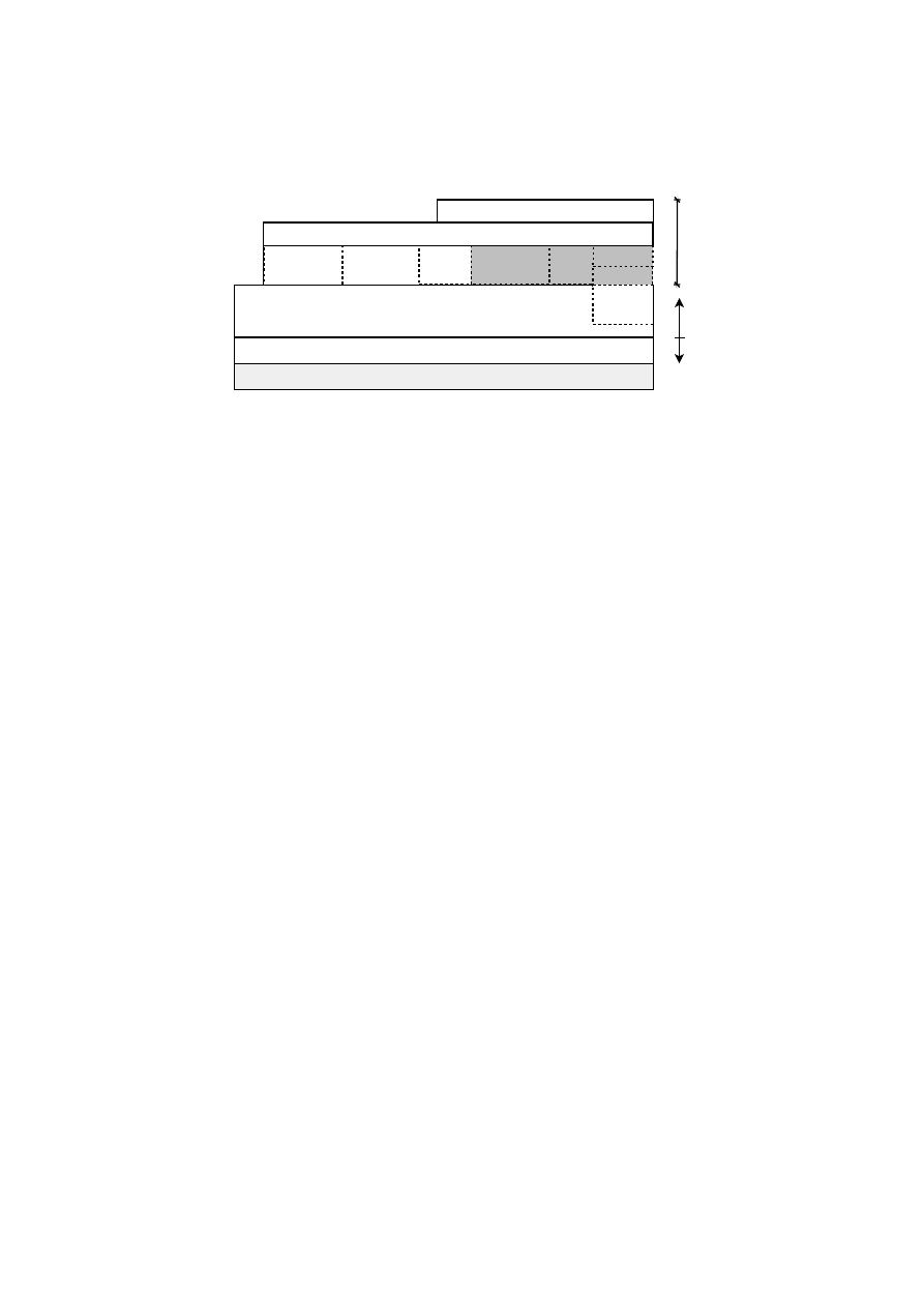
CHAPTER 8. PUBLIC KEY INFRASTRUCTURE
101
(hardware or software) TPM
TPM Device Driver
TSS Stack
SKAE
parser
DAA
wrapper
TPM
management
and reporting
CA and PCA
interface
Other service
modules
DAA
functions
User space
Kernel space
DAA
platform role
Local
storage
TPA console utilities
TPA API
Trusted Platform
Agent (TPA)
Figure 8.1: Trusted Platform Agent (TPA) and underlying layers
•
TC credentials management. This category includes operations needed to man-
age the life cycle of TC credentials (EK, PE, and AIK certificates) by interacting
with TC-enabled authorities. The TPA and the latter communicate through net-
work protocols, XKMS will be used for the first prototype (required extensions
will be developed as needed)
– EK certificate: extraction, creation, validation
– Platform certificate: creation, validation
– AIK certificate: creation, validation, reissue, revocation
•
Light support for standard X.509 credentials. A simplified support to request a
standard X.509 certificate is provided: it is possible to manage certificate with
standard profiles using the TC-enabled PKI. This support does not include the
interaction with standard PKI authorities; however the interoperability of the
issued certificates with existing standard PKIs is guaranteed.
•
Local storage for TC-related and standard keys and certificates
•
Integrity measurement and reporting. This category includes the following TPM
operations: extending PCRs, reading PCRs, activating identities (i.e., AIK cer-
tificates) and TPM quote operation.
•
API to access all functionalities provided by TPA.
In addition, the TPA can also act as an integration point for a number of other services in
the context of Trusted Computing. The main benefit of this approach for the user is that
all Trusted Computing related tasks can be done from a single point, the TPA. Adding
additional services is facilitated by the modular nature of the TPA. These additional
services might include (but are not limited to):
•
Management of the DAA communications among the different roles (Trusted
Platform, Issuer and Verifier)
– Standard formats for the exchanged DAA data and messages for using
DAA as a standalone protocol or integrated within other protocols
– A network protocol for using the DAA as a standalone application protocol
OpenTC Document D05.6/V01 – Final R7628/2009/01/15/OpenTC Public (PU)

102
OpenTC D05.6 – Final Report of OpenTC Workpackage 5
•
Support for another TC-PKI operational protocol like Certificate Management
Messages over CMS (CMC) [51] in addition to XKMS.
•
Support for the Subject Key Attestation Evidence (SKAE) extension for X.509
credentials.
•
A front end for key backup and key migration.
•
A user and policy management framework.
8.4
XKMS mapping
A public key infrastructure integrates multiple actors – clients, certification authorities
and specialised services. Over the years multiple protocols were developed in the area
of PKI and credential management. For Trusted Computing it is necessary to carry
traditional PKI services as well as TC specific attributes, queries and data blobs.
XML Key Management Services (XKMS) [129]) is chosen for a first basic Trusted
Computing enabled PKI setup, which is in line with the considerations of the TCG in
[111] (chap. 6.5.2/p.43) and their recommendation:
“XKMS provides a way to express certificate management function in XML, while
providing a wrapper over legacy CA services designed for X.509 certificates. As such,
XKMS provides the most attractive solution for credential management for existing
CAs in the PKI industry.”
XKMS supports four standard registration service functions: Register, Recover,
Reissue and Revoke. These offer a wide range of parameters and thus cover the whole
life cycle support of credentials.
Further, two key information service functions, Locate and Validate, provide search
and status query functionality about credentials deployed in the PKI.
Considering the PKI components outlined in section 8.2 and 8.3, in the following
sections a mapping of PKI operations to XKMS specific requests and responses is
established and interaction with Trusted Computing usage discussed.
8.4.1
Message Structure
XKMS is an XML based protocol for common PKI operations. The revised edition 2.0
of XKMS [129] reached recommendation status in June 2005. In order to reduce du-
plicate descriptions in the following sections, the common XML structures of a typical
XKMS request and response message are discussed.
Request
The following block outlines the structure of a typical XKMS request:
< ? xml v e r s i o n =
" 1 . 0 "
e n c o d i n g =
"UTF
−
8"
? >
< . . . R e q u e s t x m l n s=
" h t t p : / / www . w3 . o r g / 2 0 0 2 / 0 3 / xkms # "
x m l n s : d s =
" h t t p : / / www . w3 . o r g / 2 0 0 0 / 0 9 / x m l d s i g # "
x m l n s : x e n c =
" h t t p : / / www . w3 . o r g / 2 0 0 1 / 0 4 / x m l e n c # "
OpenTC Document D05.6/V01 – Final R7628/2009/01/15/OpenTC Public (PU)

CHAPTER 8. PUBLIC KEY INFRASTRUCTURE
103
I d =
" . . . "
S e r v i c e =
" h t t p : / / o p e n t c . i a i k . t u g r a z . a t / xkms / . . . "
>
. . . p a y l o a d . . .
< A u t h e n t i c a t i o n >
. . .
< / A u t h e n t i c a t i o n >
< / . . . R e q u e s t >
The XML tag name of an XKMS request message always ends in
Request
. Exam-
ple tag names are
LocateRequest
,
ValidateRequest
, etc. The XKMS XML
schema includes the schemata of the XML digital signature standard [130] as well
as the XML encryption standard [131]. A good solution is to assign the default XML
namespace to XKMS and assign easy recognisable prefixes for the inclusions, as shown
above.
Every XKMS message must carry a unique
Id
identifier generated by the originator
of the message. Typically this is a random string of at minimum 32 characters (to
provide sufficient entropy against attacks).
The
Service
attribute contains the URI of the network service endpoint. For a
basic PKI infrastructure the HTTP protocol is sufficient as transport medium. Thus, a
XKMS request is mapped to a HTTP POST operation:
POST / xkms / . . . HTTP / 1 . 0
C o n t e n t
−
T y p e : t e x t / xml
H o s t : o p e n t c . i a i k . t u g r a z . a t
C o n n e c t i o n : C l o s e
Cache
−
C o n t r o l : no
−
c a c h e
C o n t e n t
−
L e n g t h :
. . .
<? xml v e r s i o n =
" 1 . 0 "
e n c o d i n g =
"UTF
−
8"
? >
< . . . R e q u e s t
. . . . .
>
The path component “
/xkms/...
” is used to distinguish categories of
requests. An obvious mapping would be, e.g., “
.../aik
” for all AIK specific
requests and “
.../ek
” for EK related operations. Implementation experience is ex-
pected to define useful groupings.
An optional
Authentication
component is employed for operations which
are restricted to specific clients or need proof of knowledge of a shared secret. The
XKMS standard contains a description of an algorithm to derive a cryptographic
key from a secret string (e.g., password). One can then use this key to generate
a XML digital signature inside the
Authentication
message component which
references the
KeyBinding
type payload of the request. If the validation of the
Authentication
element fails at server side, the response message contains
“
ResultMajor=Sender
” with “
ResultMinor=NoAuthentication
”.
Response
The following block outlines the structure of a typical XKMS response:
<? xml v e r s i o n =
" 1 . 0 "
e n c o d i n g =
"UTF
−
8"
? >
OpenTC Document D05.6/V01 – Final R7628/2009/01/15/OpenTC Public (PU)

104
OpenTC D05.6 – Final Report of OpenTC Workpackage 5
< . . . R e s u l t x m l n s=
" h t t p : / / www . w3 . o r g / 2 0 0 2 / 0 3 / xkms # "
x m l n s : d s =
" h t t p : / / www . w3 . o r g / 2 0 0 0 / 0 9 / x m l d s i g # "
x m l n s : x e n c =
" h t t p : / / www . w3 . o r g / 2 0 0 1 / 0 4 / x m l e n c # "
I d =
" . . . "
R e q u e s t I d =
" . . . "
R e s u l t M a j o r =
" h t t p : / / www . w3 . o r g / 2 0 0 2 / 0 3 / xkms # S u c c e s s "
R e s u l t M i n o r =
" h t t p : / / www . w3 . o r g / 2 0 0 2 / 0 3 / xkms # . . . "
S e r v i c e =
" h t t p : / / o p e n t c . i a i k . t u g r a z . a t / xkms / . . . "
>
< S i g n a t u r e x m l n s=
" h t t p : / / www . w3 . o r g / 2 0 0 0 / 0 9 / x m l d s i g # "
>
. . . g l o b a l m e s s a g e
s i g n a t u r e
o f XKMS r e s p o n d e r . . .
< / S i g n a t u r e >
. . . p a y l o a d . . .
< / . . . R e s u l t >
The XML tag name of an XKMS response message always ends in
Result
. Example
tag names are
LocateResult
,
ValidateResult
, etc. Note that there also exists
a basic
Result
response message. This one is emitted by the server when he cannot
properly parse an invalid request and thus cannot determine the more specific type of a
request.
In comparison to the XKMS request message the result message contains additional
components:
•
RequestId
is a copy of the
Id
of the corresponding request message. It en-
ables a client with multiple XKMS messages in transit to match request-response
pairs.
•
ResultMajor
specifies the overall outcome of the request. In case of process-
ing of the request without failure a
Success
result is expected. In the case of
an error
ResultMajor
contains an indication who is assumed to be the cause
of the error,
Sender
or
Receiver
.
•
An optional
ResultMinor
specifies additional details of the result status of a
request, if the value in
ResultMajor
can not alone represent all interesting
information.
A response by an XKMS service is expected to be always signed. This XML digital
signature encloses the whole XKMS message. In order for the client to verify the sig-
nature, the public key of the XKMS service must be known on the client side. Typically
the public key is shipped to the client in form of a X509 type certificate.
The result received from an XKMS request submitted using HTTP POST typically
looks like:
HTTP / 1 . 1 200 OK
D a t e :
. . . . .
C o n t e n t
−
T y p e : t e x t / xml ;
c h a r s e t =UTF
−
8
C o n t e n t
−
L e n g t h :
. . .
C o n n e c t i o n : c l o s e
< ? xml v e r s i o n =
" 1 . 0 "
e n c o d i n g =
"UTF
−
8"
? >
< . . . R e s u l t
. . . . .
OpenTC Document D05.6/V01 – Final R7628/2009/01/15/OpenTC Public (PU)

CHAPTER 8. PUBLIC KEY INFRASTRUCTURE
105
8.4.2
RegisterRequest
A XKMS RegisterRequest is used to build a binding of information, typically to a
public key(pair). The registration request message contains a prototype of the requested
binding.
In the context of Trusted Computing a RegisterRequest may perform the following
functions:
Creation of an EK certificate
The TCG infrastructure concept requires the public endorsement key of a TPM accom-
panied by a certificate. To integrate TPMs (or TPM emulators) without a certificate, a
function to create one from a public key is desired.
Structure of a request, including a RSA public key:
< R e g i s t e r R e q u e s t
. . . >
< P r o t o t y p e K e y B i n d i n g I d =
" . . . . . "
>
< Key Info
. . . >
<KeyValue >
<RSAKeyValue>
<Modulus > . . . < / Modulus >
<Exponent > . . . < / Exponent >
< / RSAKeyValue>
< / KeyValue >
< / Key Info >
< / P r o t o t y p e K e y B i n d i n g>
< A u t h e n t i c a t i o n >
. . . S i g n a t u r e
r e f e r e n c i n g P r o t o t y p e K e y B i n d i n g . . .
< / A u t h e n t i c a t i o n >
< / R e g i s t e r R e q u e s t >
Creation of an AIK identity
The exchange between a client system TPM/TSS and a Privacy CA to create an AIK
certificate is almost fully standardised in the TCG specifications. Basically, it com-
prises a transfer of an encrypted binary blob (namely an array of bytes) to the Privacy
CA, resulting in 2 binary blobs as an answer. Unfortunately the features of the XKMS
protocol do not allow for an obvious mapping. To prevent early modification of XKMS
we decide to transfer the blob information in this case in the
OpaqueClientData
tag. As the name suggests the content of this tag should be opaque to the server, how-
ever the gain of experience of getting a running prototype faster has priority. In a later
implementation of an advanced PKI the use of, e.g., the XKMS MessageExtension
feature for a cleaner solution may be considered.
Structure of the request:
< R e g i s t e r R e q u e s t
. . . >
< P r o t o t y p e K e y B i n d i n g I d =
" . . . . . "
>
< Key Info
. . . >
OpenTC Document D05.6/V01 – Final R7628/2009/01/15/OpenTC Public (PU)

106
OpenTC D05.6 – Final Report of OpenTC Workpackage 5
<KeyValue >
<RSAKeyValue>
<Modulus > . . . < / Modulus >
<Exponent > . . . < / Exponent >
< / RSAKeyValue>
< / KeyValue >
< / Key Info >
< / P r o t o t y p e K e y B i n d i n g>
< A u t h e n t i c a t i o n >
. . . S i g n a t u r e
r e f e r e n c i n g P r o t o t y p e K e y B i n d i n g . . .
< / A u t h e n t i c a t i o n >
< / R e g i s t e r R e q u e s t >
The
blob
element
containing
the
binary
blob
as
returned
by
the
CollateIdentityRequest
function of the TSS.
Structure of the response:
< R e g i s t e r R e s u l t
. . . >
< S i g n a t u r e > . . . < / S i g n a t u r e >
< Key Binding>
< Key Info
. . . >
<X509Data>
< X 5 0 9 C e r t i f i c a t e> . . . < / X 5 0 9 C e r t i f i c a t e>
< / X509Data>
< / Key Info >
< S t a t u s S t a t u s V a l u e =
" h t t p : / / www . w3 . o r g / 2 0 0 2 / 0 3 / xkms # V a l i d "
/ >
< / Key Binding>
< / R e g i s t e r R e s u l t >
With
blob1
containing
the
symCaAttestation
and
blob2
the
asymCaContents
answer of the Privacy CA, to be passed to the
ActivateIdentity
function of the client TSS.
For a discussion of other
Authentication
possibilities, see also section 8.4.5.
8.4.3
LocateRequest
A XKMS LocateRequest provides a discovery function. It resolves the passed query
keybinding and matches request information with local and/or remote data. The answer
of a Locate service makes no assertions to any validation criteria. However, a result of
a Locate service may be forwarded to a validation service, or, if possible, additional
trust verification is done locally.
The following services are useful in a Trusted Computing context:
Query for an AIK certificate
AIK certificates do not contain a subject distinguished name of the certificate owner,
but only a
label
, chosen freely at AIK certificate creation time by the client/user. To
retrieve a specific AIK certificate a locate request for a specific label name is desired.
OpenTC Document D05.6/V01 – Final R7628/2009/01/15/OpenTC Public (PU)

CHAPTER 8. PUBLIC KEY INFRASTRUCTURE
107
An obvious mapping to XKMS would be to use the
X509SubjectName
in the
KeyInfo
portion, however, as some XKMS libraries may check this field strictly for
X509 name rules compatibility (and the AIK label specification is less restrictive) this
is avoided and the
KeyName
field used instead.
Thus, a query for a specific AIK certificate looks like:
< L o c a t e R e q u e s t
. . . >
<RespondWith> h t t p : / / www . w3 . o r g / 2 0 0 2 / 0 3 / xkms# X 5 0 9 C e r t < / RespondWith>
<QueryKeyBinding >
< Key Info
. . . >
<KeyName> l a b e l O f A i k C e r t i f i c a t e < / KeyName>
< / Key Info >
< / QueryKeyBinding >
< / L o c a t e R e q u e s t>
An answer is of the form:
< L o c a t e R e s u l t
. . .
R e s u l t M a j o r =
" h t t p : / / www . w3 . o r g / 2 0 0 2 / 0 3 / xkms # S u c c e s s "
. . . >
< S i g n a t u r e > . . . < / S i g n a t u r e >
< U n v e r i f i e d K e y B i n d i n g >
< Key Info
. . . >
<X509Data>
< X 5 0 9 C e r t i f i c a t e> . . . < / X 5 0 9 C e r t i f i c a t e>
< / X509Data>
< / Key Info >
< / U n v e r i f i e d K e y B i n d i n g >
< / L o c a t e R e s u l t >
Note that depending on the policy of the Privacy CA the AIK label may not be unique
and in the
X509Data
component multiple certificates may be returned.
8.4.4
ValidateRequest
The operations of an XKMS ValidateRequest are similar to a LocateRequest (see pre-
vious section), however, the returned status of a binding is evaluated from well defined
validation criteria. A validation service returns only information which has been vali-
dated by the service. Its validation policy is expected to be publicly available.
In order to validate a specific certificate, it is sent to the service:
< V a l i d a t e R e q u e s t
. . . >
<RespondWith>
h t t p : / / www . w3 . o r g / 2 0 0 2 / 0 3 / xkms# X5 0 9 Ch ain
< / RespondWith>
<QueryKeyBinding >
< Key Info
. . . >
<X509Data>
< X 5 0 9 C e r t i f i c a t e> . . . < / X 5 0 9 C e r t i f i c a t e>
< / X509Data>
OpenTC Document D05.6/V01 – Final R7628/2009/01/15/OpenTC Public (PU)

108
OpenTC D05.6 – Final Report of OpenTC Workpackage 5
< / Key Info >
< / QueryKeyBinding >
< / V a l i d a t e R e q u e s t >
The expected result upon positive validation is an
X509Chain
, a certificate chain
build from the supplied certificate to a trusted root.
< V a l i d a t e R e s u l t
. . .
R e s u l t M a j o r =
" h t t p : / / www . w3 . o r g / 2 0 0 2 / 0 3 / xkms # S u c c e s s "
. . . >
< S i g n a t u r e > . . . < / S i g n a t u r e >
< Key Binding>
< Key Info x m l n s=
" h t t p : / / www . w3 . o r g / 2 0 0 0 / 0 9 / x m l d s i g # "
>
<X509Data>
< X 5 0 9 C e r t i f i c a t e> . . . < / X 5 0 9 C e r t i f i c a t e>
< X 5 0 9 C e r t i f i c a t e> . . . < / X 5 0 9 C e r t i f i c a t e>
< X 5 0 9 C e r t i f i c a t e> . . . < / X 5 0 9 C e r t i f i c a t e>
< / X509Data>
< / Key Info >
< S t a t u s S t a t u s V a l u e =
" h t t p : / / www . w3 . o r g / 2 0 0 2 / 0 3 / xkms # V a l i d "
>
< V a l i d R e a s o n >
h t t p : / / www. w3 . o r g / 2 0 0 2 / 0 3 / xkms# I s s u e r T r u s t
< / V a l i d R e a s o n >
< V a l i d R e a s o n >
h t t p : / / www. w3 . o r g / 2 0 0 2 / 0 3 / xkms# S i g n a t u r e
< / V a l i d R e a s o n >
< V a l i d R e a s o n >
h t t p : / / www. w3 . o r g / 2 0 0 2 / 0 3 / xkms# V a l i d i t y I n t e r v a l
< / V a l i d R e a s o n >
< / S t a t u s >
< / Key Binding>
< / V a l i d a t e R e s u l t >
The corresponding result message contains the certificate chain as an array of certifi-
cates and a
Status
component describing more detailed evaluation results.
In Trusted Computing it is of interest to check the status of EK and AIK certificates.
For a basic PKI the XKMS validation message exchange is the same for both cases.
Note that a PE certificate is an attribute certificate whereas XKMS is designed for
X509 certificates. An attribute certificate may be included somehow in raw form as
array of bytes, but the feasibility of this concept still has to be determined.
Note that it is a policy decision of the service whether the service only validates
its own issued certificates or also uses external resources. E.g., validation of an EK
certificate may be done locally at the server if the certificate chain is known, however
proper validation should also include a revocation check with a manufacturer PKI, if
available.
8.4.5
RevokeRequest
An XKMS RevokeRequest manifests the desire to invalidate a previously issued bind-
ing. The payload consists of what to revoke, a certificate, etc.:
OpenTC Document D05.6/V01 – Final R7628/2009/01/15/OpenTC Public (PU)

CHAPTER 8. PUBLIC KEY INFRASTRUCTURE
109
<? xml v e r s i o n =
" 1 . 0 "
e n c o d i n g =
"UTF
−
8"
? >
< Rev o keRequest
. . . >
< RevokeKeyBinding I d =
" . . . "
>
< Key Info
. . . >
<X509Data>
< X 5 0 9 C e r t i f i c a t e> . . . < / X 5 0 9 C e r t i f i c a t e>
< / X509Data>
< / Key Info >
< S t a t u s
S t a t u s V a l u e =
" h t t p : / / www . w3 . o r g / 2 0 0 2 / 0 3 / xkms # I n d e t e r m i n a t e "
/ >
< / RevokeKeyBinding >
< A u t h e n t i c a t i o n >
. . . S i g n a t u r e
r e f e r e n c i n g R e v o k e K e y B i n d i n g . . .
< / A u t h e n t i c a t i o n >
< / Rev o keRequest >
It is expected that this function is always restricted to a specific client population, thus
always requires an
Authentication
element.
The response consists of a simple
Success
(or not):
<? xml v e r s i o n =
" 1 . 0 "
e n c o d i n g =
"UTF
−
8"
? >
< R e v o k e R e s u l t
. . .
R e s u l t M a j o r =
" h t t p : / / www . w3 . o r g / 2 0 0 2 / 0 3 / xkms # S u c c e s s "
>
< S i g n a t u r e
. . . >
. . .
< / S i g n a t u r e >
< / R e v o k e R e s u l t >
The XKMS options of
Authentication
and/or
RevocationCode
require re-
examination under Trusted Computing. Both represent an assurance to the service that
one is a valid entity, allowed to withdraw/revoke information from the PKI.
In the case of use of a
RevocationCode
during the RegisterRequest (see sec-
tion 8.4.2) a code is specified and only if a RevokeRequest supplies the identical code
again the revocation is accepted.
The
Authentication
signature can be generated from a shared secret – a pass-
word. Usage of a (TPM) private key itself to generate an
Authentication
XKMS
signature (effectively a proof of possession signature) is not always feasible in a trusted
computing context. The private endorsement key is not available for generic crypto-
graphic operations and the private key corresponding to an AIK certificate is also not
designed to be used for arbitrary signing operations.
8.4.6
ReissueRequest
XKMS ReissueRequests are similar to RegisterRequests (see section 8.4.2), the goal
being to issue the same item again. The obvious application is to forward an expired
certificate and obtain a fresh one of same content, but with a new validity period (the
old one getting revoked).
Issues of
Authentication
are similar to those described in section 8.4.5.
OpenTC Document D05.6/V01 – Final R7628/2009/01/15/OpenTC Public (PU)

110
OpenTC D05.6 – Final Report of OpenTC Workpackage 5
Reissuing Trusted Computing related credentials is out of scope for a basic PKI.
This point may be revisited when more experiences with certificate life expectancy,
usage scenarios and validity periods are available.
8.4.7
RecoverRequest
The XKMS RecoverRequest serves to recover a private key associated with a previ-
ously binding. This is only possible if the private key was previously escrowed at the
server or server generated. In the context of a basic Trusted Computing infrastructure
there is no application for this type of request, as this would invalidate the concept of
TPM bound keys, thus can be ignored.
8.5
Open Issues
Design and implementation of a basic trusted PKI for OpenTC highlights multiple
issues to be considered. Among them are
•
Certificates and issuing authorities require clear and distinct policies. This in-
cludes human readable text as well as associated Object Identifiers (OIDs) for
automated processing. Only standardisation of these ensures interoperability and
spreading of a Trusted Computing PKI.
•
The basic PKI outlined in this document assumes XKMS as transport protocol
and no specific schema extensions for Trusted Computing. However, even a ba-
sic scenario suggests that new URI string definitions for KeyUsage, UseKeyWith
etc. would be useful to clearly distinguish TC specific operations from common
PKI operations.
•
The public documents of the TCG currently only discuss security credentials
in X509 certificate format. Some documents however hint at the possibility of
future XML based credentials. The inclusion of XML credentials directly in
XKMS is a tempting outlook, however the resulting schema extensions and ef-
fects on alternative protocols and designs have to be carefully considered.
•
At time of this writing the only TPM manufacturer shipping EK certificates with
its TPM chips is Infineon. There are no known public platform certificates. There
is no known public AIK cycle test. A first basic PKI implementation is hopefully
a stimulus for accelerated development, but this highlights that this area is still
under major development. Future design adoptions are to be expected.
•
The software platform designated to implement this first design on is Linux with
its Trusted Software Stack (TSS) called TrouSerS (
http://trousers.sf.
net
). At the time of writing this document this is the only freely available fully
implemented TSS for the Linux platform. Therefore all experiments and proto-
typing is using the TrouSerS specific implementation of the AIK cycle. Being
heavily tied to low level C structures, level of compatibility of the TrouSerS im-
plementation with other TSS implementations is unknown.
OpenTC Document D05.6/V01 – Final R7628/2009/01/15/OpenTC Public (PU)

CHAPTER 8. PUBLIC KEY INFRASTRUCTURE
111
•
We have developed prototype implementations of key TCG PKI components. We
solved the cryptographic challenges of interacting with a TPM. To our knowl-
edge we are the first to actually demonstrate a working public full PrivacyCA
cycle, using TCG style certificates and a dedicated client-server network setup.
OpenTC Document D05.6/V01 – Final R7628/2009/01/15/OpenTC Public (PU)

Chapter 9
An Efficient Implementation of
Trusted Channels based on
OpenSSL
F. Armknecht, Y. Gasmi, A. Sadeghi, P. Stewin, M. Unger (RUB), G. Ramunno, D.
Vernizzi (Polito)
9.1
Motivation
Most of the security sensitive applications on the Internet (e.g., online banking, eCom-
merce and eGovernment) typically deploy secure channels such as TLS [27] or IPSec
[63] to provide secure access to and communication with the corresponding services.
These security protocols protect data during transmission and allow to authenticate
the endpoints. However, they do not provide any protection from (maliciously) mod-
ified software running on an endpoint. More precisely, setting-up a secure channel is
currently not linked to the integrity of an endpoint. However, most attacks concern
compromising the endpoints by injecting malicious code rather than compromising the
secure channel.
This leads to the central problem of today’s secure channel protocols: using a secure
channel to communicate with an unknown peer opens doors for a wide range of attacks.
Considering a corporate computing at home scenario the following could happen:
an employee wants to access from home a corporate’s document management server
to work on a confidential document. For this purpose he sets-up a secure channel to
the company’s network and downloads the document. The problem consists in the fact
that the employee opened an email attachment containing the executable of a Trojan
the day before, which installed itself on the system at this very moment. Now, the
attacker that sent the Trojan can access the employee’s computer and the document he
just downloaded is compromised at the moment it was transferred to the employee’s
system.
Hence, for the secure provision of digital services over the Internet endpoint in-
tegrity is vital. To avert such attack scenarios, information on the communication end-
points integrity or configuration has to be provided in a secure and reliable manner,
to enable the peers to judge each other’s “trustworthiness” based on the information
received.
112

CHAPTER 9. TRUSTED CHANNELS USING OPENSSL
113
Reporting integrity information of a remote platform is one of the main goals of
Trusted Computing (TC) as proposed by the Trusted Computing Group (TCG, [114]).
The basic idea is to securely capture configuration information of the core components
of the platform (firmware and software). This information is stored in a cost-effective,
tamper-resistant Trusted Platform Module (TPM). The TPM in turn is mounted on the
main board of the computing platform and acts as trust anchor. It can sign gathered
configuration information and report it to a requesting party. This process is called
attestation
by the TCG. Additionally data can be stored bound to a specific platform
configuration. The TCG calls this mechanism
binding/sealing
data.
In this paper we focus on the combination of TCG TC functionalities and the TLS
protocol to form a Trusted Channel. However, our solution can also be applied with
IPSec [63]. Currently, we are considering an implementation of Trusted Channels for
this protocol as well.
The central feature of the Trusted Channel is the capability to provide reliable ev-
idence concerning the trustworthiness of a communication partner. Furthermore, by
means of a specific system architecture we are able to enforce the security of data not
only during transmission but also on the involved endpoints. It has to be pointed out
that the linkage of configuration information to the TLS channel is crucial to prevent re-
lay attacks where the configuration of a third platform, deemed trustworthy, is relayed
by an attacker, acting as Man-in-the-Middle (MitM).
Linking endpoint configuration information to secure channels has been already
investigated in the literature [43, 108, 98, 79, 56, 22, 84], often also combined with
the TLS protocol because it is the most common protocol used in practice. The TCG
also works on this issue in a specific working group [111, 123]. However, none of
the solutions so far addresses the problem fully. Some of the approaches only provide
an insecure linkage between the secure channel and integrity information, thus MitM
attacks seem still possible. Others in turn, have problems concerning their performance
in a server environment or required costly acquisitions of, e.g., specific cryptographic
hardware (see Related Work in [10]).
In a recent approach [10] a protocol and a generic system architecture for establish-
ing and maintaining Trusted Channels, using TC functionalities and the TLS protocol,
was proposed that overcomes most of the shortcomings identified in the afore refer-
enced work. However, the solution in [10] has some deficiencies that our solution aims
to tackle: first, some features do not conform to the TLS specification [27], e.g., send-
ing attestation data within the key exchange messages, or including integrity data in
session key computation. Changing central message formats or computations of the
TLS protocol would result in a time-consuming and costly re-specification process as
well as an extensive evaluation of security implications and backward compatibility.
Second, [10] supports only RSA key transport, however, Diffie-Hellman (DH) can pro-
vide perfect forward secrecy of session keys and is also used by a multitude of servers.
Third, fundamental functional requirements, like e.g., backward compatibility – to al-
low communication with systems that do not support integrity reporting – or costs of
certification processes are not considered. Certification by, e.g., VeriSign is costly. This
means re-certification should take place very seldom, whereas in [10] re-certification
would be necessary every time the system is updated, which is the case in practice
since systems are updated regularly to overcome security problems or to incorporate
new functionalities.
Main Contribution: To overcome the described shortcomings we present a new ap-
OpenTC Document D05.6/V01 – Final R7628/2009/01/15/OpenTC Public (PU)
114
OpenTC D05.6 – Final Report of OpenTC Workpackage 5
proach that bases on [10] but, strictly conforms to the guidelines of the TLS speci-
fication and respects central functional requirements listed in detail in Section 9.2.2.
Additionally, we focus on a proof of concept implementation of the new handshake
protocol to enable the deployment of our approach.
Thus, our main contribution is that our concept (1) fully adheres to the TLS specifica-
tion and uses existing message extension formats to convey configuration information.
To further facilitate a widespread deployment we (2) designed our concept to incor-
porate functional requirements like, e.g., the possibility to update systems without the
need for re-certification, backward compatibility, high-performance system design as
well as incurring no additional costs for the users by requiring the use of expensive
cryptographic hardware or extensive software adaptations. Apart from that (3) support
for all relevant kinds of key exchange methods is provided. Furthermore, we (4) pro-
vide stronger forward secrecy of session keys regarding the RSA key exchange method,
because keys are held protected by hardware, rendering their disclosure very difficult.
Finally, we (5) present a proof of concept implementation of our Trusted Channel pro-
tocol.
Outline: In Section 9.2 and Section 9.3, we specify properties and basic terms related
to Trusted Channels, followed by our adapted TLS handshake protocol in Section 9.4.
Subsequently, we provide a detailed description of the modifications to the handshake
messages in Section 9.5. In the Sections 9.6 and 9.7, we first describe the logical
architecture and then the implementation of our approach. Finally, in Sections 9.8 and
9.9, we evaluate the whole concept with regard to the security-related as well as the
functional requirements enlisted in Section 9.2, concluded by a short Summary.
9.2
Requirement Analysis
In this Section we define the properties of our Trusted Channel concept and derive the
requirements necessary to provide those properties.
Adversary Model: The attacker may be a malicious third party, a user or even the ad-
ministrator of a platform, either eavesdropping the communication between two plat-
forms or controlling one of the peers directly involved in the communication. The
adversary is capable to manipulate the software running on a platform, further he can
eavesdrop, replace, replay, relay or manipulate data transferred. But, we do not con-
sider sophisticated invasive or non-invasive hardware attacks on involved platforms.
9.2.1
Security Requirements
We adopt the security requirements presented in [10] for a Trusted Channel:
(SR1) Secure channel properties: Integrity and confidentiality of data, freshness to
prevent replay attacks, and authenticity both during transmission as well as within
the endpoints have to be provided.
(SR2) Authentic linkage of configuration/integrity information and secure chan-
nel: Authentic configuration/integrity information must be bound to the trusted
channel (i.e., during the establishment and while the Trusted Channel is in place,
e.g., the system state changes) to prevent relay attacks.
OpenTC Document D05.6/V01 – Final R7628/2009/01/15/OpenTC Public (PU)

CHAPTER 9. TRUSTED CHANNELS USING OPENSSL
115
(SR3) Privacy: Creation and maintenance of the channel should adhere to the least
information paradigm, i.e., disclosure of a platform’s configuration/integrity infor-
mation not beyond what is necessary for proper integrity validation. Furthermore,
platform configuration information has to be protected against disclosure to a third
party.
9.2.2
Functional Requirements
Looking at the wide area of application of TLS on, e.g., servers, desktop-PCs, laptops
and infrastructure devices like gateways, all with different functional needs concern-
ing the setup of Trusted Channels, our solution has to adhere to some core functional
requirements:
(FR1) Fast deployment support: The alterations to existing software and hardware
environments should be minimal and additional concepts introduced should make
use of and have to adhere to existing specifications. In addition, all relevant key
exchange techniques have to be supported.
(FR2) Minimal costs: The whole approach must not incur additional costs for users
like, e.g., for expensive hardware, software or certification.
(FR3) Minimal overhead during handshake: The overhead induced to the hand-
shake by setting-up a Trusted Channel has to be minimal compared to setting-up
a common secure channel.
(FR4) Flexible configuration/integrity reporting: It has to be possible to apply dif-
ferent approaches for integrity reporting to support a multitude of differing sys-
tems and use-case designs.
(FR5) Backward compatibility: Systems supporting the Trusted Channel approach
have to be able to establish conventional secure channels, e.g., to peers that do not
provide the means to set-up Trusted Channels.
9.3
Basic Definitions
The underlying system architecture considers client - server (
C
,
S
) communication
where each involved endpoint may require configuration/integrity information of the
other endpoint to be able to judge its trustworthiness.
The evaluation of configuration information is done according to the locally ap-
plied security policy. If the other endpoint’s configuration information conforms to
the security policy, this endpoint is considered to be trustworthy. This security policy
consists of a set of requirements and guidelines that have to be fulfilled by the platform
configuration of the counterpart, e.g., that an appropriate operating system and access
control mechanism are in place, etc.
The configuration of a platform is represented by a combination of credentials
vouching for security relevant
properties
of the platform’s components (hardware
and/or software). Deriving those
properties
can be done in different ways [96, 47, 37].
The TCG proposes to compute SHA1 [34] hash values over code (software/firmware)
for that purpose. The mechanism of deriving these hash values is called
measure
-
ment
. These hash values are designated as
digitalf ingerprints
, since they are used
OpenTC Document D05.6/V01 – Final R7628/2009/01/15/OpenTC Public (PU)
116
OpenTC D05.6 – Final Report of OpenTC Workpackage 5
to unambiguously identify components.
To be able to derive the trustworthiness of a platform we have to compare the digital
fingerprints reported by a counterpart to
ref erence values
. In our approach
ref er
-
ence values
represent digital fingerprints provided and signed by a Trusted Third Party
(e.g., the distributor or manufacturer of a component). Alternatively, whole certificates
can be used to vouch for certain properties of the respective components.
The communication endpoints of our implementation operate based on compart-
ments. A compartment consists of one or a group of software components that is log-
ically isolated from other software components. Isolation means that a compartment
can only access data of another compartment using specified interfaces provided by a
controlling instance.
The set of all security critical software and hardware components of a platform
responsible for preserving its trustworthiness is called Trusted Computing Base (TCB).
Thus, it is crucial to keep the TCB isolated and as small as possible to avoid known
problems and vulnerabilities arising along with code complexity.
The central component of the TCB is formed by the TPM, which is currently im-
plemented as a dedicated hardware chip. It offers amongst others a cryptographic hash
function (SHA-1), a cryptographic engine (RSA) for encryption/decryption and sign-
ing, a hardware-based Random Number Generator (RNG), hardware protected mono-
tonic counters as well as some amount of protected storage. It provides a set of registers
in protected storage called Platform Configuration Registers (PCR) that can be used to
store hash values. The value of a PCR can only be modified in a predefined way
1
.
Protected storage is also used to store certain security sensitive keys, e.g., Attestation
Identity Keys
2
(AIKs) or the
Storage Root Key
3
(SRK).
To improve security of the common TLS protocol, we move all security relevant
operations like, e.g., encryption, signing and the handling of credentials to the TCB,
whose code is protected against a wide range of attacks (see Section 9.6) running in
separate memory space and only accessible via interfaces. The protocol implementa-
tion remains in user space, because there is no need to protect it.
9.4
Adapted TLS Handshake
In this Section we describe the high-level adaptations we introduce to the TLS hand-
shake protocol. We focus on the Diffie-Hellman Ephemeral (DHE) key exchange
method in a mutual attestation scenario, but our design supports all common TLS key
exchange types [27]. Structures we added or altered are depicted in bold text in Figure
9.1. A detailed description of attestation structures is given in Section 9.5.
Negotiating Security Parameters: To set up a Trusted Channel,
C
starts the necessary
TLS software and sends a
ClientHello
message to
S
that answers with a correspond-
ing
ServerHello
message. Using those hello messages the two parties involved in the
communication negotiate the attributes of the Trusted Channel they want to establish.
1
PCR
i
+1
←
Hash
(
PCR
i
|
x
)
, with old register value
PCR
i
, new register value
PCR
i
+1
, and input
x
(e.g., a SHA-1 hash value). This process is called extending a PCR.
2
These are specific signing keys defined in the TCG specifications that can be used to authenticate a
user and/or his system. They are kept securely inside the TPM and can only be used for signing stored
measurement values or certifying other non-migratable keys [114].
3
This key is kept inside the TPM as root for the whole key hierarchy [114].
OpenTC Document D05.6/V01 – Final R7628/2009/01/15/OpenTC Public (PU)
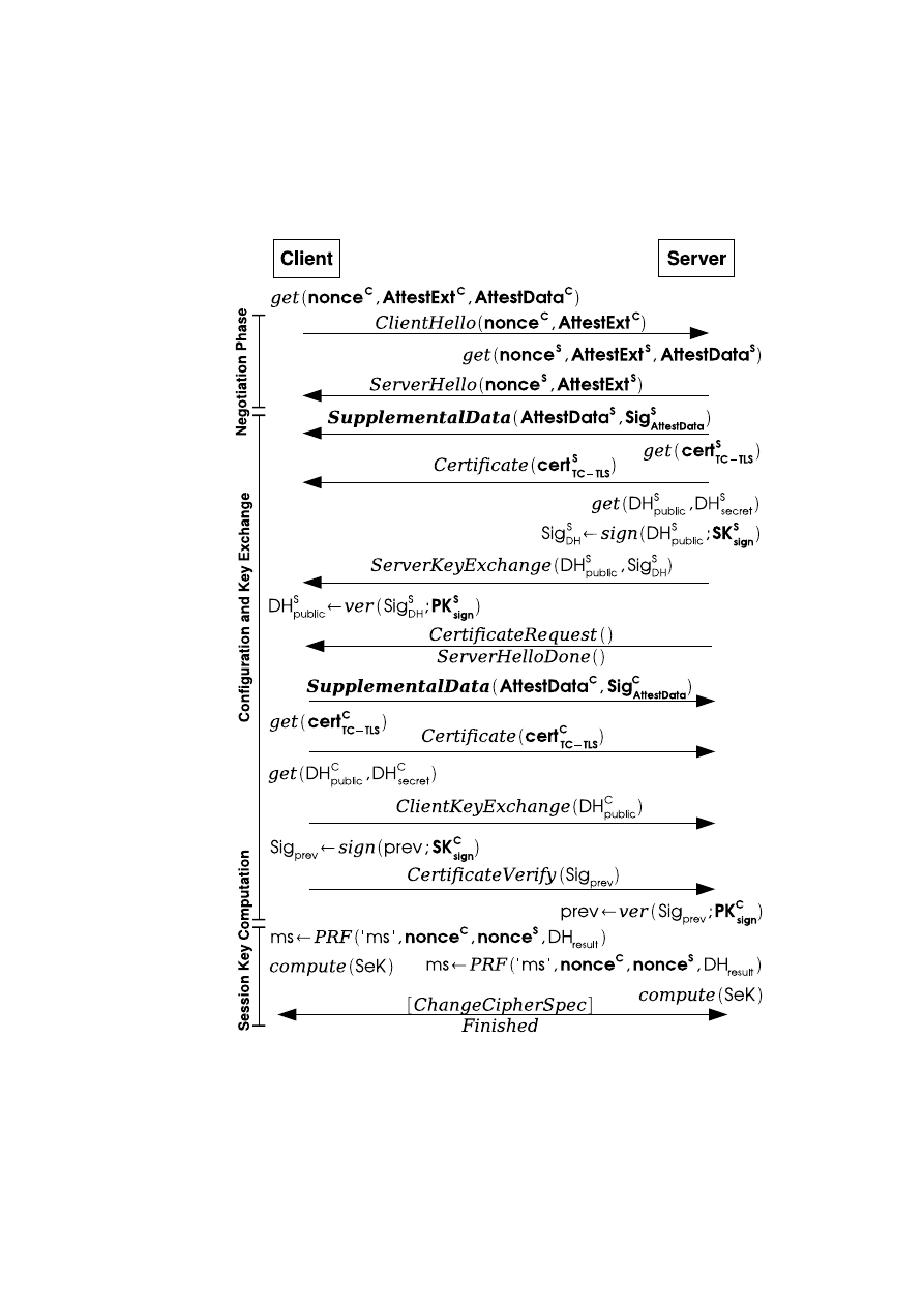
CHAPTER 9. TRUSTED CHANNELS USING OPENSSL
117
Figure 9.1: Adapted TLS DHE-RSA Handshake
OpenTC Document D05.6/V01 – Final R7628/2009/01/15/OpenTC Public (PU)

118
OpenTC D05.6 – Final Report of OpenTC Workpackage 5
In contrast to the common TLS design the nonces sent in the hello messages are taken
from a RNG seeded by the TPM at boot-time
4
. Furthermore, each side includes an
Attestation Extension (
AExt
), that is used to specify details concerning the configura-
tion/integrity information that will be exchanged.
Configuration and Key Exchange: Each peer provides evidence related to its con-
figuration and integrity. For this purpose we use additional
SupplementalData
mes-
sages as defined in Internet Engineering Task Force (IETF) RFC4680 (cf. Section 9.5,
[105]). Thus,
SupplementalData
messages are composed to transfer Attestation Data
(
aD
) representing configuration/integrity information.
aD
is signed using a secret key
(
SK
sign
) for authentication and integrity protection of configuration information. Fol-
lowing the
SupplementalData
message, each side provides a certificate (
cert
TCLS
)
including the respective public key (
PK
sign
) used to verify this signature.
Subsequently,
DHvalues
(
DH
public
,
DH
secret
) are computed on both sides.
DH
S
public
is signed using
SK
S
sign
to provide authentication evidence.
S
then sends
DH
S
public
and
a signature (
Sig
S
DH
) to
C
within the
ServerKeyExchange
message.
C
computes its
own values and sends
DH
C
public
to
S
using the
ClientKeyExchange
message. The
following
CertificateVerify
message is used to prove the possession of
SK
C
sign
, and
to authenticate
DH
C
public
, by signing a digest over all previously exchanged handshake
messages (
prev
) using
SK
C
sign
[27].
Session Key Computation: Following
CertificateVerify
, the TLS
master secret
(
ms
) is computed on both sides using
nonce
C
TPM
,
nonce
S
TPM
, a string indicating
that this is a
ms
, and the result of the final Diffie-Hellman computation as input to a
pseudo random f unction
(PRF). Subsequently, the Session Key (
SeK
) is derived
from the
ms
on both peers [27, p.24]. At last, the handshake is finalized by the
ChangeCipherSpec
protocol and final
Finished
messages. These
Finished
messages
are already encrypted using
SeK
, thus, a failure in key exchange would be noticed.
9.4.1
State Changes
Since state changes might happen on both peers while the Trusted Channel is in place,
we provide the possibility to exchange updated integrity information in a short re-
handshake. This re-handshake is triggered when a state change, e.g., the execution of
another software in the same compartment, occurs on any side, and if the correspond-
ing state monitoring option was selected in
AExt
(cf. Section 9.5.2)
5
. In case the
parties agreed on state change notification during the initial handshake, the following
procedure takes place: If a state change happens on one platform access to the
SeK
can be blocked and/or access to data belonging to the session is restricted depending
on the security policy of the application. Both sides are notified using
HelloRequest
,
ClientHello
and
ServerHello
, respectively. The updated integrity information for val-
idating the new configuration is securely transmitted to the counterpart encrypted using
SeK
and included in a data structure called State Change Extension (
SCExt
) (cf. Sec-
tion 9.5.2). Subsequently, a TLS resume message flow takes place [27]. After the short
4
We use the TPM as source for random values, because its RNG is considered as true random generator
in contrast to the pseudo-random generator implemented in OpenSSL. The advantage of this feature becomes
obvious with respect to the recently discovered security weakness in the OpenSSL RNG in Debian Linux
systems [112].
5
Changes inside the compartments can be detected using the Integrity Measurement Architecture (IMA,
[103]) proposed and implemented by IBM.
OpenTC Document D05.6/V01 – Final R7628/2009/01/15/OpenTC Public (PU)

CHAPTER 9. TRUSTED CHANNELS USING OPENSSL
119
TLS resume handshake the new session key
SeK
′
is computed and the communica-
tion can continue, or the channel is torn-down because the requirements of the security
policy of the peer are not fulfilled any longer.
9.5
Detailed Description of Attestation Data Structures
In this section we introduce credentials and extensions to TLS handshake messages we
use to set up a Trusted Channel, followed by an example of their usage.
9.5.1
Key Exchange Types and Certificate Elements
In a common TLS handshake certificates are used to authenticate the peers. There
are different certificate types used for different key exchange methods. Depending on
the type of certificate chosen or key exchange method supported, we add extensions
to the certificates. The certificate extensions and credentials we define are necessary
to bind the TLS channel to the endpoints whose configuration is reported, and to be
capable of proving that a certain TCB is in place. These new credentials are held in an
environment protected by TC mechanisms. Therefore, we act on the assumption that
these additional security measures justify stronger security assumptions concerning the
storage and usage of those credentials. In the following paragraphs we explain their
creation, storage and interdependency.
SKAE Key (
K
SKAE
) and SKAE: The
non
-
migratable
6
asymmetric key pair
K
SKAE
(
PK
SKAE
,
SK
SKAE
) is created after an AIK (
K
AIK
) has been certified and installed.
Its private part
SK
SKAE
is sealed to a specific TCB using the SRK (
K
storage
) and
never leaves the TPM unencrypted. We make use of the Subject Key Attestation Ev-
idence (
SKAE
) as proposed by the TCG [110]. In contrast to the intended purpose,
we use the
SKAE
as standalone element within our handshake, but we also foresee
the possibility to include it in a X.509 certificate. The
SKAE
basically consists of a
TPM_CERTIFY_INFO2
structure representing the TCB configuration that has to be
in place during key release (including a digest of
PK
SKAE
[118, p.96]) and a signature
over this structure (
Sig
SKAE
) by a
K
AIK
. Additionally, links to reference values can
be provided. The
SKAE
can vouch that
K
SKAE
was created by a Trusted Platform
that conforms to the TCG specification [114] and that a certain TCB configuration has
to be in place during release because of sealing.
Secure Encryption Key (
K
enc
) and Secure Signature Key (
K
sign
): We introduce
the asymmetric key pairs Secure Encryption Key
K
enc
(
PK
enc
,
SK
enc
) and Secure
Signature Key
K
sign
(
PK
sign
,
SK
sign
), that are considered long-lived and usable for
client compartments that wish to establish a Trusted Channel to a remote party. They
are created inside the TCB and sealed using
K
storage
.
Depending on the key exchange method supported and the respective certificate,
PK
enc
and/or
PK
sign
are included in the common TLS certificate (
cert
TCLS
) as encryption
or signature key (cf. Figure 9.2). Thus, either the public part of
K
enc
or
K
sign
are put
into the public key field of the X.509 certificate. In case of RSA and DH_RSA key
6
The private part of an asymmetric key pair labelled
non
−
migratable
never leaves the TPM unen-
crypted [114]
OpenTC Document D05.6/V01 – Final R7628/2009/01/15/OpenTC Public (PU)
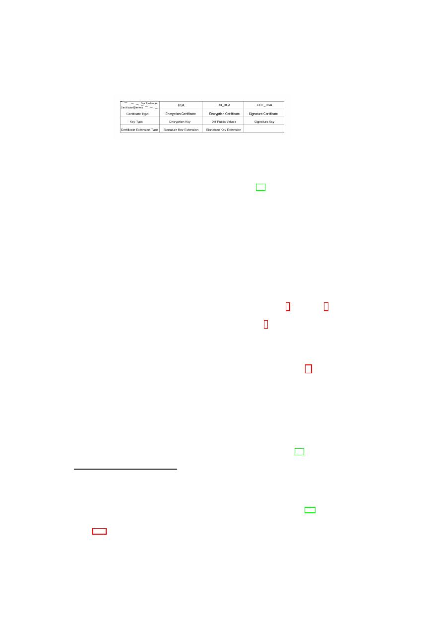
120
OpenTC D05.6 – Final Report of OpenTC Workpackage 5
Figure 9.2: Handshake Types and X.509 Certificates
exchanges,
K
sign
is included as Signature Key Extension to the TLS certificate. Its
X.509 format, including the use of extensions, is specified in [48]. The signature key is
needed in these handshakes to provide the binding between integrity information and
the endpoints. This is not feasible using the encryption key in those handshake types,
and using a single key for encryption and signing is considered insecure.
K
enc
and/or
K
sign
must be used for client and server authentication during the TLS
channel setup to guarantee the binding of the secure channel to the integrity state of
the endpoints. Therefore, the usual TLS authentication scheme will be used for server
authentication and its
cert
S
TCLS
will likely be signed by a CA like e.g. VeriSign. In
contrast, the TLS client authentication mechanism, optional for a standard TLS chan-
nel, must be used to guarantee the binding through
cert
C
TCLS
even if the actual and
reliable authentication of
C
might not be needed. Therefore, in this case
cert
C
TCLS
can
be self-signed.
SK
enc
and
SK
sign
are loaded and decrypted during the start of the platform and kept
inside the TCB. Subsequently, we need
K
SKAE
to authenticate
K
enc
7
and
K
sign
8
:
By signing
PK
enc
and
PK
sign
using
SK
SKAE
we provide twofold evidence: that the
TCB identified by the
SKAE
was in place during the signature
9
and it is a statement
from that TCB about
K
enc
and
K
sign
like: “I certify that
K
enc
,
K
sign
are correctly
treated, i.e., when decrypted, the keys are kept secret by myself”. If the verifier of the
SKAE
trusts the TCB attested by it, then the verifier can also trust the TCB’s statement
about the correct treatment of
K
enc
and
K
sign
. Therefore, the
TPM
_
Sign
()
function is
applied to sign
K
enc
’s and
K
sign
’s public parts with
SK
SKAE
at boot time
10
. The
resulting signature
Sig
BSEK
is held in the TCB memory space.
9.5.2
Extensions used in the TLS handshake
The extensions to the TLS protocol that will be introduced in the following paragraphs
are necessary to trigger and negotiate the exchange of configuration information as well
as for the transport of the additional configuration/integrity data. Extensions to the TLS
handshake protocol can be small data chunks added to the Hello messages [27] or com-
pletely new handshake messages. These extensions are explicitly foreseen by the TLS
7
In case DH_RSA key exchange was chosen, the DH parameters included in the certificate are signed.
8
It would also be possible to use
K
SKAE
instead of
K
sign
,
K
enc
for signing/encrypting during the
handshake. But then the involvement of the TPM every time a Trusted Channel is set up would be necessary.
This would result in a significant performance loss, especially in connection with server systems. Using
K
AIK
directly for this purpose is not allowed by the TCG specification.
9
The TCB must check digest at creation and digest at release of the stored key data objects [118, p.89]
before signing them with
SK
SKAE
to be sure that they were not compromised by a former TCB.
10
This has to be done at every system boot because otherwise the TCB update mechanism presented in
Section 9.6.2 could be compromised. Thus this signature is held in volatile memory.
OpenTC Document D05.6/V01 – Final R7628/2009/01/15/OpenTC Public (PU)
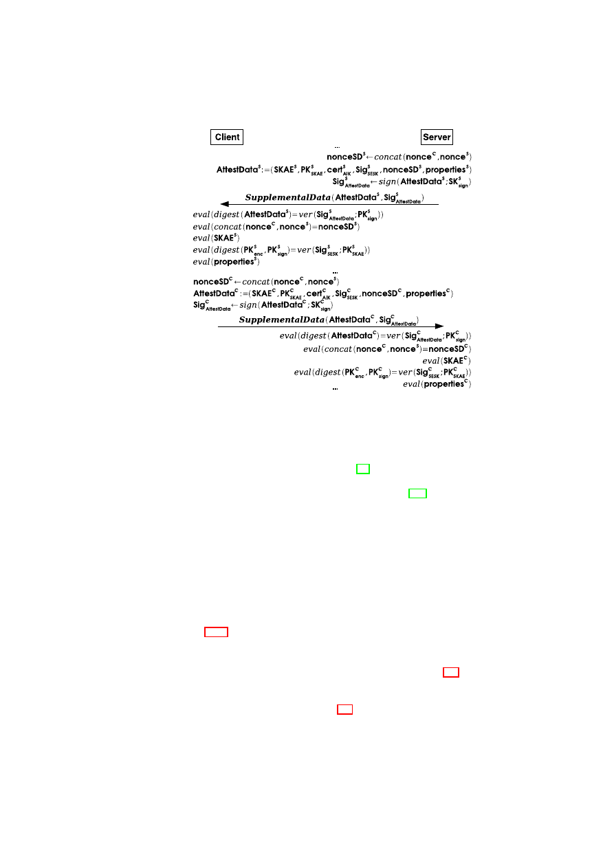
CHAPTER 9. TRUSTED CHANNELS USING OPENSSL
121
Figure 9.3: Supplemental Data Message Creation and Evaluation
specification to deal with advancements and changes in communication infrastructures.
There already exist several extensions to the TLS protocol, e.g., for sending client cer-
tificate URLs or explicit server name indication [95]. The basic concept for extending
TLS with an additional handshake message is described in RFC4680 available from the
Internet Engineering Task Force (IETF) Networking Group [105]. This RFC defines
the additional
SupplementalData
handshake message envisioned to carry additional
generic data, whose format must be specified by the application that uses it, and whose
delivery must be negotiated via Hello message extensions.
Hello message extensions:
Attestation Extension
or
State Change Extension
(
AExt
,
SCExt
) are transmitted within the
ClientHello
and
ServerHello
messages.
The first one is used in the initial handshake to negotiate which side (
C
and/or
S
) has
to attest to its state, the type of attestation and state-monitoring supported or if privacy
of configuration information is desired.
SCExt
, in turn, is used to inform the peer of
a state change on the counterpart and to transport configuration data in a re-handshake
(cf. Section 9.4.1).
Supplemental Data Message Creation and Evaluation: The
SupplementalData
message includes the
SKAE
,
PK
SKAE
,
cert
AIK
,
Sig
BSEK
, a concatenation of the
nonces sent in the TLS Hello messages and
properties
(see Section 9.3), depending
on what kind of attestation and key exchange was chosen. Furthermore, a Signature
Sig
aD
on
aD
is appended. This signature is needed to bind the
aD
structure to the re-
spective secure channel endpoint. In Figure 9.3 we show how
aD
is composed, while
the
properties
field is considered as black box, since its values vary depending on the
attestation concept chosen.
OpenTC Document D05.6/V01 – Final R7628/2009/01/15/OpenTC Public (PU)

122
OpenTC D05.6 – Final Report of OpenTC Workpackage 5
In our proof of concept prototype the
properties
data consists of measurements repre-
senting the images of the client compartments using the TLS Trusted Channel extracted
from a Configuration Data Structure (
CDS
) and corresponding signed
ref erence va
-
lues
(see Section 9.3). The
CDS
itself holds a list of measurements of the binary
images of all client compartments running on top of the TCB.
Determination of endpoint trustworthiness: The trustworthiness of the peer’s TCB
is determined by evaluating
Sig
SKAE
(cf. Section 9.5.1) and the TCB measurement in-
cluded in
SKAE
using
ref erence values
provided by trusted third parties. To verify
the validity of
K
sign
,
Sig
BSEK
is checked. Then the linkage between secure channel
endpoint and
aD
is verified by inspecting
Sig
aD
. Freshness of
aD
is guaranteed com-
paring
nonceSD
to the nonces sent the hello messages. Finally, the trustworthiness
of compartments running on top of the TCB is determined in a next step by evaluat-
ing
CDS
using either additional
ref erence values
provided by the peer within the
properties
data field or by trusted third parties.
Also other concepts of attestation are supported. If, e.g., the TCG attestation mech-
anism should be used, a digest of
nonceSD
,
PK
enc
and
PK
sign
is given as external
data to the
TPM
_
Quote
()
function of the TPM [114]. This is done to provide freshness
of TCG attestation data (
aD
TCG
) and to replace
Sig
BSEK
.
SKAE
is not needed here
because the AIK is used to sign the relevant values inside the TPM.
Since TLS handshake messages are usually sent in clear text, in case
privacy
of attestation information is desired by one of the communication partners, no
SupplementalData
messages are sent within the first handshake. Subsequently, a sec-
ond handshake is performed directly after the first one to exchange attestation informa-
tion encrypted using the session key negotiated in the previous handshake [105].
9.6
Generic System Architecture
Our generic system architecture is based on security frameworks as proposed, e.g.,
in [97], [102], and consists of an Application, Trusted Service, Virtualization as well
as TC-enabled Hardware Layer. We kept our approach generic, thus it is possible to
implement/integrate the components in different systems also on common operating
systems like, e.g., Linux or Windows. But, if these monolithic OSs are applied, some
constraints have to be considered when looking at the security of such implementations,
because in general they are not capable to ensure strong isolation of processes and
corresponding data.
TC-enabled Hardware Layer: The hardware layer has to offer TC extensions that
are conforming to the relevant TCG specifications (e.g., [114]). This essentially means
that it comprises a TPM chip and a compatible BIOS.
Virtualization Layer: The virtualization layer offers and mediates access to central
hardware components like, e.g., CPU and MMU. These tasks can be performed by
many kinds of virtualization techniques, namely hypervisors, microkernel approaches
or a common OS running a virtualization application, e.g., VMware [125].
Trusted Service Layer: This layer consists of security services [10] and provides
interfaces to the Application Layer. It also mediates and monitors access to virtualized
hardware resources. Subsequently, we briefly describe the main components of the
OpenTC Document D05.6/V01 – Final R7628/2009/01/15/OpenTC Public (PU)

CHAPTER 9. TRUSTED CHANNELS USING OPENSSL
123
TCB in our approach:
•
Trust Manager (
TM
) provides functionalities used for establishing Trusted Chan-
nels. To be able to provide this functionality
TM
bundles multiple calls to the
TPM into a simple API for calling instances. Thus, it offers functionality to gen-
erate keys, bind/unbind, seal/unseal, certify these keys or to report the current
measurement values of the TCB stored inside the TPM. The keys used in the ini-
tial handshake are computed and held by the
TM
. They never leave the TCB.
•
Compartment Manager (
CM
) is responsible for starting and stopping compart-
ments. It measures the compartment code when starting it and assigns a locally
unique ID to this compartment. This ID as well as the measurements are reported
to the Integrity Manager (see below).
•
Integrity Manager (
IM
) stores the compartment’s
properties
. In our approach
this means appending the measurements reported by
CM
together with a unique
ID to
CDS
(cf. Section 9.5).
IM
keeps the
CDS
secure by storing it inside the
TCB’s memory space and provides it to other TCB components.
•
Policy Manager (
PM
) stores platform and application policies and provides them
to other components of the TCB when needed
11
.
•
Storage Manager (
SM
) handles persistent data storing for the different compart-
ments.
Application Layer: In this layer the applications run in isolated compartments. This
can be either applications running directly on top of the underlying TCB or whole OSs.
9.6.1
Trusted Initialization
To be able to attest a platform’s configuration, its hard- and software components are
measured reliably and those measurements are stored securely. An ongoing measure-
ment process is effected originating from the Core Root of Trust for Measurement
12
that initiates the measurement process up to and excluding the Application Layer. Ev-
ery component that has to be loaded during the boot process is measured before passing
control over to it.
Consequently, a Chain of Trust (CoT) is established and the TCB is measured re-
liably. These measurements are stored inside the TPM and represent the static config-
uration in our approach, because it must be only modifiable with a subsequent reboot.
After the boot process platform monitoring is conducted by
CM
. Thus,
CM
extends
the CoT when a client compartment is loaded that runs on top of the TCB.
CDS
that
reflects the platform configuration is maintained by
IM
. The configuration of compart-
ments that run above the TCB represents the dynamic configuration because we allow
state changes to happen.
In our approach the CoT is initially built-up until the TCB is loaded and run-
ning.
To be able to provide support for Trusted Channels a RNG, seeded using
TPM
_
GetRandom
()
at boot-time, provides random. After the system has booted-up
and the TCB is in place,
TM
unseals
K
enc
and
K
sign
and signs their public parts with
SK
SKAE
.
TM
now holds
K
enc
,
K
sign
,
PK
SKAE
and
Sig
BSEK
. Thus, the system is
11
This component is not implemented yet, for the prototype we applied fixed policies.
12
This is a small piece of code initiating the measurement process at the very beginning of the boot process.
Usually, this code is located within the BIOS.
OpenTC Document D05.6/V01 – Final R7628/2009/01/15/OpenTC Public (PU)

124
OpenTC D05.6 – Final Report of OpenTC Workpackage 5
initialized and ready to set up a Trusted Channel.
9.6.2
TCB Update Management
We want to be able to change the TCB configuration without requesting a new TLS
certificate every time this is done. This is an important issue because on the one hand
re-certification of the TLS endpoint and its keys is expensive and on the other hand we
want the keys to be securely bound to a specific platform configuration to be able to
prove that they have not been compromised.
Using non-migratable keys during the handshake would be the safest way to protect
keys from being compromised but resealing such keys to a different TCB is not possible
[119]. Therefore, we present a procedure that allows the update of the TCB without
compromising the TLS keys and thus preserves the validity of the TLS certificate.
The problem here is that a system in an updated state (and its peer) has to be able to
judge its former state, because otherwise
K
enc
and
K
sign
may have been compromised
and a new certificate is needed. To achieve this, we keep a secure
changelog
. The
changelog
holds names and hash values of components that have been installed or
removed. Additionally it contains a link to a certificate by a trusted third party (e.g.,
manufacturer) that vouches for these values.
The update process starts with unsealing
SK
sign
and
SK
enc
. Then the new
package
13
is downloaded from a trustworthy entity together with
cert
update
containing the hash
value of the component after installation. Then,
TM
computes the foreseen config-
uration of the platform after the installation using the hash value comprised in the
certificate replacing the values of the removed component in the
CDS
and it updates
changelog
accordingly. Subsequently,
SK
sign
and
SK
enc
are sealed to this state. In a
last step the new
package
is installed. After this process the platform has to be rebooted
to let the changes take effect.
After the platform is initialized again, a new
K
SKAE
and related
SKAE
have to be
created. From then on the new
SK
SKAE
is used to sign
PK
enc
and
PK
sign
creating
Sig
BSEK
.
9.7
A Trusted Channel Implementation with OpenSSL
As basis for the implementation of the Trusted Channel we chose the Xen Hypervisor
[128]. The components –
TM
,
SM
,
IM
, and
CM
– mentioned in Section 9.6 have
been developed within the OpenTC [86, 68] and EMSCB [36] projects. We used these
services and extended them where needed.
9.7.1
Implementation Architecture
In order to confine the size of the Trusted Computing Base (TCB), we designed the
Trusted Channel split into two groups of components.
One group (the
TLS backend
), minimal and part of the TCB, performs the secu-
rity critical operations: encryption/ decryption, MAC calculation/verification and the
13
This could be package structures as used by several Linux distributions, e.g., rpm or deb.
OpenTC Document D05.6/V01 – Final R7628/2009/01/15/OpenTC Public (PU)
CHAPTER 9. TRUSTED CHANNELS USING OPENSSL
125
management of the TLS session are performed by
TM
, while the storage of sensitive
data like keys and certificates is done by
SM
14
.
The actual protocol implementation (the
TLS frontend
), instead, runs in the same
compartment as the application and is not needed to be trusted, thus its size is not
important. Applications already using the TLS implementation we chose to enhance
(OpenSSL) must be slightly modified to be able to set up a Trusted Channel instead of
the standard TLS secure channel.
But, our architecture is also capable to support the provision of Trusted Channels
as a service, running in a separate compartment and implemented as proxy. If so, the
application directly bound to the adapted TLS protocol is the service providing the
Trusted Channel to other applications.
We identified at least two types of interaction between a Trusted Channel service
and a generic application: explicit or implicit invocation. In the first case the applica-
tion explicitly requests the service (i.e. the proxy) for setting up a Trusted Channel. A
convenient implementation could use the SOCKS
15
protocol as a carrier of the neces-
sary calls. In case of implicit interaction, the application is unaware of the setup of the
Trusted Channel. A communication policy, set within the TCB, enforces transparently
the redirection of the application’s communications to the Trusted Channel service. A
convenient implementation could rely on a transparent proxy, like the one implemented
by SQUID [106].
With both explicit and implicit invocation, a scheme using a pair of proxies on
both sides can be set up, thus implementing a tunnel via Trusted Channel to carry the
end-to-end communication. With the explicit invocation, it is also possible so set up a
scheme with a proxy only on the client-side, directly connecting via Trusted Channel
to the server.
9.7.2
Enhancements to OpenSSL
OpenSSL [87] is a multi-platform and widespread software toolkit implementing cryp-
tographic operations, SSL [53] and TLS [27] protocols, the encoding/decoding of
X.509 [48] certificates and of other PKI-related formats like PKCS [60] standards.
It consists of two shared libraries (
libssl
and
libcrypto
) implementing all the
features and a command line tool (
openssl
) wrapping them. The libraries can also
be directly used by generic applications.
OpenSSL also offers the possibility to delegate the execution of (a subset of) cryp-
tographic operations to a separate module called engine. This is a shared library, with
a well-known interface, which can be dynamically loaded at run-time and used by
OpenSSL’s core libraries: more than one engine can be used at once. An engine can
be implemented in software or the library can be just the driver for a hardware crypto-
graphic device.
We built the Trusted Channel around three different enhancements to OpenSSL,
represented in the right-hand part of the Figure 9.4 and described in the following.
TLS protocol extensions: The stable version of OpenSSL (0.9.8x) does not imple-
ment any extension while the development version (0.9.9x) only includes hard-coded
14
The trusted initialization described in Section 9.6.1 is realized using the TrustedGRUB (tGRUB) boot
loader [4]
15
SOCKS is a well-known protocol for the communication with proxies [73]. The proxy is then the
application directly using the adapted TLS and running as service.
OpenTC Document D05.6/V01 – Final R7628/2009/01/15/OpenTC Public (PU)
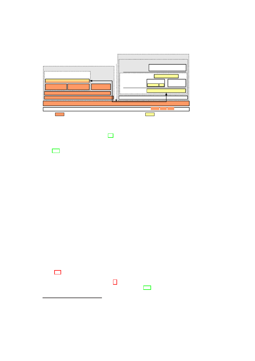
126
OpenTC D05.6 – Final Report of OpenTC Workpackage 5
DomU compartment (guest domain)
TLS frontend
Dom0 compartment (privileged domain)
TLS backend
(Trust and Storage managers)
OpenSSL enhancements
TCh engine (server-side stub)
Application memory address space
Communication channel (TCP/IP)
Xen Hypervisor
Hardware
CRTM CPU TPM
Components forming the TCB
Linux kernel
Linux kernel
TCG Software Stack (TSS)
Trusted Platform
Agent (TPA)
Software crypto
engine (libcrypto)
libssl
TCh engine (client-side stub)
libcrypto
Standard OpenSSL
Engine Interface
Application Interface
Application (or proxy) using
TCh-enhanced TLS
Hello ext SD
TCh management
Compartment
Manager
Figure 9.4: OpenSSL enhancements and Proof of Concept prototype
support for the extensions defined in [95] to
ClientHello
and
ServerHello
messages.
We implemented a mechanism to easily add generic and application-defined extensions
to these messages, usable to trigger the delivery of
SupplementalData
handshake mes-
sage [105], also newly implemented because not natively supported. These are the only
direct enhancements to OpenSSL, implemented as patch to
libssl
’s code, which ex-
pose an API for registering new Hello extensions or data for
SupplementalData
via
callback functions.
Trusted Channel management library: This is a completely new module realizing
the Hello extensions
AExt
and
SCExt
(on top of the enhanced
libssl
) and the
logic of the Trusted Channel’s specific operations. It also handles the parsing and
the validation of the credentials received during the handshake (
PK
AIK
,
PK
sign
and
PK
enc
) and it manages the validation of the attestation data (i.e.
aD
and
Sig
aD
) carried
through the
SupplementalData
message. Finally it provides the application with an
interface to set up the Trusted Channel.
TLS backend via split engine: To implement our concept of delegating the secu-
rity critical operations, we implemented an OpenSSL engine split into two parts. The
shared library implementing the engine interface runs in the application (or proxy)
memory space together with the Trusted Channel management library and
libssl
:
they all form the
TLS frontend
. The latter requests the execution of critical opera-
tions over a communication channel at the
TLS backend
, which actually provides the
functions needed by the TLS protocol and runs in a different compartment as part of
the TCB.
9.7.3
Proof of Concept (PoC) Prototype
Figure 9.4 shows a PoC prototype of our OpenSSL-based Trusted Channel implemen-
tation built upon Xen.
The
TLS backend
runs in Domain0
16
– the Xen privileged domain – and uses
TrouSerS – an open source TCG Software Stack (TSS) [117] – to access the TPM
capabilities. It can be decomposed in: (1) server-side stub, the endpoint for the com-
16
Because the root account in Domain0 has full access to all resources and services, protection against a
malicious administrator is not possible in our PoC.
OpenTC Document D05.6/V01 – Final R7628/2009/01/15/OpenTC Public (PU)

CHAPTER 9. TRUSTED CHANNELS USING OPENSSL
127
munication with the
TLS frontend
via TCP-based protocol, (2) the Trusted Platform
Agent (TPA)
17
in charge of dealing with the life-cycle management of all credentials
and implementing a minimal Storage Manager and (3) a software module partially im-
plementing a Trust Manager
18
which performs all cryptographic operations during the
handshake and the TLS session.
9.8
Security Considerations
In this section we carry out a short reevaluation of the security requirements adopted
from [10] and presented in Section 9.2.1 with regard to our new approach.
(SR1) Secure channel properties: TLS provides secure channel properties during
transmission. On the endpoints the TCB offers those properties. Confidential-
ity and integrity are provided by trusted initialization, isolation of the TCB and
platform monitoring. The concept is even able to provide protection against a ma-
licious administrator, because the measurements of the TCB cannot be faked, and
if the TCB is properly configured (expressed by its measurements), it should not
be possible to tamper with the TCB while running. The TCB also takes care of
authenticity and freshness by securely storing nonces and session keys. As a result
of platform monitoring, every manipulation of a compartment is noticed and ac-
cess to sensitive data can be barred if necessary to ensure the security properties.
Furthermore, SM provides storage that can preserve secure channel properties in
case that data is stored persistently.
(SR2) Authentic linkage of configuration information and secure channel: Au-
thenticity of communication is guaranteed by providing
cert
TCLS
that is used to
authenticate the endpoints (cf. Section 9.4). The secure linkage of configuration
information to the endpoints is verified by evaluating the
SKAE
,
Sig
BSEK
and
Sig
aD
.
We assume a secure as well as specification conformant creation of
K
storage
(Stor-
age Root Key) and
AIK
. We further assume that a TCB whose configuration has
been evaluated by the counterpart is able to reliably transfer configuration infor-
mation related to the client compartments and takes care of the secure storage and
application of the keys used within the handshake. A possibility for the retrieval
of CA keys for verification of signatures is also anticipated.
After a successful evaluation of the credentials transferred, these statements can
be made: All keys are bound to the same TCB. This TCB is specified by mea-
surement values incorporated in
SKAE
. Thus, the
properties
and the
changelog
sent originate from this TCB because
SK
sign
and
SK
enc
are sealed to this TCB
and signed by
SK
SKAE
.
SeK
,
K
sign
and
K
enc
are kept inside the TCB during the whole session. Due to
the isolation property of the TCB those keys cannot be disclosed to compartments
or to other platforms. This is the reason why we claim to provide better forward
secrecy for session keys in case of using RSA as key exchange method. Relay
attacks as well as attacks to obtain any keys establishing the Trusted Channel are
17
TPA has been developed within the OpenTC [86] project
18
we chose to use the OpenSSL library
libcrypto
OpenTC Document D05.6/V01 – Final R7628/2009/01/15/OpenTC Public (PU)

128
OpenTC D05.6 – Final Report of OpenTC Workpackage 5
not feasible assumed that no hardware attacks are applied.
(SR3) Privacy: With regard to configuration data transmitted, we provide a possi-
bility to send it encrypted to protect potentially sensitive data (see Section 9.5.2).
Only the configuration of TCB and the TLS client compartments is reported to
the peer, keeping the information disclosed to the other platform as minimal as
possible. Furthermore, every communication partner can assess the trustworthi-
ness of its counterpart and thus, make a judgment on whether it will treat personal
information according to its security policy.
9.9
Functional Considerations
To meet the functional requirements (cf. Section 9.2.2) following measures have been
taken:
(FR1) Fast deployment support: To make a fast and widespread deployment of our
approach possible, we decided to adapt TLS as a commonly used protocol to sup-
port the exchange of endpoint configuration information. Furthermore, we took
an existing TLS implementation (OpenSSL) and adapted it to our needs. Thus,
the effort that had to be put into the implementation of our approach was moder-
ate and will presumably be even smaller for other existing TLS implementations,
since we had to add features like, e.g, extension support, that normally should
already be integrated. Additionally, we only applied mechanisms and concepts
already defined in existing specifications. Thus, it is not necessary to go through a
time-consuming specification process. Finally, our new concept is able to support
all common key exchange methods of TLS.
(FR2) Minimal
costs:
For
the
implementation
of
our
concept
we
used
commercial
off-the-shelf
hardware.
Thus, no expensive cryptographic hardware is necessary. Only Open Source
Software was used for the realization of the software part. The resulting code is
available without charge and incurs no additional license costs for the user. In
contrast to [10], we also decoupled TLS certificate keys from a fixed platform
configuration by introducing a TCB update mechanism (cf. Section 9.6.2) that
enables updates of the TCB without losing track of the states the platform went
through.
(FR3) Minimal overhead during handshake: To be able to ensure fast response
times, we do not rely on the direct usage of the TPM. This would induce too much
overhead since the TPM is currently connected to a LPC-Bus that has only limited
bandwidth and its processing power is also very restricted. Thus, we decided to
involve the TPM only for system initialization. From then on all functionalities are
provided by Trusted Services. Thus, even in a server environment fast response
times are ensured. The overhead induced by transferring attestation information
is minimal, since the amount of data transferred is comparatively small. We tested
this in a testbed and the results showed that there is no significant performance
overhead induced by inserting and transferring the extensions.
(FR4) Flexible configuration reporting: By incorporating the possibility to transfer
whatever integrity/ configuration information (e.g., see [96]) one may want to pro-
OpenTC Document D05.6/V01 – Final R7628/2009/01/15/OpenTC Public (PU)

CHAPTER 9. TRUSTED CHANNELS USING OPENSSL
129
vide, using a black box
properties
field, we ensure interoperability and safeguard
forward compatibility of our concept. We showed that, e.g., the TCG approach
to use the
TPM
_
Quote
()
[119, p.160] for attestation is also supported (cf. Section
9.4).
(FR5) Backward compatibility: To be sure that also peers only supporting common
TLS secure channels can communicate with systems that use our concept, we only
used or defined extensions to the different specifications. Those extensions are
ignored if they are not supported. Furthermore, we kept the whole implementation
separated from the application layer offering a transparent usage of the Trusted
Channel. Thus, applications do not have to be adapted to make use of our concept.
9.10
Summary
In this paper we presented a security architecture as well as an adaptation of the TLS
handshake to provide a Trusted Channel that combines the security features of a se-
cure channel with the ability to determine the trustworthiness of the communication
endpoints.
After a detailed description of our design and its implementation, we showed that
our approach is able to meet the strict requirements set in the beginning. By meeting
these requirements we are able to provide a means to fight off many threats to today’s
and tomorrow’s distributed applications with a concept that is deployable in the short-
term.
In a next step we plan to hand in a RFC for our extensions to the IETF consensus
process and we work on adapting IPSec to be used as Trusted Channel protocol. A for-
mal security analysis of the presented TLS handshake is subject to future work as well
as the adaptation of other protocols, e.g., SSH, to fit the needs of a Trusted Channel.
OpenTC Document D05.6/V01 – Final R7628/2009/01/15/OpenTC Public (PU)

Chapter 10
Towards Dependability and
Attack Resistance
Bernhard Jansen, HariGovind V. Ramasamy, Matthias Schunter, and Axel Tanner
(IBM)
10.1
Introduction to Dependable Virtualization
In this chapter, we explore opportunities for dependability and security made available
by virtualization, and provide detailed information on how virtualization affects sys-
tem reliability. We make four contributions: (1) a survey of dependability and security
enhancements enabled by virtualization, (2) a prototype demonstrating the effective-
ness of hypervisor-based intrusion detection, (3) reliability models and analysis of the
effects of virtualization, and (4) an architecture for a reliability-enhanced Xen VMM
that leverages a subset of the enhancements.
We describe ways of leveraging virtualization for dependability and security en-
hancements, such as response to load-induced failures, administration of patches in an
availability-preserving manner, enforcement of fail-safe behavior, proactive software
rejuvenation, and intrusion detection and protection. We describe in detail a Xen-based
implementation of a subset of these enhancements, particularly, intrusion detection and
protection. The intrusion detector, called X-Spy, uses a privileged Xen VM to monitor
and analyze the complete state of other VMs co-located on the same physical platform.
X-Spy is close enough to the target monitored to have a high degree of visibility into the
innards of the target (like host-based intrusion detection schemes). At the same time,
thanks to the isolation provided by the VMM, X-Spy is far enough from the target to
be unaffected even if the target becomes compromised (like network-based intrusion
detection schemes). A key challenge in implementing X-Spy was the semantic gap,
i.e., the proper interpretation of process information gathered from the VMs monitored
in a completely different VM.
We provide detailed information on how virtualization affects an important depend-
ability attribute, namely reliability. The VMM is increasingly seen as a convenient
layer for implementing many services such as networking and security [41] that were
traditionally provided by the operating system. We show why such designs should be
viewed with more caution. We use combinatorial modeling to analyze multiple design
choices when a single physical server is used to host multiple virtual servers and to
130
CHAPTER 10. TOWARDS DEPENDABILITY AND ATTACK RESISTANCE 131
quantify the reliability impact of virtualization. In light of the prevailing trend to shift
services out of the guest OS into the virtualization layer, we show that this shift, if not
done carefully, could adversely affect system reliability.
We describe a reliability-enhanced Xen VMM architecture, called R-Xen, that com-
bines replication, intrusion detection, and rejuvenation. Normally, the Xen VMM con-
sists of a relatively small hypervisor core and a full-fledged privileged VM called Dom0
that runs a guest OS (Linux). Regular VMs running on the Xen VMM are called user
domains or DomUs. Because of its size and complexity, Dom0 is the weak point in
the reliability of the Xen VMM. R-Xen focuses on improving Dom0 reliability (and
thereby improving the Xen VMM reliability) through three-fold replication. The three
Dom0 replicas each contain X-Spy implementations to mutually monitor each other
and thus detect the presence of faults and/or intrusions in the other two. If two replicas
report to the hypervisor that the third is corrupted, the hypervisor terminates and reju-
venates the corrupt replica. If the replica terminated happens to be the primary replica
that provides device virtualization for user domains, then one of the two backups be-
comes the new primary.
The remainder of the chapter is organized as follows. Section 1.4 describes re-
lated work in the area of virtualization-based dependability and virtualization-based
intrusion detection. In Section 10.2, we describe at a high-level several dependabil-
ity and security enhancements (including intrusion detection and protection) that are
made possible by virtualization. Section 10.3 describes X-Spy, our Xen-based proto-
type implementation of intrusion detection and protection. Section 10.4 analysis the
reliability impact of virtualization and highlights the importance of VMM reliability
to the overall reliability of a virtualized physical node. Motivated by the conclusions
of our reliability analysis and leveraging our X-Spy implementation, Section 10.5 de-
scribes an architecture for a more reliable Xen VMM.
10.2
Using Virtualization for Dependability and Secu-
rity
Commodity operating systems provide a level of dependability and security that is
much lower than what is desired. This situation has not changed much in the past
decade. Hence, the focus has shifted to designing dependable and secure systems
around the OS problems. Thanks to the flexible manner in which VM state can be
manipulated, virtualization can enable such designs. In particular, VM state, much like
files, can be read, copied, modified, saved, migrated, and restored [41]. In this section,
we give several examples of dependability and security enhancements made possible
by virtualization.
Coping with Load-Induced Failures: Deploying services on VMs instead of
physical machines enables a higher and more flexible resilience to load-induced fail-
ures without requiring additional hardware. Under load conditions, the VMs can be
seamlessly migrated (using live migration [23]) to a lightly loaded or a more pow-
erful physical machine. VM creation is simple and cheap, much like copying a file.
In response to high-load conditions, it is much easier to dynamically provision addi-
tional VMs on under-utilized physical machines than to provision additional physical
machines. This flexibility usually compensates for the additional resources (mainly
memory) needed by the hypervisor.
OpenTC Document D05.6/V01 – Final R7628/2009/01/15/OpenTC Public (PU)

132
OpenTC D05.6 – Final Report of OpenTC Workpackage 5
Patch Application for High-Availability Services: Typically, patch application
involves a system restart, and thus negatively affects service availability. Consider a
service running inside a VM. Virtualization provides a way of removing faults and vul-
nerabilities at run-time without affecting system availability. For this purpose, a copy
of the VM is instantiated, and the patch (be it OS-level or service-level) is applied on
the copy rather than on the original VM. Then, the copy is restarted for the patch to
take effect, after which the original VM is gracefully shut down and future service re-
quests are directed to the copy VM. To ensure that there are no undesirable side effects
due to the patch application, the copy VM may be placed under special watch for a
sufficiently long time while its post-patch behavior is being observed before the origi-
nal VM is shut down. If the service running inside the VM is stateful, then additional
techniques based on a combination of VM checkpointing (e.g., [7]) and VM live mi-
gration [23] may be used to retain network connections of the original VM and to bring
the copy up-to-date with the last correct checkpoint.
Enforcing Fail-Safe Behavior and Virtual Patches: The average time between
the point in time when a vulnerability is made public and a patch is available is still
measured in months. In 2005, Microsoft took an average time of 134.5 days for issuing
critical patches for Windows security problems reported to the company [126]. Devel-
oping patches for a software component is a time-consuming process because of the
need to ensure that the patch does not introduce new flaws or affect the dependencies
between the component involved and other components in the system. In many cases,
a service administrator simply does not have the luxury of suspending a service imme-
diately after a critical flaw (in the OS running the service or the service itself) becomes
publicized until the patch becomes available.
Virtualization can be used to prolong the availability of the service as much as
possible while at the same time ensuring that the service is fail-safe. We leverage the
observation that publicizing a flaw is usually accompanied by details of possible attacks
exploiting the flaw and/or symptoms of an exploited flaw. Developing an external
monitor to identify attack signatures or symptoms of an exploited flaw may be done
independently of patch development. The monitor may also be developed much faster
than the patch itself, because the monitor may not be subject to the same stringent
testing and validation requirements.
Consider a service running inside a VM rather than directly on a physical machine.
Then, a VM-external monitor, running in parallel to the VM, can be used to watch for
these attack signatures or detect the symptoms of exploitation of the flaw. If attack
signatures are known, the VM-external monitor can be used to block the attack, e.g. by
filtering the incoming network stream, to terminate interaction with the attack source,
or to protect targeted structures inside the VM, e.g. the system call table. If only symp-
toms of exploitation are known, detection of a compromise can be used to immediately
halt the VM. The monitor could be implemented at the VMM level or in a privileged
VM (such as Dom0 in Xen [11]). If it is important to revert the service to its last correct
state when a patch becomes available, then the above technique can be augmented with
a checkpointing mechanism that periodically checkpoints the state of the service with
respect to the VM (e.g., [7]).
Proactive Software Rejuvenation: Rebooting a machine is an easy way of rejuve-
nating software. The downside of machine reboot is that the service is unavailable dur-
ing the reboot process. The VMM is a convenient layer for introducing hooks to proac-
tively rejuvenate the guest OS and services running inside a VM in a performance- and
availability-preserving way [93]. Periodically, the VMM can be made to instantiate a
reincarnation VM from a clean VM image. The booting of the reincarnation VM is
OpenTC Document D05.6/V01 – Final R7628/2009/01/15/OpenTC Public (PU)

CHAPTER 10. TOWARDS DEPENDABILITY AND ATTACK RESISTANCE 133
done while the original VM continues regular operation, thereby maintaining service
availability. One can view this technique as a generalization of the proactive recovery
technique for fault-tolerant replication proposed by Reiser and Kapitza [93].
As mentioned above in the context of patch application, techniques based on VM
checkpointing and live migration may be used to seamlessly transfer network connec-
tions and the service state of the original VM to the reincarnation VM. It is possible to
adjust the performance impact of the rejuvenation procedure on the original VM’s per-
formance. To lower the impact, the VMM can restrict the amount of resources devoted
to the booting of a reincarnation VM and compensate for the restriction in resources by
allowing more time for the reboot to complete.
One can view the above type of rejuvenation as a memory-scrubbing technique
for reclaiming leaked memory and recovering from memory errors of the original VM.
More importantly, such a periodic rejuvenation offers a way to proactively recover from
errors without requiring failure detection mechanisms (which are often unreliable) to
trigger the recovery.
Intrusion Detection and Response: Based on the location of the intrusion detec-
tion sensors, intrusion detection system (IDS) implementations are broadly classified
into host-based IDS (HIDS) and network-based IDS (NIDS) [46]. A NIDS monitors
network traffic from and to the target, and analyzes the individual packets for signs
of intrusion. Because of its isolation from the target monitored, a NIDS decreases
its susceptibility to attacks and is largely unaffected by a compromised target. How-
ever, as network traffic becomes increasingly encrypted and as the NIDS has no direct
knowledge of the effects or properties of the attack targets, the usefulness of NIDS is
decreased. The fact that not all intrusions may manifest their effects in the form of
malicious traffic also lowers the utility of NIDS. The sensors of a HIDS are placed
on the target machine itself, giving them a high degree of visibility into the internals
of the target, enabling closer monitoring and analysis of the target than NIDS does.
However, the location of HIDS on the same “trust compartment” as the target is also a
disadvantage: after an intrusion into the target, the HIDS may no longer be trusted.
Virtualization provides a way of removing the disadvantages of HIDS and NIDS,
while retaining their advantages. In our approach, the sensors are placed in a special
privileged VM (called the secure service VM or SSVM) used for monitoring other VMs
hosting regular production services (called production VMs or PVMs). The placement
of the sensors on the same physical machine but in a different VM allows monitoring
and analysis of the complete state of other VMs via the VMM, and at the same time,
keeps the sensor out of reach of a potentially compromised VM and in a secure vantage
position.
The twin characteristics of proximity to the target and isolation from the target
also make the SSVM a convenient location for implementing intrusion response mech-
anisms. The secure vantage point of the SSVM allows one to implement otherwise
difficult responses, e.g., even a simple response like ‘shutdown a compromised sys-
tem’ may not be effectively triggered from inside the compromised system. On the
other hand, it is easy and effective to suspend the operations of a compromised PVM
from the SSVM. In addition, the SSVM can instruct the VMM to provision a healthy
replacement PVM or block suspicious system calls that may potentially tamper with
the integrity of the kernel.
For effective rejuvenation of a compromised PVM by re-provisioning a new PVM,
it is not sufficient to merely boot the new PVM from a clean state. The new PVM
might still possess all the vulnerabilities of the compromised one. Hence, it is impor-
tant to perform a forensic analysis of the compromised PVM’s state to remove as many
OpenTC Document D05.6/V01 – Final R7628/2009/01/15/OpenTC Public (PU)

134
OpenTC D05.6 – Final Report of OpenTC Workpackage 5
vulnerabilities as possible. Such an analysis is facilitated by the virtualized environ-
ment hosting the SSVM. The SSVM can obtain not only modified files of a suspended
PVM, but also its complete run-time state from the memory dump created at the time
of suspension. The memory dump can be examined using the same techniques as the
one used to observe the state of a running PVM from the SSVM for the purpose of
intrusion detection.
10.3
Xen-based Implementation of Intrusion Detection
and Protection
In this section, we describe the prototype implementation of a subset of the security
enhancements mentioned above, namely, intrusion detection and protection for VMs.
Later, in Section 10.5, we leverage the implementation for enforcing fail-safe behavior
and for triggering software rejuvenation in our construction of R-Xen.
10.3.1
Intrusion Detection and Protection for Xen Virtual Ma-
chines
We have implemented an intrusion detection and protection framework called X-Spy.
The core idea is to use a secure service VM (SSVM) that monitors one or more pro-
duction VMs (PVM). The SSVM performs the following functions:
Lie Detection The SSVM accesses the memory of the PVM and compares actual crit-
ical system data (processes, mounts, etc.) against data obtained by executing
normal Unix commands inside the PVM. If the comparison yields discrepancies,
then that is indicative of a compromised PVM. In contrast to earlier hypervisor-
based intrusion detection work, X-Spy’s detection mechanisms are more com-
prehensive and include lie detection at the level of processes, network connec-
tions, modules, and file system mounts.
Protection We have added a system call inspector to Xen that allows the monitoring
of the system calls within the PVM for the purpose of protecting relevant foren-
sic information (like log files) and the integrity of the kernel (kernel structures,
modules, and memory).
X-Spy uses the Xen [11] VMM developed by Cambridge University and guest VMs
running the Linux 2.6 operating system. Nevertheless, the concepts such as system call
analysis and lie detection can be applied to other operating systems such as Microsoft
Windows. All X-Spy components are implemented either in the Xen hypervisor or in
the SSVM. While their implementation logic depends on the guest OS, X-Spy does not
require any modification to the guest OS of the PVM.
Limitations
To overcome the semantic gap, we assume some knowledge of the kernel structures of
the guest operating system (specifically, Linux kernel 2.6) so that X-Spy components
OpenTC Document D05.6/V01 – Final R7628/2009/01/15/OpenTC Public (PU)

CHAPTER 10. TOWARDS DEPENDABILITY AND ATTACK RESISTANCE 135
can be appropriately coded. If the guest operating system is upgraded to a newer ver-
sion in which kernel structures are different, then the X-Spy components need to be
re-coded appropriately. That fact may be an impediment to commercializing X-Spy,
as it implies an ongoing commitment to develop and patch X-Spy components to keep
pace with upgrades to the guest operating system.
For detecting hidden processes, X-Spy requires that the scheduler of the PVM’s
guest OS keep a list of processes that need to be scheduled in a standard place within
a known memory structure. If an attacker is able to replace the scheduler with her own
one having a different list of processes, the detection approach would be subverted.
That is why it is important to protect the integrity of the kernel code (for example,
using mechanisms that we describe in Section 10.3.4).
The SSVM needs read access to the memory of the PVMs for the purpose of mon-
itoring them. In addition, it must be possible to do an SSH login to the PVM from the
SSVM and execute normal Unix commands. These requirements are contrary to the
isolation guarantees of the hypervisor. The SSVM itself could become a high-value at-
tack target, and accordingly, needs stronger protection. Several measures can be taken
to strongly reduce the potential of the SSVM getting compromised. For example, as the
SSVM is a special-purpose VM (in contrast to PVMs), it can be hardened, its function-
ality reduced solely to that of monitoring the PVMs, and its access restricted through a
specific administrative interface.
10.3.2
Architecture of X-Spy
The architecture of the X-Spy intrusion detection framework is shown in Figure 10.1.
Our architecture consists of a PVM and a SSVM running on top of the same hardware
and Xen hypervisor. In our implementation, both the SSVM and the PVM run Linux
kernel 2.6. The SSVM obtains the run-time state of the PVM through the Xen hyper-
visor, which is at a lower level of abstraction than both the SSVM and the PVM. The
SSVM has access to the raw devices of the PVMs (memory, disk, network); however,
the difficulty lies in the SSVM properly interpreting the data because of a semantic
gap [21]. For example, the physical memory of the host system will be made available
in chunks as pseudo-physical memory to the VMs. In addition, the (possibly different)
operating systems of the VMs use a virtual address space on top of the physical mem-
ory, leading to the problem of properly interpreting raw memory locations in a different
context.
10.3.3
Intrusion Detection by means of a Lie-Detector
The basic idea of the Lie-Detector is to compare the insider and outsider views of the
system to identify objects (processes, files etc.) that try to hide themselves from the
operating system [12]. Such behavior is typical of rootkits, which are then used to
hide other (typically malicious) software, but is also sometimes characteristic of DRM
functionality (e.g. the XCP content protection technology by Sony BMG in 2005). The
Lie-Detector (Figure 10.1) consists of three major functionalities:
1. PVM Information Collection: The Lie-Detector collects information about the
PVM by two different means: the native interface and the frontDoor interface.
OpenTC Document D05.6/V01 – Final R7628/2009/01/15/OpenTC Public (PU)
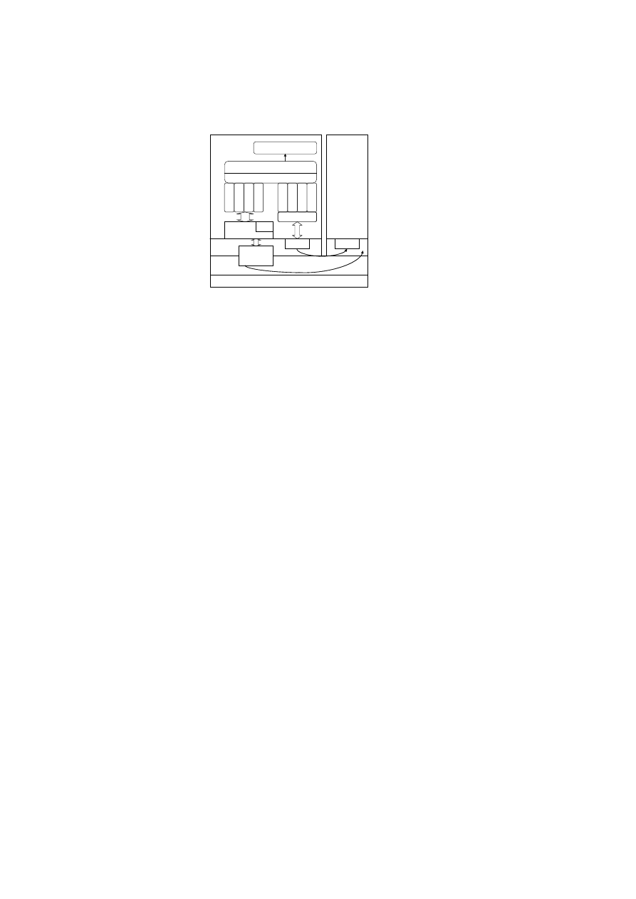
136
OpenTC D05.6 – Final Report of OpenTC Workpackage 5
SSVM
PVM
N
C
R
L
P
L
L
M
L
L
M
o
L
L
PMT
GDMAL
n
e
ts
ta
t
p
s
ls
m
o
d
m
o
u
n
t
ssh
ssh
Lie - Detector
MTI
TCP/IP
TCP/IP
TCP/IP
TCP/IP
Normalizer
Kernel
Xen
User Space
Hardware
Event Handling
Figure 10.1: Architecture of the X-Spy Lie-Detector components.
2. PVM Information Normalization: The PVM information collected via the native
interface is normalized to a format equivalent to that of commands executed
through the frontDoor interface.
3. Analyze-and-Compare: The normalized information from the native and front-
Door interfaces is then compared to identify differences that are indicative of
maliciously hidden system resources and to minimize false positives. Any find-
ings will be reported through the Event Handling component.
We describe the above functionalities in detail below.
Memory Translation Interface (MTI)
One of the main components of X-Spy is
a Memory Translation Interface (MTI) that allows the SSVM full access to a PVM’s
pseudo-physical and virtual memory in a convenient fashion. The MTI has two parts:
1. An extension to the Xen hypervisor, which performs address translation and
traversal of the page tables.
2. A Linux kernel device driver that runs in the SSVM kernel and provides two in-
terfaces, namely,
/dev/mem_domX
and
/dev/kmem_domX
. These interfaces
are functionally equivalent to the
/dev/mem
and the
/dev/kmem
device files,
respectively, and allow the root user in the SSVM kernel access to the PVM’s
physical memory and kernel memory contents, respectively.
One challenge to overcome when implementing the MTI was that the SSVM cannot
access a PVM’s foreign memory as it corresponds to a different context. Therefore,
the MTI has to emulate the memory management unit by translating the address to
the right format and re-mapping it from the PVM memory space onto the memory
space of the Lie-Detector process running in the SSVM. For this purpose, we have
developed two user-space libraries that the MTI uses: the Guest Domain Memory Ac-
cess Library or GDMAL and the Process Memory Translator or PMT. The GDMAL
provides read-write access to the PVM’s memory. Within the PVM’s memory, the
PMT allows access to the virtual address space of PVM processes. In addition, the
PMT provides some helper functions to facilitate the use of the
/dev/mem_domX
OpenTC Document D05.6/V01 – Final R7628/2009/01/15/OpenTC Public (PU)

CHAPTER 10. TOWARDS DEPENDABILITY AND ATTACK RESISTANCE 137
and
/dev/kmem_domX
interfaces. The PMT performs the process address transla-
tion by extracting the memory management information for the process from the OS-
specific task (process) description data structure. When the guest OS is Linux, as in
our case, the PMT extracts the
mm_struct
data structure from the
task_struct
data structure.
The native interface is used to collect PVM information “from the outside” through
the raw access made available by the Xen hypervisor, e.g. by accessing the PVM’s
memory via the MTI, and to collect host-specific data via special user-space libraries
that we have developed, namely the process list library (PLL), the network connection
and routing library (NCRL), and the module list library (MLL).
The second interface, called the frontDoor interface, is used to obtain PVM infor-
mation by doing an SSH login to the PVM and executing normal Unix commands.
The Lie-Detector normalizes the information collected from both interfaces, and then
compares them. If the comparison yields discrepancies in the information collected
from those two sources, this is strongly indicative of an intrusion. Obviously, it is not
possible to obtain information through the frontDoor interface and the native interface
at exactly the same time. This timing difference may lead to false positives, and we
explain below how to overcome this problem. We implement comparison methods for
processes, network connections, kernel modules, file system mounts and files.
The MTI provides access to the PVM’s raw kernel virtual memory but lacks any
semantic context. To fix this shortcoming, we manually created a memory offset file
for each library
1
. Based on these files, the libraries such as PLL, NCRL, and MLL,
implement the logic to extract all data values of interest from the raw kernel virtual
memory. Each offset file stores the offset values of the start of each data item of interest
from the beginning of the containing structure.
Process List
The PLL acts on information provided by the MTI to generate output
similar to that of the
ps
command. This is done by accessing and then traversing the
doubly-linked circular task list via the MTI.
Our comparison is based on the multitude of information extractable from this
task_struct
data structure, such as PID, state, parent, open files, registers, pri-
orities, locks, and memory management information. However, not all fields in the
data structure are used. For example, the running time of a process as seen by the
native interface query and the frontDoor interface query are bound to slightly differ,
owing to the difference in the time of query.
This comparison will detect processes in the PVM that actively try to hide their
presence or change their appearance (e.g. the owner) from queries made from within
the PVM. This will identify rootkit-like behavior, as non-hiding processes can be iden-
tified by more conventional (non-hypervisor-based) malware detection tools.
Note that simply comparing the process information from the native and frontDoor
interfaces results in false positives because of frequent changes to the process table.
We fix this by executing a native access (outsider view) before and after the frontDoor
query (insider view). If a given process disappeared in the second query but is again
visible in the third, we consider it to be an intrusion. If it does not reappear, we assume
that the process merely terminated.
Network Connections and Routing
We obtain information about IPv4 connections,
Unix socket connections, and IPv4 routing through the native and frontDoor inter-
1
With some effort, it is possible to generate the offset files automatically at kernel compilation time.
OpenTC Document D05.6/V01 – Final R7628/2009/01/15/OpenTC Public (PU)

138
OpenTC D05.6 – Final Report of OpenTC Workpackage 5
faces. For the native interface queries, we have developed the NCRL library, which
uses the MTI to collect information equivalent to that obtained from three commands:
‘
netstat -an -inet
’ for IPv4 connections, ‘
netstat -an -unix
’ for Unix
Socket connections, and ‘
netstat -rn
’ for IPv4 routing. This information can then
be used to discover hidden network connections.
Similar to the timing problem in the Lie-Detector comparison of process informa-
tion, we face a timing problem in the comparison of network connection information
because of network connections that were terminated or started in the time interval be-
tween the native interface query and the frontDoor interface query. The solution here
is again to reduce false positives by using three queries
2
.
Module List
To obtain information about the PVM’s kernel modules we have de-
veloped another user-space library called the MLL for collecting information from
the native interface query. The frontDoor interface query uses the
lsmod
command,
which outputs the contents of
/proc/modules
displaying the kernel modules cur-
rently loaded. In addition to the native interface and frontDoor interface queries, the
MLL also queries a third Xen interface for detecting hidden Linux loadable kernel
modules (LKMs). LKMs are a way to link object code without interruption to the
Linux kernel while it is running. Such LKMs are automatically registered at loading
time, but it is possible for an LKM to un-register itself after loading. In such a case,
the LKM can hide even from a native interface query (as the adore-ng rootkit indeed
does; see Section 10.3.5). To address this issue, we established a shadow module list
in the hypervisor. The hypervisor traps the
init_module
system call and analyzes
the ELF header section of the object file to get the module name and stores the name
in the shadow module list. The hypervisor also traps the
delete_module
system
call to remove entries from the shadow module list. As the hypervisor address space
cannot be accessed by the PVM, the shadow module list cannot be altered by an in-
truder. The Xen interface query shows the contents of the shadow module list and is
taken as reference for comparison with the results of the native interface and frontDoor
interface queries. If the results from the native interface and/or the frontDoor interface
queries do not list an entry from the shadow module list, we conclude that the module
in question is hidden.
Mounts
The frontDoor interface uses the
cat /proc/mounts
command, which
provides a list of all mounted file systems in the PVM. An obvious alternative would
have been to use the output of the
mount
command; however that alternative is
less useful and secure because the command merely outputs the contents of the
/etc/mtab
file, and it is easy to mount a file system without an entry showing up in
the
/etc/mtab
file by using the
mount -n
command.
The mount list library (MoLL
3
) operates on the PVM information about mounted
file systems collected via the native interface query. The starting symbol for obtaining
the information is the
task_struct
structure of the idle task (however, the entry
for any task would be adequate), from where the MoLL gains access to the
vfsmnt
circular list. The list provides complete information about all file systems currently
mounted.
2
Note that the frontDoor query is made through an SSH connection, which will show up only in the
frontDoor query but in neither of the interface queries.
3
The MoLL should not be confused with MLL, the module list library.
OpenTC Document D05.6/V01 – Final R7628/2009/01/15/OpenTC Public (PU)
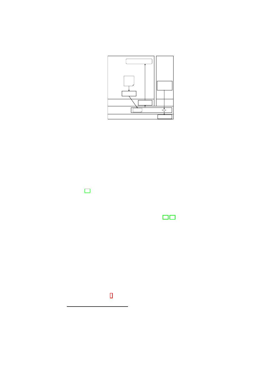
CHAPTER 10. TOWARDS DEPENDABILITY AND ATTACK RESISTANCE 139
SSVM
PVM
EHKM
Kernel
Xen
User Space
Hardware
Event Handling
Rules
Application
CPU
SCI
Rules
PIT
system
calls
The mount information gathered from the native interface query is used as the refer-
ence against which the information from the frontDoor interface is compared. If there
are mounted file systems that appear in the former but not in the latter, we take this
as an indication of a hidden malicious process because mount information is relatively
static, and hence false positives are not a big concern.
File system
In the case of the file system, bridging the semantic gap in general im-
plies the use of raw access to the physical disk and the related traffic to rebuild the
file system structures of the guest operating system of the PVM in the context of the
SSVM. Accessing file systems mounted by another operating system is feasible even
for disparate operating systems, e.g. Microsoft Windows and Linux, as for example
shown in [57]. Xen can use a Linux file system existing on the Xen/Dom0 level to boot
and launch guest domains. This same file system can then be mounted read-only by
the SSVM. We then retrieve the file information via the frontDoor and compare it with
the information of the file system mounted by the SSVM.
For efficiency and simplified forensic recording, we use a basic read-only file sys-
tem and add the CoWNFS copy-on-write file system [67, 94]. This allows us to store
the changes for multiple runs for later forensic analysis and protects the original state
of the system from any (potentially malicious) changes. This combined file system was
then used as an NFS mountable file system for booting the PVM.
10.3.4
Protection of System Integrity and Forensic Information by
means of System Call Inspection
We now outline how X-Spy’s System Call Inspection component is used to protect the
system against intrusions.
Protection of Forensic Information
In case of a successful intrusion it is highly desirable to protect as much forensic in-
formation as possible. A smart intruder would want to hide all traces of the intrusion,
e.g., by altering log-files
4
such as the
wtmp/utmp
and the
/var/log/messages
files. While these files cannot be modified by normal users, intruders with root access
4
Note that the above protection scheme for log files can easily be extended to protect other important
files, such as Xen VM configuration files, through additional rules in the rule set.
OpenTC Document D05.6/V01 – Final R7628/2009/01/15/OpenTC Public (PU)

140
OpenTC D05.6 – Final Report of OpenTC Workpackage 5
can. One way to address this issue would be to use a hardened system (e.g., SELinux).
However, this protects only if the superuser is not allowed to change the SELinux rules
in a running System.
In a virtualized environment as considered here, we have the possibility to protect
important files by intercepting the system call sequence in the PVM through the Xen
hypervisor. For this purpose, we added a module to the Xen hypervisor, the System
Call Inspector (SCI), which can inspect all
5
system calls occurring in the PVM and
either block or accept calls depending on a set of rules. These rules are stored and
edited in the SSVM (and therefore out of reach of any activity in the PVM), and can be
loaded into the SCI (in binary form) via the Policy Installation Tool (PIT).
X-Spy implements a functionality for checking and fine-tuning system calls by
instrumenting the system call handling chain. An
int 0x80
instruction is intercepted
by an interrupt handler located in the Xen context where checks against the previously
introduced rule set are done. Only after passing the checks is the call redirected to
the PVM Kernel, where the normal system call handler is invoked; otherwise, the call
returns without any action being taken. In certain cases, the system call is allowed after
some fine-tuning, e.g., a modification of the parameters so that the call conforms to the
rule set specified. The amount of performance overhead depends on the type of checks
and fine-tuning being done for a particular system call.
As the interception of the system call happens in the Xen context, the problem of
semantic gap has to be overcome to determine which system calls actually merit addi-
tional checks. For our aim of protecting forensic information, system calls performing
file operations are essential. We protect forensic information by preventing calls that
rename, link, unlink, or delete log files. Furthermore, we limit access to log files by
permitting only the append operation on them. To ensure that a malicious process
cannot bypass the checking, we normalized the paths.
If the SCI finds that an application in the PVM tries to initiate a system call that
is not allowed according to the rule set, it will block or modify it and send a corre-
sponding event through an event handling kernel module (EHKM) in the SSVM to the
high-level event handling component with information about the violated rule and the
corresponding process in the PVM.
Protection of Binaries against User-Space Rootkits
The mechanism used for protecting forensic information can also be used to protect
binaries from being altered by an intruder. Many user-space rootkits try to alter
ps
or
netstat
to hide their presence or to install a back door by modifying the
openssh
binary. While earlier tools, such as Tripwire, can detect the alteration of a binary or
a library, our event-driven approach to check system calls and their arguments can
actually prevent their alteration.
In addition, it is possible to restrict read/write access to an executable, but still allow
its execution. Based on the corresponding rule set, the module we have implemented
in the Xen hypervisor checks whether a system call is trying to change, delete, link,
or rename a binary, and if so, the call is denied. As execution of a binary normally
happens through the
execve
system call without actually opening the binary file, it
is even possible to add a rule that forbids the opening of certain binaries completely
without disallowing their execution.
5
Note that Xen implements a “fast trap” mechanism to enhance performance. If Xen calls are to be
monitored as well, then this mechanism need to be disabled.
OpenTC Document D05.6/V01 – Final R7628/2009/01/15/OpenTC Public (PU)

CHAPTER 10. TOWARDS DEPENDABILITY AND ATTACK RESISTANCE 141
Kernel Sealing
X-Spy also implements kernel sealing, a well-known method to protect a system or
prevent intrusions. The kernel memory can be accessed directly by reading or, more
dangerously, by writing to the
/dev/mem
or
/dev/kmem
device files. The rule set
of the X-Spy event-driven module in the Xen hypervisor was updated to restrict access
to those files, so that only read requests are allowed and write requests return an error
result without performing the write operation.
Accessing the kernel memory by loading a kernel module or writing directly to
/dev/(k)mem is potentially dangerous because it allows an intruder to establish its own
interface to the kernel; thereafter, the intruder can easily place malicious code in the
kernel and have full access to the file system and other kernel internals. X-Spy uses
a technique called white-listing by which all kernel modules allowed to be loaded are
explicitly specified along with their respective SHA-1 hash values. If the module to
be loaded at run-time is not specified in the white-list or if it has an incorrect hash
value, X-Spy prevents the module from being loaded by preventing the system call
from reaching the PVM kernel space. Note that our X-Spy implementation does not
offer protection against buffer overflows on systems calls.
Pre-Checking of Binaries
An effective way of protecting a PVM from user-space rootkits or other malicious
software is to check the hash of every binary, prior to its execution, against a white-list
of pre-calculated hashes and to allow its execution only if there is a match. Computing
the hash of the binary has to be done out of the reach of a potential intruder in the PVM
and should also not require modification of the PVM’s OS. To meet these conditions,
X-Spy computes the hash of the binary in the SSVM. To enable such a computation,
it is necessary that the SSVM has all partitions of the PVM mounted; furthermore, the
binary should not be on a RAM disk, on network file system, or on an encrypted file
system that the SSVM cannot access. An alternative would be to do the computation
in the hypervisor, which would require overcoming the semantic gap problem.
For computing the hash of the binary in the SSVM, we use a technique called
memory scanning, which involves loading the complete
.text
and
.data
sections
of an ELF binary into memory by setting the program counter to the next page, asking
the PVM kernel to load the page, and then hashing it while handling the page fault.
If the hash cannot be verified the hypervisor invalidates all of the memory and
returns the control back to the guest domain. Because of the invalid
.text
section
to which the PC points, the process will crash. Note that relying on support from
the PVM’s guest OS does not necessarily constitute a security gap, because a non-
cooperative PVM kernel would lead to a wrong hash value and in this case, as seen
above, the process will be forced to quit.
10.3.5
Evaluation
While the conceptual limitations have been discussed in Section 10.3.1, we will now
evaluate the effectiveness and efficiency of our implementation.
Functional Evaluation
The goal of the Lie-Detector is to expose malicious code. Once all information is
visible, we no longer focus on whether a particular LKM or process is hostile.
OpenTC Document D05.6/V01 – Final R7628/2009/01/15/OpenTC Public (PU)

142
OpenTC D05.6 – Final Report of OpenTC Workpackage 5
We first evaluated our implementation using a set of functional tests that implement
typical rootkit functionality, such as hiding processes, kernel modules, mounts, or net-
work connections. Our Lie-Detector correctly exposed all attempts to hide such critical
information.
We then tested the system using the adore-ng rootkit [107]. Adore-ng is an LKM-
based rootkit for Linux kernels which allows one to hide files and directories, processes,
and network connections. The basic rootkit consists of the kernel module and a user-
space control program. While currently this is the only widely available rootkit for
the Linux kernel 2.6, other similar rootkits exist for earlier kernel versions and may be
ported to the 2.6 kernel.
In a fully protected X-Spy system, the rootkit cannot even be installed as the in-
sertion of modules is restricted through the SCI interception of the respective system
calls and the white-listing of allowed modules. After explicitly allowing the rootkit to
insert itself into the kernel, we used its control program to hide processes, files, and net-
work connections. The X-Spy Lie-Detector component reported these hidden resources
faithfully by comparing the responses from the native and frontDoor interfaces as de-
scribed in Section 10.3.3. Although the adore-ng kernel module will remove itself from
the list of modules visible with
lsmod
, detection of the module by the Lie-Detector is
possible with the help of the shadow module list (see discussion in Section 10.3.4).
The rule set used in X-Spy’s event-driven protection mechanism contained about
110 rules, e.g. to protect forensically relevant files (e.g.
/var/log/messages
and
/var/log/wtmp
) and to prevent access to raw memory (
/dev/(k)mem)
, secu-
rity relevant configuration files (
/etc/ssh.config
), and operating system tools
(
/bin/ls
). In addition, we specified an explicit list of allowed kernel modules (mod-
ule white-listing). Once the rule set was active, it either generated security events with
information about the offending processes in the PVM or successfully prevented the
deletion or truncation of log-files and the modification of configuration and utility files.
Performance Impact
To measure the performance impact of the Lie-Detector and the event-driven ap-
proach, we used a single machine implementing a web server scenario. The PVM
hosted an Apache web server, and multiple clients were simulated using the ab
performance benchmarking tool (see
http://httpd.apache.org/docs/2.0/
programs/ab.html
). The networks were virtual and internal to this machine.
Figure 10.2(a) shows that the performance impact of the Lie-Detector depends on
how often it is run. The overhead is roughly 31% when it is running continuously, 20%
when it is run every 10 sec, and 4% when it is run every 30 sec.
Most practical applications will run infrequent scans. In this case, the performance
impact of X-Spy is negligible, particularly when compared with the performance re-
duction of moving Linux into a VM.
In a real-world setting, the frequency of “Lie Detection” should be chosen based
on the expected time until an intrusion occurs and the expected time until such an
intrusion is detected. The latter is an important factor because it denotes the critical
time window between the intrusion and its detection when the PVM is at the mercy
of the intruder, who can take arbitrary actions (such as installing a fake website or
copying private information onto a different system). If the PVM runs a critical service
in which the critical time window should be minimized, then the Lie-Detector should
be run continuously.
OpenTC Document D05.6/V01 – Final R7628/2009/01/15/OpenTC Public (PU)
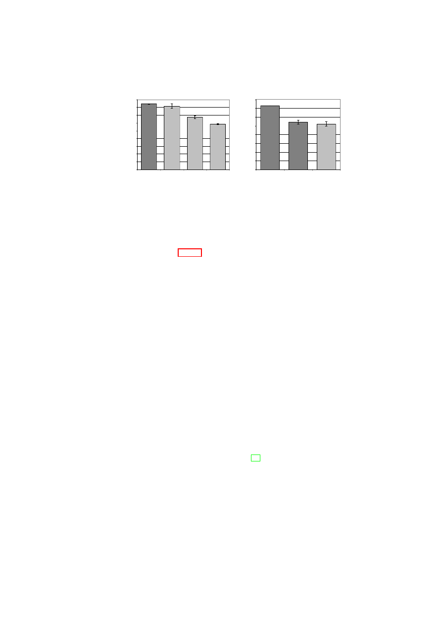
CHAPTER 10. TOWARDS DEPENDABILITY AND ATTACK RESISTANCE 143
0
100
200
300
400
500
600
700
800
900
No Lie Detection
Lie Detection
every 30s
Lie Detection
every 10s
Lie Detection
continously
R
e
q
u
e
s
ts
/s
(a) Impact of Lie-Detector
0
100
200
300
400
500
600
700
800
Linux Native
Linux Xen Unmodified
Linux Xen w ith
Event-Driven
Detection
R
e
q
u
e
s
ts
/s
(b) Impact of protective measures
Figure 10.2: Performance impact of X-Spy components: number of fulfilled requests
per second in the HTTP benchmark.
As seen in Figure 10.2(b), the event-driven method results in a performance loss
of about 4%. Compared with the 34% overhead incurred by changing from a service
running on a non-virtualized platform to that running on a Xen-based PVM, the loss
incurred by the event-driven approach is minor.
10.4
Quantifying the Impact of Virtualization on Node
Reliability
In this section, we use combinatorial modeling to perform a reliability analysis of re-
dundant fault-tolerant designs involving virtualization on a single physical node and
compare them with the non-virtualized case. The results of the analysis highlight the
importance of improving the reliability of the hypervisor.
We consider a model in which multiple VMs run concurrently on the same node
and offer identical service. We derive lower bounds on the VMM reliability and the
number of VMs required for the virtualized node in order to have better reliability
than in the non-virtualized case. We also analyze the reliability impact of moving a
functionality common to all VMs out of the VMs and into the VMM. In addition, we
analyze the reliability of a redundant execution scheme that can tolerate the corruption
of one out of three VMs running on the same physical host, and compare it with the
non-virtualized case. Our results point to the need for careful modeling and analysis
before a design based on virtualization is used.
Combinatorial modeling and Markov modeling are the two main methods used for
reliability assessment of fault-tolerant designs [58]. We chose combinatorial modeling
because its simplicity enables easy elimination of “hopeless” choices in the early stage
of the design process. In combinatorial modeling, a system consists of series and paral-
lel combinations of modules. The assumption is that module failures are independent.
In a real-world setting, where module failures may not be independent, the reliability
value obtained using combinatorial modeling should be taken as an upper bound on the
system reliability.
Non-Virtualized (NV) Node: For our reliability assessment, we consider a non-
virtualized single physical node as the base case. We model the node using two mod-
OpenTC Document D05.6/V01 – Final R7628/2009/01/15/OpenTC Public (PU)
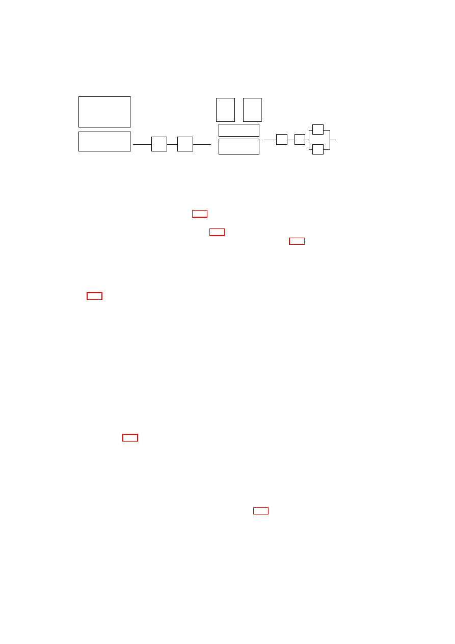
144
OpenTC D05.6 – Final Report of OpenTC Workpackage 5
Hardware H
OS + Application
M
(a) Architecture
H
M
(b) Combinatorial Model
Figure 10.3: Non-virtualized node
. . .
Hardware H
Virtual
Machine
M
n
Virtual
Machine
M
1
Virtual Machine
Monitor V
(a) Architecture
n
M
M
.
.
.
H
V
1
(b) Combinatorial Model
Figure 10.4: Node with
n
VMs
ules: hardware (
H
) and the software machine (
M
) consisting of the operating system,
middleware, and applications (Figure 10.3(a)) . Thus, the node is a simple serial sys-
tem consisting of
H
and
M
, whose reliability is given by
R
N V
sys
=
R
H
R
M
, where
R
X
denotes the reliability of module
X
(Figure 10.3(b)).
Virtualized Node with
n
Independent, Identical VMs: Figure 10.4(a) shows a
physical node consisting of
H
, a type-1 VMM (
V
) that runs directly on the hardware
(such a VMM is referred to as a hypervisor), and one or more VMs (
{
M
i
}
, i
≥
1
). The
VMs provide identical service concurrently and independently (i.e., without the need
for strong synchronization). For example, each VM could be a virtual server answering
client requests for static web content. Thus, the node is a series-parallel system (Fig-
ure 10.4(b)) whose overall reliability is given by
R
n
sys
=
R
H
R
V
[1
−
Q
n
i
=0
(1
−
R
M
i
)]
.
Here, we consider the reliability of the hardware to be the same as that in the non-
virtualized case because the underlying hardware is the same in both cases. An obvious
concern is whether the hardware in the virtualized node will register a significant drop
in reliability due to load/stress compared with the non-virtualized node. However, this
concern does not apply to our context of application servers in a data center, in which
typical hardware utilization in a non-virtualized node is abysmally low (less than 5%)
and
n
is typically in the low tens of VMs.
The condition for the
n
-replicated service to be more reliable than the non-
virtualized service is given by
R
n
sys
> R
N V
sys
. i.e.,
R
H
R
V
[1
−
Q
n
i
=0
(1
−
R
M
i
)]
>
R
H
R
M
. For simplicity, let
R
M
i
=
R
M
for all
1
≤
i
≤
n
. This is a reasonable as-
sumption, as each VM has the same functionality as the software machine
M
in the
non-virtualized case. Then, the above condition becomes
R
V
[1
−
(1
−
R
M
)
n
]
> R
M
.
(10.1)
Inequality (10.1) immediately yields two conclusions. First, if
n
= 1
, then again
the above condition does not hold (
R
V
<
1
). What this means is that it is necessary
to have some additional coordination mechanism or protocol built into the system to
compensate for the reliability lost by the introduction of the hypervisor. In the absence
of such a mechanism/protocol, simply adding a hypervisor layer to a node will only
decrease node reliability. Second, if
R
V
=
R
M
, then it is obvious that above condition
does not hold.
It is clear that the hypervisor has to be more reliable than the individual VMs. The
interesting question is how much more reliable. Figure 10.5 shows that for a fixed
R
M
value, the hypervisor has to be more reliable when deploying fewer VMs. The
graph also shows that, for fixed values of
R
M
and
R
V
, there exists a lower bound on
n
below which the virtualized node reliability will definitely be lower than that of a
non-virtualized node. For example, when
R
M
= 0.1 and
R
V
= 0.3, deploying fewer
OpenTC Document D05.6/V01 – Final R7628/2009/01/15/OpenTC Public (PU)
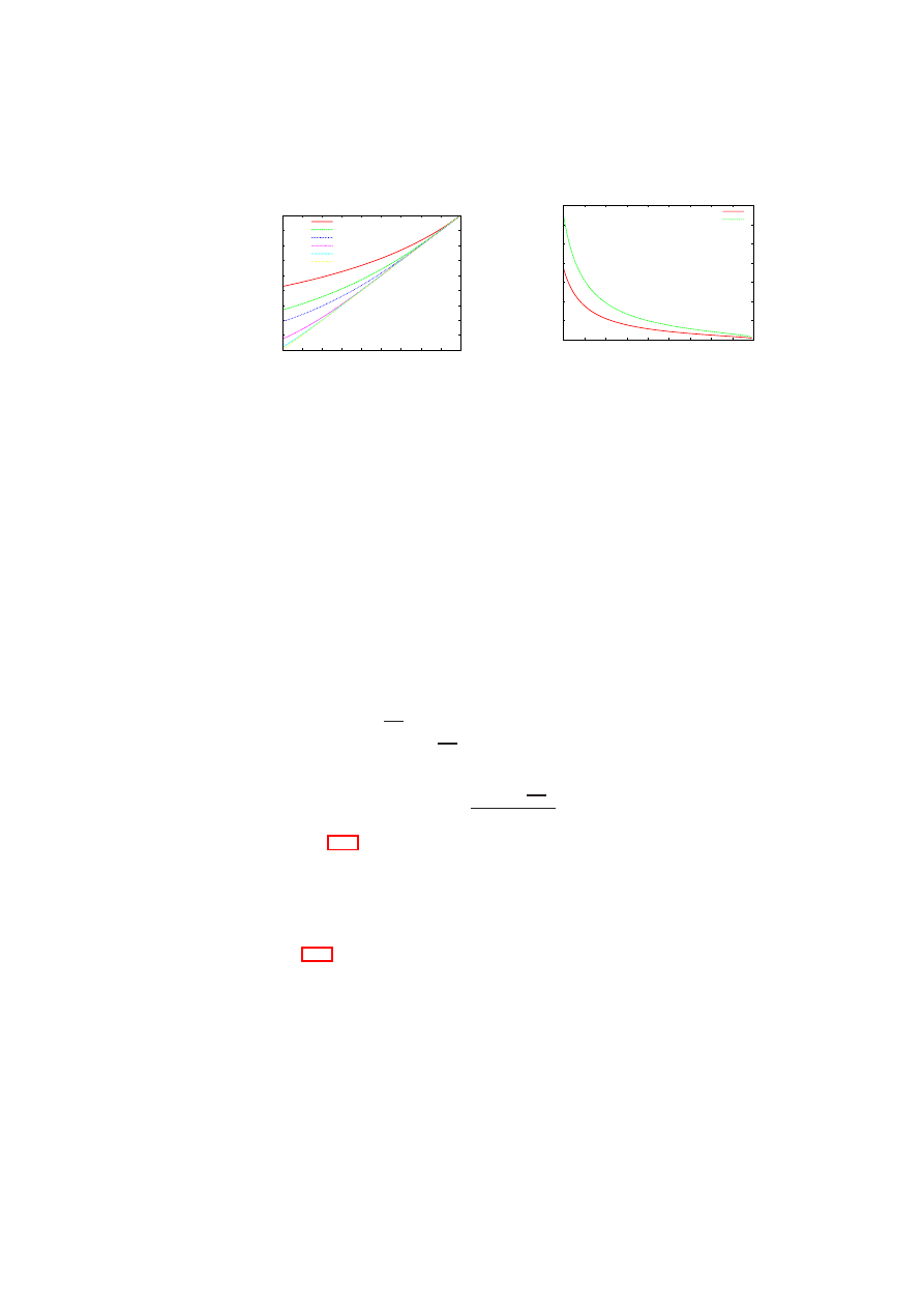
CHAPTER 10. TOWARDS DEPENDABILITY AND ATTACK RESISTANCE 145
0.1
0.2
0.3
0.4
0.5
0.6
0.7
0.8
0.9
1
0.1 0.2 0.3 0.4 0.5 0.6 0.7 0.8 0.9
1
Lower Bound on Reliability
of Hypervisor (R
V
)
Reliability of Virtual Machine (R
M
)
n=2
n=3
n=4
n=8
n=16
n=32
Figure 10.5: Lower bound on the hy-
pervisor reliability for a physical node
with
n
independent and concurrently
operating VMs providing identical ser-
vice.
0
10
20
30
40
50
60
70
0.1
0.2
0.3
0.4
0.5
0.6
0.7
0.8
0.9
1
Lower Bound on Number of VMs (n)
Reliability of Virtual Machine (R
M
)
R = 0.98
R = 0.998
Figure 10.6: Lower bound on the num-
ber of VMs to achieve desired reliabil-
ity
R
for a physical node with
n
in-
dependent and concurrently operating
VMs providing identical service when
R
V
= 0
.
999
.
than 4 VMs would only lower the node reliability. This is a useful result, as in many
practical settings,
R
M
and
R
V
values may be fixed, e.g., when the hypervisor, guest
OS, and application are commercial off-the-shelf (COTS) components with no source-
code access.
The equation for
R
n
sys
also suggests that by increasing the number of VMs, the node
reliability can be made as close to the hypervisor reliability as desired. Suppose we
desire the node reliability to be
R
, where
R < R
V
. Then,
R
=
R
H
R
V
[1
−
(1
−
R
M
)
n
]
.
Assume that the hardware is highly reliable, i.e.,
R
H
≃
1
. Then, the above equation
becomes the inequality,
R < R
V
[1
−
(1
−
R
M
)
n
]
=
⇒
(1
−
R
M
)
n
<
1
−
R
R
V
=
⇒
n.
log(1
−
R
M
)
<
log(1
−
R
R
V
)
Dividing by
log(1
−
R
M
)
, a negative number, we obtain,
n >
log(1
−
R
R
V
)
log(1
−
R
M
)
.
(10.2)
Inequality (10.2) gives a lower bound on the number of VMs required for a virtu-
alized physical node to meet a given reliability requirement. In practice, the number
of VMs that can be hosted on a physical node is ultimately limited by the resources
available on that node. Comparing the lower bound with the number of VMs that can
possibly be co-hosted provides an easy way of eliminating certain choices early in the
design process.
Figure 10.6 shows the lower bound for
n
for two different
R
values (0.98 and
0.998) as the VM reliability (
R
M
) is increased from roughly 0.1 to 1.0, with the hyper-
visor reliability fixed at
0
.
999
. The figure shows that for fixed
R
V
and
R
M
values, a
higher system reliability (up to
R
V
) can be obtained by increasing the number of VMs
hosted. However, when
n
is large, one is faced with the practical difficulty of obtaining
sufficient diversity to ensure that VM failures are independent.
Moving Functionality out of the VMs into the Hypervisor: We now analyze the
reliability impact of moving a functionality out of the VMs and into the hypervisor.
As before, our system model is one in which a physical node has
n
≥
1
independent
OpenTC Document D05.6/V01 – Final R7628/2009/01/15/OpenTC Public (PU)
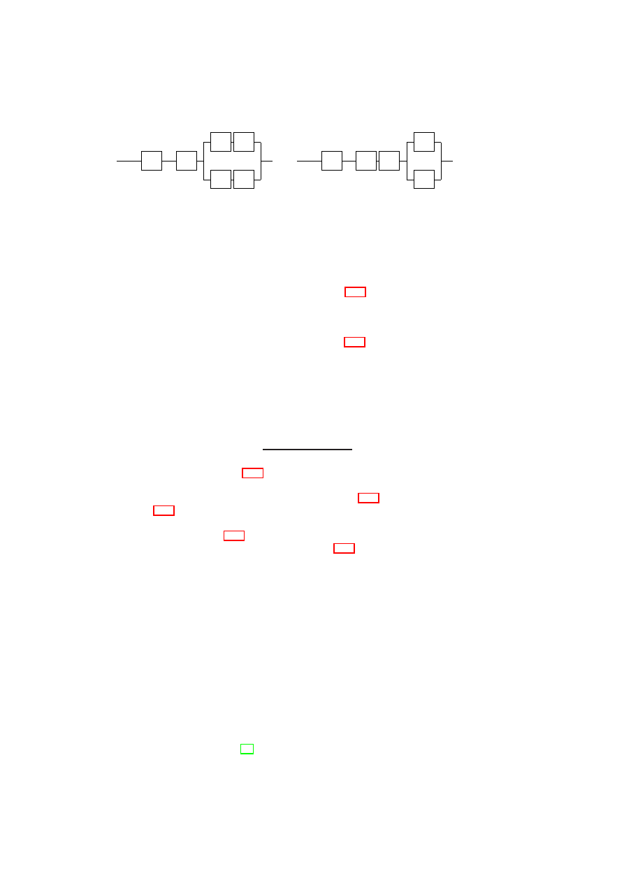
146
OpenTC D05.6 – Final Report of OpenTC Workpackage 5
’
M
1
.
.
.
H
V
f
f
M
n
’
(a) Configuration
C
1
: Functionality
f
imple-
mented within each VM
’
M
1
.
.
.
H
V
M
n
F
’
(b) Configuration
C
2
: Functionality
F
imple-
mented as part of Hypervisor
Figure 10.7: Moving functionality out of the VMs into the hypervisor
and concurrently operating VMs providing identical service. Consider a functionality
f
implemented inside each VM. Then, each VM
M
i
can be divided into two components,
f
and
M
′
i
, the latter representing the rest of
M
i
. Figure 10.7(a) shows the reliability
model for a node containing
n
such VMs. Let us call this node configuration
C
1
.
Further, suppose that the functionality
f
is moved out of the VMs and substituted by
component
F
implemented as part of the hypervisor. Now, the new hypervisor consists
of two components
F
and the old hypervisor
V
. Figure 10.7(b) shows the reliability
model for a node with the modified hypervisor. Let us call this node configuration
C
2
.
We now derive the condition for
C
2
to be at least as reliable as
C
1
. For simplicity,
let us assume that
R
M
′
i
=
R
M
′
for all
1
≤
i
≤
n
. Then, the desired condition is
R
C
2
sys
≥
R
C
1
sys
=
⇒
R
H
R
V
R
F
[1
−
(1
−
R
M
′
)
n
]
≥
R
H
R
V
[1
−
(1
−
R
f
R
M
′
)
n
]
=
⇒
R
F
≥
[1
−
(1
−
R
f
R
M
′
)
n
]
[1
−
(1
−
R
M
′
)
n
]
.
(10.3)
It is easy to see from Figure 10.7 that if there is only one VM, it does not matter
whether the functionality is implemented in the hypervisor or in the VM. We can also
confirm this observation by substituting
n
= 1
in inequality (10.3).
Figures 10.8(a) and (b) illustrate how
R
F
varies as
R
f
is increased from 0.1 to 1.
The graphs show that for configuration
C
2
to be more reliable than
C
1
,
F
has to be
more reliable than
f
. Figure 10.8(a) shows that as
R
M
′
increases, the degree by which
F
should be more reliable than
f
also increases. Figure 10.8(b) shows that the degree is
also considerably higher when more VMs are co-hosted on the same physical host. For
example, even with modest
R
M
′
and
R
f
values of 0.75,
F
has to be ultra-reliable:
R
F
has to be more than 0.9932 and 0.9994 if
n
= 6
and
n
= 9
, respectively. Thus, when
more than a handful of VMs are co-hosted on the same physical node, a better system
reliability is more likely to be obtained by retaining a poorly reliable functionality in
the VM rather than by moving the functionality into the hypervisor.
Virtualized Node with VMM-level Voting: Consider a fault-tolerant 2-out-of-3
replication scheme in which three VMs providing identical service are co-hosted on a
single physical node. The VMM layer receives client requests and forwards them to all
three VMs in the same order. Assume that the service is a deterministic state machine;
thus, the VM replicas yield the same result for the same request. The VMM receives the
results from the VM replicas. Once the VMM has obtained replies from two replicas
with identical result values for a given client request, it forwards the result value to
the corresponding client. Such a scheme can tolerate the arbitrary failure of one VM
replica, and is similar to the one suggested in the RESH architecture for fault-tolerant
replication using virtualization [92]. Assuming that the VMs fail independently, the
OpenTC Document D05.6/V01 – Final R7628/2009/01/15/OpenTC Public (PU)
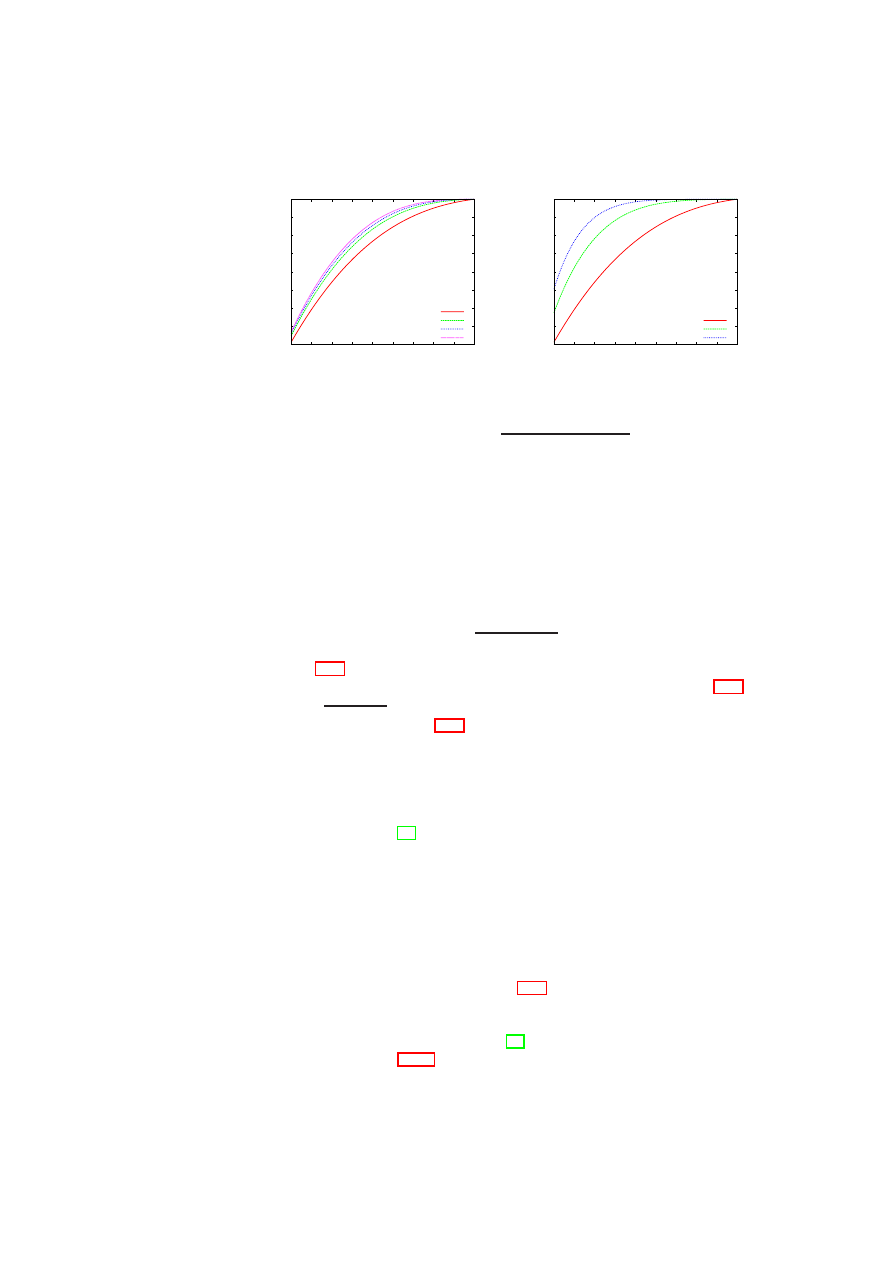
CHAPTER 10. TOWARDS DEPENDABILITY AND ATTACK RESISTANCE 147
0.2
0.3
0.4
0.5
0.6
0.7
0.8
0.9
1
0.1 0.2 0.3 0.4 0.5 0.6 0.7 0.8 0.9
1
Lower Bound on Reliability
of Functionality when
Moved to Hypervisor (R
F
)
Reliability of Functionality Implemented in VM (R
f
)
R
M’
= 0.75, n = 3
R
M’
= 0.90, n = 3
R
M’
= 0.95, n = 3
R
M’
= 0.99, n = 3
(a) Fixed
n
, varying
R
M
′
0.2
0.3
0.4
0.5
0.6
0.7
0.8
0.9
1
0.1 0.2 0.3 0.4 0.5 0.6 0.7 0.8 0.9
1
Lower Bound on Reliability
of Functionality when
Moved to Hypervisor (R
F
)
Reliability of Functionality Implemented in VM (R
f
)
R
M’
= 0.75, n = 3
R
M’
= 0.75, n = 6
R
M’
= 0.75, n = 9
(b) Fixed
R
M
′
, varying
n
Figure 10.8: Plot of
R
F
≥
[1
−
(1
−
R
f
R
M
′
)
n
]
[1
−
(1
−
R
M
′
)
n
]
system reliability is given by
R
2
−
of
−
3
sys
=
R
H
R
V
[
R
3
M
+
3
2
R
2
M
(1
−
R
M
)]
.
Then,
R
2
−
of
−
3
sys
> R
N V
sys
gives the condition for the 2-out-of-3 replication scheme to be
more reliable than the non-virtualized service. Thus, we obtain
R
H
R
V
[
R
3
M
+
3
2
R
2
M
(1
−
R
M
)]
> R
H
R
M
=
⇒
R
V
>
1
3
R
M
−
2
R
2
M
.
(10.4)
Inequality (10.4) gives a lower bound on the hypervisor reliability for the 2-out-of-3
replication scheme to have better reliability than the non-virtualized case. Figure 10.9
shows a plot of
1
3
R
M
−
2
R
2
M
< R
V
<
1
. It is clear from the graph that there exists no
R
V
value that satisfies inequality (10.4) and is less than 1 when
R
M
≤
0
.
5
. In other
words, if the VM reliability (i.e., the operating system and service reliability) is poor to
begin with, then the 2-out-of-3 replication scheme will only make the node reliability
worse even if the hypervisor is ultra-reliable. This result concurs with the well-known
fact that any form of redundancy with majority voting is not helpful for improving over-
all system reliability when the overall system is composed of modules with individual
reliabilities of less than
0
.
5
[58]. The graph also shows that the higher the hypervisor
reliability, the larger the range of VM reliability values for which the 2-out-of-3 repli-
cation scheme has better reliability than the non-virtualized case. For example, when
R
V
= 0
.
98
, the range of VM reliability values that can be accommodated is greater
than the range when
R
V
= 0
.
9
.
10.5
An Architecture for a More Reliable Xen VMM
As shown by the model-based analysis in Section 10.4, it is highly desirable to make the
VMM as reliable as possible to improve the overall reliability of a virtualized node. In
this section, we leverage our X-Spy implementation to propose a reliability-enhanced
design of the popular Xen open-source VMM [11].
The Xen VMM (Figure 10.10(a)) consists of a hypervisor core and a privileged
domain (or VM) called Dom0 or domain zero. The hypervisor core is small in size and
OpenTC Document D05.6/V01 – Final R7628/2009/01/15/OpenTC Public (PU)
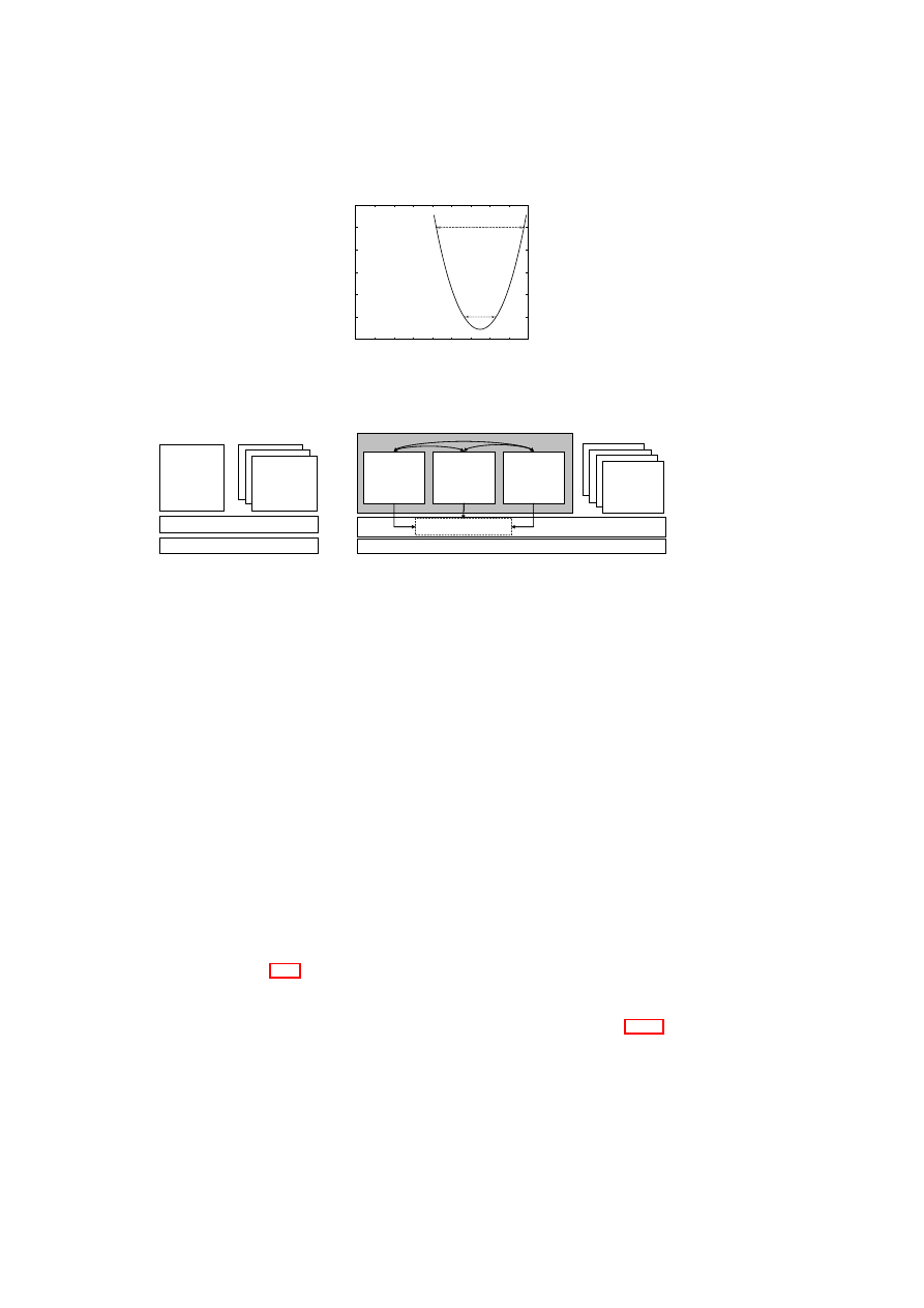
148
OpenTC D05.6 – Final Report of OpenTC Workpackage 5
0.88
0.9
0.92
0.94
0.96
0.98
1
0.1 0.2 0.3 0.4 0.5 0.6 0.7 0.8 0.9
1
Lower Bound on Reliability
of Hypervisor (R
V
)
Reliability of Virtual Machine (R
M
)
Figure 10.9: Plot of
(3
R
M
−
2
R
2
M
)
−
1
< R
V
<
1
Physical Hardware
Management
of VMs,
Virt. Devices,
and security
Dom0
Xen Hypervisor
User domains
(a) Normal Xen Architecture
Physical Hardware
R-Dom0
User domains
Xen Core
Dom0.A
Dom0.B
Dom0.C
mutual intrusion
monitoring
periodic intrusion reports
Leader Selection, Trust Vote,
Termination, and Rejuvenation
(b) R-Xen Architecture
Figure 10.10: Enhancing the Reliability of the Xen VMM
concerned with virtualizing the memory and CPU. Dom0 is a full-fledged VM running
a guest OS (Linux) and virtualizes other hardware devices (such as disks and network
interfaces). Dom0 is the first domain that is created, and controls all other domains,
called user domains or DomUs. For any given physical device in Xen, the native device
driver is part of at most one VM. If the device is to be shared with other VMs, then the
VM with the native device driver makes the device available through a back-end driver.
Any VM that wants to share the device exports a virtual device driver called the front-
end driver to the back-end driver. Every front-end virtual device has to be connected to
a corresponding back-end virtual device; only then does the front-end device become
active. The mapping is one-to-one, i.e., each front-end virtual device from each user
domain is mapped to a corresponding back-end virtual device. The communication
between the back-end and front-end drivers takes places through shared memory and
event channels. The event channel is used for sending simple lightweight notifications
and the shared memory is used for sending requests and data.
As Dom0 is relatively large, we expect its reliability to be lower than that of the
hypervisor core. Thus, improving the reliability of Dom0 is crucial to improving the
reliability of the Xen VMM as a whole. We combine some of the technologies de-
scribed in Section 10.2, namely, intrusion detection, enforcing fail-stop behavior, and
intrusion response in form of software rejuvenation, to architect a more reliable Xen
VMM, which we call R-Xen.
In R-Xen, we enhance the reliability of Dom0 by replication (Figure 10.10(b)).
Dom0 is a single logical entity that actually consists of three privileged domains,
Dom0.A, Dom0.B, and Dom0.C, with identical privilege levels. The three replicas
mutually monitor each other using the techniques we described above in our X-Spy
implementation. Specifically, each Dom0 replica is simultaneously the PVM and the
OpenTC Document D05.6/V01 – Final R7628/2009/01/15/OpenTC Public (PU)

CHAPTER 10. TOWARDS DEPENDABILITY AND ATTACK RESISTANCE 149
SSVM for the other two Dom0s. Periodically, the Dom0 replicas submit a fault detec-
tion vote to the hypervisor core that indicates whether one of its two peers is thought to
be compromised. If any given Dom0 replica is labeled as being faulty by its two peer
SSVMs, then the replica will be terminated and rejuvenated by the hypervisor. In this
way, we enforce fail-stop behavior of the replica despite the presence of a more severe
kind of fault in the replica. The hypervisor core then starts a new Dom0 replica as a
replacement of the terminated one.
One of the Dom0 replicas is designated as active by the hypervisor core, and it is
this active replica that provides the back-end drivers for the devices of the user domains.
The other two replicas are designated as passive, and do not provide any back-end de-
vices. As mentioned above, each of the three Dom0 replicas monitors and is being
monitored by the other two. If the hypervisor gets reports from two independent repli-
cas labeling the third replica as faulty, then the hypervisor terminates that replica and
replaces it with a new Dom0 replica. If the terminated replica is a primary, then the
hypervisor designates one of the backups as the new primary replica by re-connecting
the front-end devices of the user domain(s) to the replica’s back-end devices. The dis-
connection and reconnection of the user domain(s) to a different Dom0 has already
been implemented in Xen and is used for live migration of domains. Therefore, the
code can be reused. The hypervisor itself has to actively give permissions for doing
the reconnection and re-routing the data from the old Dom0 to the new one. It also has
to shutdown the old Dom0 after the reconnection process has been completed. Using
a previously started backup as the new primary results in less interruption to the user
domain than using the replacement replica (which has to be booted from scratch) as the
new primary. It also enables the booting of the replacement replica to occur concur-
rently to the re-connection of the front-end devices. Like other fault-detection-based
techniques, there is the drawback of detection latency, i.e., a time delay between the
actual occurrence of the fault and its detection. I/O requests sent by the user domain(s)
during this latency period may have to be re-issued. On the positive side, our technique
can be implemented in a manner that is completely transparent to the user domain(s).
In other words, a DomU running on normal Xen should be able to run without modifi-
cation on this type of R-Xen as well.
OpenTC Document D05.6/V01 – Final R7628/2009/01/15/OpenTC Public (PU)

150
OpenTC D05.6 – Final Report of OpenTC Workpackage 5
OpenTC Document D05.6/V01 – Final R7628/2009/01/15/OpenTC Public (PU)

Part III
Evaluation and Outlook
151

Chapter 11
Security Management
Components of the OpenTC
Virtual Datacenter Prototype
11.1
Overview
We realized a prototype of a physical data center implementing multi-tenant virtual data
centers. Each one, usually owned by a different customer, is mapped onto a different
TVD.
Our prototype is based on two classes of building blocks: Physical hosts providing
VMs for the virtual domains and hosts running the data center services.
Figure 11.1 shows a host of the first class, a single secure hypervisor platform (that
we henceforth refer to as “the platform”) that is based on the Xen architecture [11]
(Xen 3.1.1 and Linux kernel 2.6.22). Following the Xen model, the platform consists
of a core hypervisor, the privileged management VM called Domain-0, and the guest
VMs. We have also implemented the TVD Master role that runs on a second class host
and maintains policies and membership for a given virtual domain.
The following components are provided by our platform. The Compartment Man-
ager manages the life-cycle and the integrity of the guest VMs (also called compart-
ments
1
). The TVD Proxy is the local representative of the TVD Master running on
the platform and enforcing the policies of that TVD. Each TVD Proxy is created and
spawned by a TVD Proxy Factory, whenever a TVD needs to be extended to a new
host. The Secure Virtual Network subsystem creates, manages, and makes secure the
virtual LAN for each TVD. The Trusted Channel Proxy implements the Trusted Chan-
nel needed for the pre-admission phase. In the current implementation, all these com-
ponents run in Domain-0. Together with the Xen hypervisor and the other services in
Domain-0, they constitute the Trusted Computing Base (TCB) of the platform, i.e., the
integrity of these components must be ensured to guarantee the correct enforcement of
the TVD policies.
The integrity measurements of the TCB components are performed during the au-
1
A compartment is a protected execution environment, subject to information flow control policies en-
forced by the hypervisor: a compartment can securely host a single process running with threads as well as
full-fledged VMs.
152
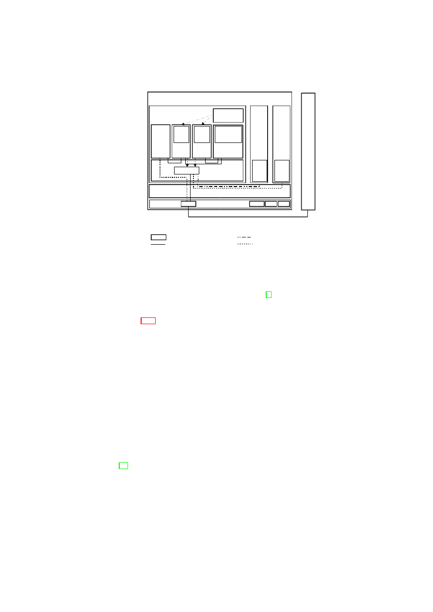
CHAPTER 11. SECURITY MANAGEMENT DEMONSTRATOR
153
Dom0 Compartment
(Privileged VM)
Xen Hypervisor
Hardware
CRTM CPU TPM
Component Forming the TCB
Linux Kernel
Trusted
Channel
Proxy
TVD A
Proxy
Compartment
Manager
NIC
VNET
VM:
Dom1,
TVD A
TVD
Policy
Engine
Local
Policy
Engine
Linux
Kernel
VM:
Dom2,
TVD B
Linux
Kernel
Platform providing VMs to TVDs
Legend:
Control Flow Channel
TVD A Data Flow
TVD B Data Flow
T
V
D
M
a
s
te
r
TVD Proxy
Factory
TVD B
Proxy
TVD
Policy
Engine
Figure 11.1: Xen Architecture for TVD.
thenticated boot, when the chain of trust begun by the Core Root of Trust for Mea-
surement (CRTM) is extended using TrustedGRUB [4], a TCG-enhanced version of
the standard GRUB boot loader. The TVD Master implements one end of the Trusted
Channel establishment protocol. The other end is the TVD Proxy Factory.
Figure 11.2 shows the simplified layout of our prototype data center. It has two
virtual networks per customer: a management network for managing the customer’s
VMs within the TVD and a user data network for the actual communication between
client VMs. Furthermore, the data center has a DMZ for external connections, a virtual
data center management network (VDC) that is used for communication between our
data center management components, and finally a SAN network that provides storage
to the individual platforms.
Each virtual domain has a intra-domain management VM that runs the management
software of the customer and connects to the management network. This management
software interacts with a filtered XenAPI (called XenAPI’) that hides infrastructure and
machines belonging to other virtual domains and provides a virtual view of the data
center. Each administrator in a virtual domain can then define and start any number of
guest VMs that get connected to the corresponding data network.
11.2
Security Services
In [55], we have described a Xen-based prototype of our security services for integrity
management and obtaining compliance proofs. The prototype enables the protection
of security policies against modification and allows stakeholders to verify the poli-
cies actually implemented. The paper also describes multiple use cases, in which we
demonstrated the policy enforcement and compliance-checking capabilities of our im-
plementation. For example, we showed how to validate the configuration of the virtual
networking subsystem on each host (assuming that a TPM is embedded in each host).
OpenTC Document D05.6/V01 – Final R7628/2009/01/15/OpenTC Public (PU)
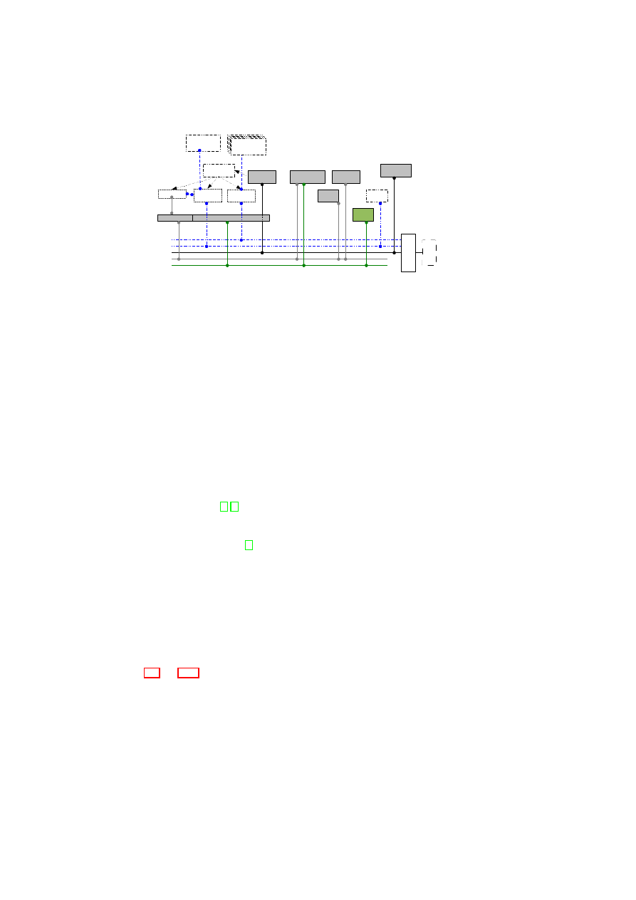
154
OpenTC D05.6 – Final Report of OpenTC Workpackage 5
VDC
SAN
DMZ
TVDdata
TVDmgn
TVDproxy
Factory
TVDproxy
vSwitch
(mgnt.)
vSwitch
(data)
XenAPI
XenAPI'
Xen
DC Host Platform
TVD
Master
F
ire
w
a
ll
In
te
rn
e
t
DHCP
Server
PXEboot
Server
DC infrastructure components
SAN/
NFS
Guest
NFS
Intra-TVD
Mgmt. VM
TVD Guest
VMs
VDC mgnt.
Server
TVD Guest
VMs
TVD Guest
VMs
TVD Guest
VMs
NOTE: dashed lines denote connections that are internal to the virtual domain
Figure 11.2: Layout of our prototype virtual data center.
Here, we provide an overview of our security services implementation. The Com-
partment Manager (CM) is responsible for the VM life-cycle management. As the
sole entry point for VM-related user commands, it communicates directly with the
hypervisor and orchestrates the Integrity Manager and the secure device virtualization
functions of the platform. These functions base on the standard Xen management tools.
The CM through the Integrity Manager (IM) is responsible for verifying the in-
tegrity of the VMs. The root file system is made available to each VM, including
Domain-0, through a pair of partitions or virtual disks. One of them is read-only, con-
tains the initial root file system, and is measured together with the VM configuration
file; the resulting whole integrity measurement of the VM is then accumulated into the
TPM by extending one PCR. The other partition or virtual disk, which is read/write
and empty at the beginning of the VM life, records the changes occurring on the root
file system while the VM is running. This is done through the copy-on-write mecha-
nism provided by unionfs [5, 1] which allows the stacking of multiple file systems and
provides the operating system with a unified view. CM and IM are also responsible for
guaranteeing the confidentiality of a VM’s data (stored on the second read/write image)
by encrypting it using dm-crypt [2], which is the Linux device mapper with support for
encrypting block devices (e.g. physical or virtual disks and partitions). Next, the en-
cryption key is sealed against the measurement of the TCB and of the VM (stored in
a set of PCRs). We use this “sealed disk” scheme to protect the VM’s confidential
data. This scheme can be applied to all disks, except the root image, depending on the
security requirements given.
The TVD policy defines, for each VM, the disks that need to be measured, the
PCR(s) in which the measurements need to be stored, and the disks that need to be
sealed.
Once the policy has been executed and all disks have been prepared (mea-
sured/unsealed), the admission protocol involving the CM and the TVD Proxy (see
Sections 3.4 and 11.3) follows. Then the CM requests Xen to start the VM. To manage
VMs, the CM maintains the association between a running VM and the policy that was
used to start it.
OpenTC Document D05.6/V01 – Final R7628/2009/01/15/OpenTC Public (PU)

CHAPTER 11. SECURITY MANAGEMENT DEMONSTRATOR
155
11.3
TVD Master, Proxies and Proxy Factories
The TVD policy of our prototype lists all VMs that can potentially be admitted to the
TVD. Each VM is identified by the Xen domain identifier. For each VM, the policy
specifies the required integrity measurement value. Only if the VM’s actual measure-
ment value (obtained by the CM) matches the required value the VM will be admitted
to the TVD. The policy also specifies the MAC address assigned to the VM’s virtual
NIC, if the admission is successful. Moreover, it identifies the VLAN corresponding
to the TVD, and the VPN keys needed for establishing secure connections within the
TVD. Currently one shared key per TVD is used to protect all insecure links.
When a VM wants to be admitted to the TVD (i.e., this is stated in the configuration
file of the VM), the related TVD Proxy is contacted by CM using a stateless TCP-
based protocol called Compartment Admission Protocol (CAP). Since a platform can
host VMs belonging to different TVDs, the CM contacts the TVD Proxy Factory to
obtain the TVD Proxy end-point for the requested TVD. If such TVD Proxy is not
running yet, the TVD Proxy Factory creates and spawns it. Before starting the VM,
CM measures it (as explained in Section 11.2) and asks the TVD Proxy whether the
VM can be admitted to the TVD by passing the identifier and the measurement of the
VM. If the answer is positive, CM receives the MAC address specified in the policy
from the TVD Proxy, creates the back-end network device (see Section 11.4 for further
explanations about Xen back-end and front-end devices), and sets the MAC address
for the front-end device. Finally, the CM requests the TVD Proxy to attach the VM to
the virtual switch (vSwitch) of the VLAN corresponding to the TVD by specifying the
identifier, measurement value, and the names of back-end devices for the VM being
admitted. In the case of a negative response from the TVD Proxy, the CM can be
configured to either start the VM even though it will not be connected to the TVD
VLAN or not to start it at all.
11.4
Secure Virtual Network subsystem
The prototype implementation of our Secure Virtual Network subsystem has been doc-
umented in [18] and has been integrated in the prototype being presented in this paper.
Our networking extensions consist of vSwitches, VLAN tagging, and LAN encapsula-
tion modules. They are implemented as kernel modules in Domain-0, which also acts
as the driver VM for the physical NIC(s) of each physical host.
To specify the particular vSwitch and the particular port in the vSwitch to which a
VM’s Xen back-end device must be attached, the Xen VM configuration file is used.
This file is generated by CM after having received information (MAC address and
VLAN identifier) from the TVD Proxy. We use additional scripts to specify whether
a particular vSwitch should use one or both of the VLAN tagging and encapsulation
mechanisms for isolating separate virtual networks.
The vSwitches maintain a table mapping virtual network devices to ports on a par-
ticular vSwitch. The encapsulation module implements EtherIP processing for packets
coming out of and destined for the VMs. The VLAN segments associated with dif-
ferent TVDs and the corresponding vSwitches are assigned unique identifiers. The
network identifier field in the EtherIP packets is set to the identifier of the vSwitch that
the target VM is attached to.
The VLAN tagging module tags the packet with the VLAN identifier corresponding
to the VLAN that the target VM is a part of. At the destination platform, the VLAN
OpenTC Document D05.6/V01 – Final R7628/2009/01/15/OpenTC Public (PU)

156
OpenTC D05.6 – Final Report of OpenTC Workpackage 5
module removes the VLAN tags, and routes the packets to the appropriate vSwitch
based on the VLAN tag.
11.5
Trusted Channel Proxies
The Trusted Channel between TVD Proxy Factory and TVD Master used during the
pre-admission phase is set up by means of a pair of services called Trusted Channel
proxies. They implement the Trusted Channel at the application layer via a TLS tun-
nel, made available to TVD Proxy Factory and Master once remote attestation has been
successful. The remote attestation is done by performing the
TPM_Quote
operation,
namely, digitally signing a set of PCRs and a challenge received from the remote at-
tester using a TPM asymmetric key. The latter can be certified as Attestation Identity
Key (AIK) by a Privacy CA. The result of the
TPM_Quote
operation (i.e. the signature
over a set of PCR values), the actual PCR values and the AIK Public Key Certificate
are sent by the TVD Proxy Factory to the TVD Master to be verified. If the verifi-
cation is successful, then the remote attestation can be considered successful, and the
two proxies start tunneling the incoming TCP packets through the TLS channel. An
alternative implementation for attesting via Trusted Channel is documented in [9] and
will be integrated in our prototype. This approach replaces the
TPM_Quote
operation
with the usage of sealing and TPM certified keys.
OpenTC Document D05.6/V01 – Final R7628/2009/01/15/OpenTC Public (PU)

Chapter 12
Evaluation of the Prototype
12.1
Performance Evaluation
We implemented our data center prototype using HP ProLiant BL25p G2 blade servers
each fitted with two AMD Opteron processors running at 2 GHz, 8GB system memory
and a Gigabit Ethernet card. We now discuss the performance of our prototype. Most
of our components implement or support management tasks. They are dedicated to
automate the secure set-up of platforms, virtual machines and domains, if possible
with minimal performance impact on the running system.
Note that measuring performance of virtual systems is not straightforward. We
first used
iostat
to retrieve CPU usage data from
/proc/stat
under Linux and
in Domain-0. This wrongly indicated that Xen needs half the CPU as compared to
Linux. We then used the Xen tool
xentop
that gathers the data via hyper-calls to the
hypervisor. Since this represents the time given to each VM (Domain-0, guest VM) by
the hypervisor, the resulting data was no longer distorted by the virtual notion of time
given to the VMs in Xen.
12.1.1
Management
In Table 12.1 compares the boot-up and shut-down delay between for virtual machines
using the unmodified Xen implementation and our components. Averaged over 235
measurements, our components add some 10 percent to the the original time-to boot.
The delay is caused by measuring the configuration, attesting to the VM, transferring
and checking configuration measurements, and (in case of success) attaching the VM
to the corresponding network. Stopping a virtual machine requires 2.4s instead of 0.5s
for the original Xen implementation. Here, the overhead is caused by the fact that
the current implementation of the compartment manager polls the VM in rather long
intervals to verify a successful shut-down.
System Measured
Operation
Prototype
Xen
Management
Start
3.601s
3.332s
Stop
2.371s
0.460s
Table 12.1: Performance Measurements of our Prototype
157
158
OpenTC D05.6 – Final Report of OpenTC Workpackage 5
Throughput
Linux
VLAN Tagging
Xen Bridging
EtherIP
TX (Mbps)
932
883
872
847
RX (Mbps)
932
881
870
851
Comparison
100%
56.79%
55.98%
54.69%
Table 12.2: NetPerf Benchmark: Guest VM to Guest VM Throughput.
Minimum
Average
Maximum
Mean Deviation
Bridged
0.136s
0.180s
0.294s
0.024s
VLAN
0.140s
0.212s
0.357s
0.030s
EtherIP
0.151s
0.246s
0.378s
0.034s
Table 12.3: Round-trip Times using Ping.
12.1.2
Networking
We obtained the throughput results using the
NetPerf
network benchmark and the
latency results using the
ping
tool. Using the former benchmark, we measured the
Tx (outgoing) and Rx (incoming) throughput for traffic from one guest VM to another
guest VM on the same physical host. To do so, we ran one instance of the benchmark
on one guest VM as a server process and another instance on the second guest VM to
do the actual benchmark.
We report the throughput results for different networking schemes in Table 12.2.
The figures show that the throughput results for both VLAN tagging and EtherIP
schemes are comparable to that of the standard Xen (bridge) configuration. As ex-
pected, VLAN tagging yields the best throughput in a virtualized system that outper-
forms the standard Xen configuration. Both Xen bridging and VLAN tagging perform
better on the Tx path. For EtherIP, the major cost in the Tx path is having to allocate a
fresh socket buffer (
skb
) and copy the original buffer data into the fresh
skb
. When
first allocating a
skb
, the Linux network stack allocates a fixed amount of headroom
for the expected headers that will be added to the packet as it goes down the stack.
Unfortunately, not enough space is allocated upfront to allow us to fit in the EtherIP
header; so, we have to copy the data around, which is very costly.
In the Rx path, there is no packet-copying overhead for the EtherIP approach; the
extra EtherIP header merely has to be removed before the packet is sent to a VM. As
compared to VLAN tagging, in which packets are grabbed from the Linux network
stack, EtherIP requires that packets are passed to and processed by the host OS IP
stack before they are handed over to the EtherIP packet handler of the vSwitch code.
Table 12.3 shows the round-trip times between two guest VMs on a physical host
for the bridged, VLAN, and EtherIP encapsulation cases obtained using the
ping -c
1000 host
command, i.e., 1000 packets sent. The results show that the average
round-trip times for VLAN and EtherIP encapsulation are 17.8% and 36.7% higher
than that of the standard Xen bridged configuration.
12.1.3
Storage
Timing the set-up of storage has been part of the management evaluation. We now
evaluate actual run-time performance of virtual disks.
We compared three set-ups using an IBM Thinkpad T60p: Disk access from Dom0,
OpenTC Document D05.6/V01 – Final R7628/2009/01/15/OpenTC Public (PU)

CHAPTER 12. EVALUATION OF THE PROTOTYPE
159
CPU Utilization
Linux
Xen (Dom0+DomU)
Encrypted
42%
45% (42+3%)
Unencrypted
5%
13% (10+3%)
Table 12.4: CPU Utilization of Virtual Disks at 30MB/s.
disk access in a Linux without Xen, and disk access from a guest VM. For each of these
three systems we compared encrypted and unencrypted access.
We first measured read/write throughput. A first observation was that in all cases,
the disk performance limited our overall performance, i.e., encryption did not result in
a performance penalty in a single-VM system (all 6 set-ups provided approx 30MB/s
throughput).
As a consequence, we then measured the CPU utilization of the different set-ups
(see Table 12.4). This figure points out that encrypting a disk at 30MB/s requires 42%
CPU under Linux and 45% under Xen while servicing a guest VM. This shows that
the utilization is similar to a plain Linux. The fairly high CPU utilization substantially
limits the usage of encryption in a data centers. Fortunately, encryption in a data center
can often be replaced by physical security or other measures. The only exceptions are
removable media that are moved between locations.
12.2
Limitations of our Prototype
OpenTC has made substantial progress in design an implementation of secure virtual-
ization. However, there are still open challenges to overcome.
Standardized Management APIs
One goal of our prototype is to enable indepen-
dent and transparent
1
management of the different virtual domains. In principle, we
aimed at allowing each TVD administrator to manage a given TVD independently of
all other domains. This would require that a TVD owner can define policies, define
images, and start them while being independent of others and not being required to
modify any tooling. While our prototype achieves management independence, we re-
quire some modifications to existing tooling. While machines can be managed using
the standard APIs libVirt or XenAPI (see
libvirt.org
and
wiki.xensource.
com/xenwiki/XenApi
), there exists no similar API for managing virtual machine
images. As a consequence, we require that each customer uploads images into per-
domain sub-directories. Once the images are stored, they can then be referenced during
machine creation.
Federated Identities
The first limitation are globally unique identifiers. Our current
prototype uses a naming authority. In the long run, TVDs should be federated without
any mediation of a central authority, making an identification scheme like UUID [72]
necessary to guarantee the uniqueness beforehand.
Integrity Management Architecture
The current scheme for measuring VM in-
tegrity is coarse-grained, because the entire file system is measured.
2
It is a first at-
1
With transparent, we mean that each customer can use unmodified standard APIs to manage its machines
and resources.
2
Note that unlike [103] we aimed at implementing integrity-protection at the virtualization layer.
OpenTC Document D05.6/V01 – Final R7628/2009/01/15/OpenTC Public (PU)

160
OpenTC D05.6 – Final Report of OpenTC Workpackage 5
tempt of measuring the VMs while allowing a persistent storage; however it has a big
shortcoming: the measurements do not capture the modifications that occurred on the
file system because they are stored on the second read/write virtual disk, which is never
measured. Moreover, the VM is measured only prior to being started, and so far there
is no support for run-time monitoring yet. In the long run, we will use a finer-grained
integrity measurements, e.g., through a virtualization-enhanced version of the IMA
proposed in [103] while using integrity-enhanced storage [24, 89] to protect data at
rest. However, these concepts are not widely available and come with a performance
penalty. In the long run, integrity-protecting storage hardware would resolve these
issues
3
.
Policy Management and Distribution
Another part of our architecture that has not
been fully implemented is the TVD Masters. Today, they only perform intra-TVD
policy distribution. In the long run, they should enable trust brokering and delegation
to allow trust establishment between multiple TVDs.
Finally, in this first implementation, all TVD components reside in Domain-0, the
Xen-privileged VM. Following the approach of Domain-0 disaggregation
4
[83], the
TVD Proxy and VNET components will be moved away from Domain-0 to run in
dedicated and isolated VMs.
Secure Virtual Networking
Our networking approach adds security mechanisms
in Dom0 of Xen. In the long run, virtualization support in the networking hardware
would be desirable to reduce context switches and thus increase performance. Note
that this requirement is independent from security. However, for securing network,
VPN support in the network cards would be desirable in particular for datacenters.
3
With integrity-protecting storage we mean that the hard disk can output a hash-value for a range of
blocks. Integrity-protection then means that only blocks corresponding to this hash-value are readable while
modified blocks will produce read errors.
4
The OpenTC consortium is pursuing this approach to reduce the weight of the trust assumptions on
Domain-0.
OpenTC Document D05.6/V01 – Final R7628/2009/01/15/OpenTC Public (PU)

Chapter 13
Conclusion and Outlook
13.1
Lessons Learned
Embedding integrity verification mechanisms in a distributed security architecture cre-
ates serious challenges. Conceptually, many of them can be addressed with property-
based attestation. However, property-based attestation depends on well-defined and
potentially institutionalized processes for validating the behavioral equivalence of dif-
ferent configurations. Certifying that two configurations have identical properties is
currently a manual and labor-intensive exercise, which is costly and does not scale
beyond single TVD owners or data center administrators.
While the migration of VMs between different physical hosts is well understood,
the migration of a complete trust context associated with a VM has proved to be dif-
ficult. The latter type of migration requires the migration of not only the virtual net-
working and storage devices (with associated cryptographic keys, if necessary), but
also of a virtual TPM, if present, which will be rooted in different hardware TPMs
prior to and after the migration. During the migration process, the integrity of all these
components has to be guaranteed while managing the handing-off of device access in
a transactional fashion. Note that the importance of securing this transition has been
further emphasized by recently published attacks on virtual machines in transit.
Building a security API that is at the same time flexible, usable, and manageable
has proved to be more difficult than expected. A key reason for this difficulty is the
requirement that the API should be easily adaptable to other hypervisor architectures
and to workstation scenarios with GUI interfaces. While addressing each of these
requirements separately is feasible, their combination comes with many trade-offs.
Yet another type of trade-off concerns our aim of decomposing the Xen architecture
into multiple security services each running in dedicated tiny VMs while reducing the
reliance on Domain-0, the privileged management VM. While such decomposition is
advantageous from a security perspective, it tends to reduce flexibility. The availability
of a full-fledged Linux management VM with access to all subsystems enables easy
extensibility and rapid prototyping (scripting, adding devices, firewalls, VPNs etc),
and also corresponds to the expectations of many Xen users. In general, however,
considerations of usability tend to favor design decisions that are sub-optimal from a
strict security perspective.
161

162
OpenTC D05.6 – Final Report of OpenTC Workpackage 5
13.2
The Future of Secure Virtualization and Trusted
Computing
WP5 aimed at securing virtualization by using trusted computing technologies. We
managed to prototype a secure virtual datacenter that uses trusted computing hardware
for proving its integrity to stakeholders.
13.2.1
Trusted Computing
Observations
During the course of our project, we have made several observations.
The first is that trusted computing hardware (i.e., TPM) is useful for protecting keys
and cryptographic operations using these keys. This usage is establishes a hardware-
protected machine identity. This is similar to today’s usage of smart-cards.
We furthermore realized that integrity-protection using this hardware is very diffi-
cult in practice. Due to the fact that minimal changes to the software render an attesta-
tion invalid, maintaining the integrity of such a system is error-prone.
We believe that there are several aspects that make integrity-validation challeng-
ing. The first is the variety and variability of code. Even in our security project the
code-based changed a lot. As a consequence, any practical integrity-validation mech-
anism needs to be able to tackle this code evolution while distinguishing between de-
sired (=secure) and undesired (=insecure) upgrades. One approach towards solving this
problem is to use the Linux package management infrastructure to define acceptable
code [82].
The other challenging aspect is the lack of isolation in today’s environments. To-
day, any malicious code in a VM can essentially take over a complete VM. As a con-
sequence, the integrity of any code in the VM depends on all other code. As a con-
sequence, integrity of a component can usually not be evaluated in isolation. This
substantially increases the overall complexity of an integrity assessment since in prin-
ciple any untrusted component on the system threatens overall integrity of most other
components. It also lowers the performance since any change in a VM needs to be
assessed. While we provide isolation between VMs, a long-term solution would be to
lower the granularity to provide strong isolation on an object or package level.
Consequences
We believe that the pervasive deployment of TPM hardware will fur-
ther enable and support the usage of TPMs as machine identities and for protecting
cryptographic keys. However, based on our observations, we believe that the applica-
bility of trusted computing in the near future will be limited to small-scale and stable
high-assurance systems. Examples include embedded systems, or high-assurance sys-
tems such as high-assurance workstations for defense or very integrity-critical appli-
cations. Another example are virtualization platforms for executing virtual appliances.
For these cases, the limited and stable trusted computing base is effectively verifiable
using trusted computing.
Open Challenges
The first open challenge is to provide and manage finer-grained
isolation to enable more localized integrity verification of individual components. This
would enable tree-like verification of a trusted computing base where siblings cannot
destroy each others integrity. This is similar to the OpenTC approach of running in-
dependent virtual machines that cannot invalidate each others integrity. However, for
an actual operating platform based on these principles, the granularity would need to
OpenTC Document D05.6/V01 – Final R7628/2009/01/15/OpenTC Public (PU)

CHAPTER 13. CONCLUSION AND OUTLOOK
163
be lowered from the VM to the object level. Overall, this concept is closer to the
isolated-objects approach of L4. However, for practical applicability the performance
and life-cycle management of thousands of isolated computing objects will remain
challenging.
A second open challenge is run-time attestation, i.e., moving from boot-time val-
idation of a system towards real-time validation. This means that whenever code is
executed that this code has been validated. Without such near-time validation, in par-
ticular long-running systems that were unmodified at boot-time can be attacked at run-
time such that the code changes are not detected.
A third open challenge is to develop new approaches towards integrity validation
that are based on the integrity pedigree of isolated objects. We believe that such a
method will require a high amount of initial validation but should then enable simplified
updates to maintain running code along with its integrity assurance.
13.2.2
Secure Virtualization
Observations
In OpenTC, we have implemented a virtual datacenter that shows that
isolated machines with well-defined sharing. We managed to automated most man-
agement tasks. This enabled us to hide implementation details from users such that
users could concentrate on their computing resources that were independent of the re-
sources of other customers. Automating management of security has been essential
since manual management is costly and error-prone.
Consequences
We believe that there is a trend towards such scalable virtual infras-
tructures that are automatically managed and hide its implementation details from
users. This so-called “Cloud Computing” approach has clear advantages from a us-
ability perspective. Unfortunately, today’s cloud computing platforms do not provide
sufficient security. Furthermore, from a security perspective, hiding implementation
details no longer allows users to validate the security of the platform themselves.
Overall, we believe that this in-transparent approach towards cloud computing will
be limited to low-trust scenarios similar to today’s grid computing. These clouds will
either be used within organizations that trust each other (within an enterprise or with
a strong supplier-customer trust relationship). Another scenario are uncritical applica-
tions such as web-servers or scientific computing on public data.
Open Challenges
An open challenge is how to balance transparency with security
assurance. In OpenTC, we aimed at full verifiability, i.e., a customer can see all imple-
mentation details of the infrastructure. Only actual configurations of peer customers
are hidden from our users. In the long run, however, hiding these implementation
details (which are secrets of the provider) from customers while guaranteeing security
will remain challenging. In addition, secure composition of virtual services that are po-
tentially provided by different cloud implementations operated by mutually mistrusting
providers will remain a challenge. In particular for this cloud-of-clouds scenarios well-
defined operation and implementation guidelines (and audits) as well as standardized
assurance exchange interfaces will be required [61].
OpenTC Document D05.6/V01 – Final R7628/2009/01/15/OpenTC Public (PU)

164
OpenTC D05.6 – Final Report of OpenTC Workpackage 5
13.3
Conclusions
In this report, we have described the OpenTC approach and components for a Trusted
Virtual Datacenter. The core idea is to build a datacenter that allows for and isolates
multiple customers while satisfying the security requirements of each customer.
Securing the access to data on persistent media and during transfer over the network
is a serious problem in distributed virtual data-center and cloud computing scenarios.
We described a framework based on TVDs and Trusted Computing for secure network
and storage virtualization that includes mechanisms for verifying the integrity of the
hypervisor, VMs, and security policy enforcement points.
This is achieved by means of so-called Trusted Virtual Domains that provide a vir-
tual environment for each customer. Each trusted virtual domain exposes a standard-
ized management interface that allows customers to run existing management software
to manage their respective domains. The concept of TVDs is rigid enough to allow
consistent policy enforcement across a group of domain elements, while being flexible
enough to support policy-controlled interactions between different TVDs. TVD poli-
cies and configurations are ‘backward-compatible’ in supporting options that could be
taken for granted in non-virtualized data centers. For example, co-hosting of specific
customer services with those of other data-center customers on the same physical plat-
form could be inhibited if so desired. By incorporating hardware-based Trusted Com-
puting technology, our framework allows the creation of policy domains with attestable
trust properties for each of the domain nodes.
In order to enforce the given security requirements, we deploy the security services
described in Deliverable D05.4 [88] that allow verifiable security within each domain.
This includes validation of the trusted computing base as well as verifiable enforce-
ment of given per-domain policies. The inclusion of integrity measurement and man-
agement mechanisms as part of the physical platform’s TCBs provides both data-center
customers and administrators with a much needed view of the elements (hypervisors,
VMs, etc.) that are part of their virtual infrastructure as well as information on the
configurations of those elements. Our framework can be used to obtain information
about the elements on a ‘need-to-know’ basis without having to introduce all-powerful
roles of administrators with access to every aspect of a platform.
We have substantially contributed to the knowledge in secure virtualization and
trusted computing. Overall, we managed to build the first large-scale virtual datacenter
that can be validated using trusted computing technology. Nevertheless, despite our
substantial progress, there are still several open research challenges. Examples include
large-scale management and validation of integrity as well as efficient implementation
strong isolation guarantees on a finer-grained level. In the long run, we hope that this
will enable to lower the granularity of integrity guarantees from Virtual Machines to
individual objects.
OpenTC Document D05.6/V01 – Final R7628/2009/01/15/OpenTC Public (PU)

Bibliography
[1] Aufs – Another Unionfs.
http://aufs.sourceforge.net/
.
[2] dm-crypt: a device-mapper crypto target.
http://www.saout.de/misc/
dm-crypt/
.
[3] Microsoft security advisories archive.
http://www.microsoft.com/
technet/security/advisory/archive.mspx
.
[4] TrustedGRUB.
http://sourceforge.net/projects/
trustedgrub
.
[5] Unionfs: A Stackable Unification File System.
http://www.am-utils.
org/project-unionfs.html
.
[6] XSLT Transformations.
http://www.w3.org/TR/xslt
.
[7] A. Agbaria and R. Friedman. Virtual Machine Based Heterogeneous Check-
pointing. Software: Practice and Experience, 32(1):1–19, 2002.
[8] M. J. Anderson, M. Moffie, and C. I. Dalton. Towards trustworthy virtualisation
environments: Xen library os security service infrastructure. Research report,
HP Labs, Bristol, UK, 2007.
[9] F. Armknecht, Y. Gasmi, A.-R. Sadeghi, P. Stewin, M. Unger, G. Ramunno,
and D. Vernizzi. An efficient implementation of Trusted Channels based on
Openssl. In STC ’08: Proceedings of the 3rd ACM workshop on Scalable Trusted
Computing, pages 41–50, New York, NY, USA, 2008. ACM Press.
[10] N. Asokan, Y. Gasmi, A. R. Sadeghi, P. Stewin, and M. Unger. Beyond secure
channels. ACM-STC 2007, June 2007.
[11] P. T. Barham, B. Dragovic, K. Fraser, S. Hand, T. L. Harris, A. Ho, R. Neuge-
bauer, I. Pratt, and A. Warfield. Xen and the Art of Virtualization. In Proc. 19th
ACM Symposium on Operating Systems Principles (SOSP-2003), pages 164–
177, October 2003.
[12] D. Beck, B. Vo, and C. Verbowski. Detecting Stealth Software with Strider
GhostBuster. In DSN ’05: Proceedings of the 2005 International Conference
on Dependable Systems and Networks (DSN’05), pages 368–377, Washington,
DC, USA, 2005. IEEE Computer Society.
[13] S. Berger, R. Cáceres, K. Goldman, R. Perez, R. Sailer, and L. van Doorn.
vTPM: Virtualizing the Trusted Platform Module. In Proc. 15th USENIX Se-
curity Symposium, pages 21–21, Aug. 2006.
165

166
OpenTC D05.6 – Final Report of OpenTC Workpackage 5
[14] S. Berger, R. Cáceres, D. Pendarakis, R. Sailer, E. Valdez, R. Perez, W. Schild-
hauer, and D. Srinivasan. TVDc: managing security in the trusted virtual data-
center. SIGOPS Operating Systems Review, 42(1):40–47, 2008.
[15] T. C. Bressoud and F. B. Schneider. Hypervisor-Based Fault Tolerance. ACM
Trans. Comput. Syst., 14(1):80–107, 1996.
[16] A. Bussani, J. L. Griffin, B. Jansen, K. Julisch, G. Karjoth, H. Maruyama,
M. Nakamura, R. Perez, M. Schunter, A. Tanner, L. van Doorn, E. V. Her-
reweghen, M. Waidner, and S. Yoshihama. Trusted Virtual Domains: Secure
foundation for business and IT services. Research Report RC 23792, IBM Re-
search, Nov. 2005.
[17] A. C. C. Basile and A. Lioy. Algebraic models to detect and solve policy con-
flicts. In I. K. V. Gorodetsky and V. Skormin, editors, MMM-ACNS 2007, vol-
ume 1 of CCIS, pages 242–247. Springer-Verlag, 2007.
[18] S. Cabuk, C. Dalton, H. V. Ramasamy, and M. Schunter. Towards automated
provisioning of secure virtualized networks. In Proc. 14th ACM Conference
on Computer and Communications Security (CCS-2007), pages 235–245, Oct.
2007.
[19] S. Cabuk and D. Plaquin. Security Services Management Interface (SSMI).
Interface document, HP Labs, Bristol, UK, 2007.
[20] L. Chen, R. Landfermann, H. Loehr, M. Rohe, A.-R. Sadeghi, and C. Stüble.
A protocol for property-based attestation. In STC ’06: Proceedings of the first
ACM workshop on Scalable trusted computing, pages 7 – 16, New York, NY,
USA, Nov. 2006. ACM Press.
[21] P. M. Chen and B. D. Noble. When Virtual is Better than Real. In Proceedings of
HotOS-VIII: 8th Workshop on Hot Topics in Operating Systems, pages 133–138,
May 2001.
[22] D. Chess, J. Dyer, N. Itoi, J. Kravitz, E. Palmer, R. Perez, and S. Smith. Using
trusted co-servers to enhance security of web interaction. United States Patent
7,194,759:
http://www.freepatentsonline.com/7194759.html
,
Mar. 2007.
[23] C. Clark, K. Fraser, S. Hand, J. G. Hansen, E. Jul, C. Limpach, I. Pratt, and
A. Warfield. Live Migration of Virtual Machines. In Proc. 2nd Symposium on
Networked Systems Design and Implementation (NSDI-2005), pages 273–286,
May 2005.
[24] D. E. Clarke, G. E. Suh, B. Gassend, A. Sudan, M. van Dijk, and S. Devadas.
Towards constant bandwidth overhead integrity checking of untrusted data. In
IEEE Symposium on Security and Privacy, pages 139–153. IEEE Computer So-
ciety, 2005.
[25] Common Criteria Project Sponsoring Organisations. Common Criteria for In-
formation Technology Security Evaluation (version 2.0). dopted by ISO/IEC as
Draft International Standard DIS 15408 1-3, May 1998.
OpenTC Document D05.6/V01 – Final R7628/2009/01/15/OpenTC Public (PU)

BIBLIOGRAPHY
167
[26] I. B. Damgård, T. P. Pedersen, and B. Pfitzmann. Statistical Secrecy and Multi-
Bit Commitments.
IEEE Transactions on Information Theory, 44(3):1143–
1151, 1998.
[27] T. Dierks and E. Rescorla. The Transport Layer Security (TLS) Protocol Ver-
sion 1.1. Internet Engineering Task Force:
http://www.ietf.org/rfc/
rfc4346.txt
, Apr. 2006. Network Working Group RFC 4346.
[28] J. Dike. A User-Mode Port of the Linux Kernel. In ALS’00: Proceedings of
the 4th conference on 4th Annual Linux Showcase & Conference, Atlanta, pages
7–7, Berkeley, CA, USA, 2000. USENIX Association.
[29] J. R. Douceur and J. Howell. Replicated Virtual Machines. Technical Report
MSR TR-2005-119, Microsoft Research, September 2005.
[30] B. Dragovic, K. Fraser, S. Hand, T. Harris, A. Ho, I. Pratt, A. Warfield,
P. Barham, and R. Neugebauer. Xen and the art of virtualization. In Proceedings
of the ACM Symposium on Operating Systems Principles, October 2003.
[31] G. W. Dunlap, S. T. King, S. Cinar, M. A. Basrai, and P. M. Chen.
Re-
Virt: Enabling Intrusion Analysis through Virtual-Machine Logging and Replay.
SIGOPS Operating System Review, 36(SI):211–224, 2002.
[32] N. Dunlop, J. Indulska, and K. A. Raymond. A formal specification of conflicts
in dynamic policy-based management systems. DSTC Technical Report, CRC
for Enterprise Distributed Systems, University of Queensland, Australia, Aug.
2001.
[33] H. H. E. Al-Shaer, R. Boutaba and M. Hasan. Conflict classification and analysis
of distributed firewall policies. IEEE Journal on Selected Areas in Communica-
tions, IEEE, 23(10):2069–2084, Oct. 2005.
[34] D. Eastlake and P. Jones. US Secure Hash Algorithm 1 (SHA1). Internet Engi-
neering Task Force (IETF):
http://tools.ietf.org/html/rfc3174
,
Sept. 2001. Network Working Group.
[35] P. England, B. Lampson, J. Manferdelli, and B. Willman. A trusted open plat-
form. Computer, 36(7):55–62, 2003.
[36] European Multilaterally Secure Computing Base (EMSCB) Project. Towards
Trustworthy Systems with Open Standards and Trusted Computing, 2008.
http://www.emscb.de
.
[37] M. Franz, D. Chandra, A. Gal, V. Haldar, C. W. Probst, F. Reig, and N. Wang.
A portable virtual machine target for proof-carrying code. Journal of Science
of Computer Programming, 57(3):275–294, sep 2005.
http://www2.imm.
dtu.dk/pubdb/p.php?4740
.
[38] Z. Fu, S. F. Wu, H. Huang, K. Loh, F. Gong, I. Baldine, and C. Xu. IPSec/VPN
security policy: Correctness, conflict detection, and resolution. In POLICY,
pages 39–56, 2001.
[39] T. Garfinkel, B. Pfaff, J. Chow, M. Rosenblum, and D. Boneh. Terra: a virtual
machine-based platform for trusted computing. In ACM Symposium on Operat-
ing Systems Principles (ASOSP), pages 193–206. ACM Press, 2003.
OpenTC Document D05.6/V01 – Final R7628/2009/01/15/OpenTC Public (PU)

168
OpenTC D05.6 – Final Report of OpenTC Workpackage 5
[40] T. Garfinkel and M. Rosenblum. A Virtual Machine Introspection Based Ar-
chitecture for Intrusion Detection. In Proc. Network and Distributed Systems
Security Symposium, February 2003.
[41] T. Garfinkel and M. Rosenblum. When Virtual is Harder than Real: Security
Challenges in Virtual Machine Based Computing Environments. In Proc. 10th
Workshop on Hot Topics in Operating Systems (HotOS-X), May 2005.
[42] Y. Gasmi, A.-R. Sadeghi, P. Stewin, M. Unger, and N. Asokan. Beyond Secure
Channels. In STC ’07: Proceedings of the second ACM workshop on Scalable
Trusted Computing, pages 30–40. ACM Press, 2007.
[43] K. Goldman, R. Perez, and R. Sailer. Linking remote attestation to secure tunnel
endpoints. In STC ’06: Proceedings of the first ACM workshop on Scalable
trusted computing, pages 21–24, New York, NY, USA, Nov. 2006. ACM Press.
[44] O. Goldreich, S. Micali, and A. Wigderson. Proofs that Yield Nothing but their
Validity, or All Languages in NP have Zero-Knowledge Proof Systems. Journal
of the ACM, 38(3):690–728, 1991.
[45] J. Griffin, T. Jaeger, R. Perez, R. Sailer, L. V. Doorn, and R. Caceres. Trusted
Virtual Domains: Toward secure distributed services. In Proc. 1st Workshop
on Hot Topics in System Dependability (Hotdep-2005), Yokohama, Japan, June
2005. IEEE Press.
[46] M. D. H. Debar and A. Wespi. A Revised Taxonomy of Intrusion-Detection
Systems. Annales des Telecommunications, 55(7-8):83–100, 2000.
[47] V. Haldar, D. Chandra, and M. Franz. Semantic Remote Attestation - virtual
machine directed approach to Trusted Computing. In USENIX Virtual Machine
Research and Technology Symposium, pages 29–41, 2004. also Technical Re-
port No. 03-20, School of Information and Computer Science, University of
California, Irvine.
[48] R. Housley, W. Ford, W. Polk, and D. Solo.
Internet X.509 Public
Key Infrastructure Certificate and CRL Profile5.
Internet Engineering Task
Force:
http://www.ietf.org/rfc/rfc2459.txt
, Jan. 1999. Net-
work Working Group.
[49] IEEE. Standards for local and metropolitan area networks: Virtual bridged local
area networks. Technical Report ISBN 0-7381-3662-X, IEEE, 1998.
[50] IEEE. 802.1x: IEEE standard for local and metropolitan networks — port-based
network access control. IEEE Standards, 2004. Revision of 802.1X-2001.
[51] IETF. Certificate management messages over CMS. RFC 2797.
[52] IETF. EtherIP: Tunneling Ethernet Frames in IP Datagrams, 2002. RFC 3378.
[53] IETF. SSL 3.0 specification. Netscape.com:
http://wp.netscape.com/
eng/ssl3/3-SPEC.HTM
, May 2008. Network Working Group.
[54] B. Jansen, H. Ramasamy, and M. Schunter. Flexible integrity protection an
verification architecture for virtual machine monitors. In The Second Workshop
on Advances in Trusted Computing, Tokyo, Japan, November 2006.
OpenTC Document D05.6/V01 – Final R7628/2009/01/15/OpenTC Public (PU)

BIBLIOGRAPHY
169
[55] B. Jansen, H.-G. V. Ramasamy, and M. Schunter. Policy enforcement and com-
pliance proofs for xen virtual machines. In VEE ’08: Proceedings of the fourth
ACM SIGPLAN/SIGOPS international conference on Virtual execution environ-
ments, pages 101–110, New York, NY, USA, 2008. ACM.
[56] S. Jiang, S. Smith, and K. Minami. Securing Web Servers against Insider Attack.
In ACSAC ’01: Proceedings of the 17th Annual Computer Security Applications
Conference, page 265, Washington, DC, USA, 2001. IEEE Computer Society.
[57] X. Jiang, X. Wang, and D. Xu. Stealthy malware detection through vmm-based
"out-of-the-box" semantic view reconstruction. In CCS ’07: Proceedings of the
14th ACM conference on Computer and communications security, pages 128–
138, New York, NY, USA, 2007. ACM.
[58] B. W. Johnson. Design and Analysis of Fault-Tolerant Digital Systems. Addison-
Wesley, 1989.
[59] A. Joshi, S. T. King, G. W. Dunlap, and P. M. Chen. Detecting Past and Present
Intrusions through Vulnerability-Specific Predicates. In Proc. 20th ACM Sym-
posium on Operating Systems Principles (SOSP-2005), pages 91–104, 2005.
[60] B. S. K. Jr. An overview of the PKCS standards. Technical note, RSA Labora-
tories, Nov. 1993.
[61] G. Karjoth, B. Pfitzmann, M. Schunter, and M. Waidner. Service-oriented assur-
ance – comprehensive security by explicit assurances. In D. Gollmann, F. Mas-
sacci, and A. Yautsiukhin, editors, Quality of Protection: Security Measure-
ments and Metrics, LNCS, pages 13–24. Springer–Verlag, Berlin, 2006.
[62] Y. Katsuno, M. Kudo, Y. Watanabe, S. Yoshihama, R. Perez, R. Sailer, and
L. van Doorn. Towards Multi–Layer Trusted Virtual Domains. In The Second
Workshop on Advances in Trusted Computing (WATC ’06 Fall), Tokyo, Japan,
Nov. 2006. From http://www.trl.ibm.com/projects/watc/program.htm.
[63] S. Kent and K. Seo. Security Architecture for the Internet Protocol. Internet
Engineering Task Force:
http://www.ietf.org/rfc/rfc4301.txt
,
Dec. 2005. Network Working Group RFC 4346. Obsoletes: RCF2401.
[64] S. T. King and P. M. Chen. Backtracking Intrusions. In Proc. 19th ACM Sym-
posium on Operating Systems Principles (SOSP-2003), pages 223–236, 2003.
[65] S. T. King, G. W. Dunlap, and P. M. Chen. Debugging Operating Systems with
Time-Traveling Virtual Machines. In Proc. 2005 Annual USENIX Technical
Conference, pages 1–15, April 2005.
[66] S. T. King, Z. M. Mao, D. G. Lucchetti, and P. M. Chen. Enriching Intrusion
Alerts through Multi-Host Causality. In Proc. Network and Distributed System
Security Symposium (NDSS-2005), 2005.
[67] E. Kotsovinos, T. Moreton, I. Pratt, R. Ross, K. Fraser, S. Hand, and T. Harris.
Global-scale Service Deployment in the XenoServer Platform. In Proceedings
of the 1st USENIX Workshop on Real, Large Distributed Systems (WORLDS
’04), San Francisco, CA, December 2004.
OpenTC Document D05.6/V01 – Final R7628/2009/01/15/OpenTC Public (PU)

170
OpenTC D05.6 – Final Report of OpenTC Workpackage 5
[68] D. Kuhlmann, R. Landfermann, H. Ramasamy, M. Schunter, G. Ra-
munno,
and D. Vernizzi.
An Open Trusted Computing Architec-
ture - Secure virtual machines enabling user-defined policy enforcement,
2006.
http://www.opentc.net/images/otc_architecture_
high_level_overview.pdf
.
[69] U. Kühn, M. Selhorst, and C. Stüble. Realizing property-based attestation and
sealing with commonly available hard- and software. In STC ’07: Proceedings
of the 2007 ACM workshop on Scalable trusted computing, pages 50–57, New
York, NY, USA, 2007. ACM.
[70] The Fiasco micro-kernel, 2004.
Available from
http://os.inf.
tu-dresden.de/fiasco/
.
[71] M. Laureano, C. Maziero, and E. Jamhour. Intrusion Detection in Virtual Ma-
chine Environments. In EUROMICRO ’04: Proceedings of the 30th EUROMI-
CRO Conference (EUROMICRO’04), pages 520–525, Washington, DC, USA,
2004. IEEE Computer Society.
[72] P. Leach, M. Mealling, and R. Salz. A Universally Unique IDentifier (UUID)
URN Namespace. Internet Engineering Task Force RFC 4122, July 2005.
[73] M. Leech, M. Ganis, Y. Lee, R. Kuris, D. Koblas, and L. Jones. SOCKS Protocol
Version 5. Internet Engineering Task Force:
http://tools.ietf.org/
html/rfc1928
, Mar. 1996. Network Working Group.
[74] J. Liedtke. On
µ
-kernel construction. In Proceedings of the 15th ACM Sympo-
sium on Operating System Principles (SOSP), pages 237–250, Copper Mountain
Resort, CO, December 1995.
[75] L. Litty.
Hypervisor-Based Intrusion Detection.
PhD thesis, University of
Toronto, 2005.
[76] E. Lupu and M. Sloman. Conflicts in policy-based distributed system manage-
ment. IEEE Transaction on Software Engineering, 25(6):852–869, Nov. 1999.
[77] R. MacDonald, S. Smith, J. Marchesini, and O. Wild. Bear: An open-source
virtual secure coprocessor based on TCPA. Technical Report TR2003-471, De-
partment of Computer Science, Dartmouth College, Hanover, NH, USA, 2003.
[78] J. Marchesini, S. W. Smith, O. Wild, and R. MacDonald. Experimenting with
TCPA/TCG hardware, or: How I learned to stop worrying and love the bear.
Technical Report TR2003-476, Department of Computer Science, Dartmouth
College, 2003.
[79] J. Marchesini, S. W. Smith, O. Wild, J. Stabiner, and A. Barsamian. Open-source
applications of TCPA hardware. In 20th Annual Computer Security Applications
Conference, pages 294–303, Washington, DC, USA, Dec. 2004. ACM, IEEE
Computer Society.
[80] A. Marx. Outbreak response times: Putting AV to the test.
http://www.
avtest.org
, 2004.
[81] C. Mundie, P. de Vries, P. Haynes, and M. Corwine. Trustworthy computing.
White paper, Microsoft Corporation, October 2002.
OpenTC Document D05.6/V01 – Final R7628/2009/01/15/OpenTC Public (PU)

BIBLIOGRAPHY
171
[82] S. Munetoh.
Practical integrity measurement and remote verification for
linux platform. In The Second Workshop on Advances in Trusted Computing
(WATC ’06), 2006. See
http://www.trl.ibm.com/projects/watc/
20061130d-WATC-Munetoh-Paper.pdf
.
[83] D. G. Murray, G. Milos, and S. Hand. Improving Xen security through disag-
gregation. In Proceedings of the ACM conference on Virtual Execution Environ-
ments, March 2008.
[84] Ned M. Smith.
System and method for combining user and platform au-
thentication in negotiated channel security protocols.
United States Patent
Application 20050216736:
http://www.freepatentsonline.com/
20050216736.html
, Sept. 2005.
[85] J. Nick L. Petroni, T. Fraser, J. Molina, and W. A. Arbaugh.
Copilot - A
Coprocessor-based Kernel Runtime Integrity Monitor. In SSYM’04: Proceed-
ings of the 13th conference on USENIX Security Symposium, pages 13–13,
Berkeley, CA, USA, 2004. USENIX Association.
[86] Open Trusted Computing (OpenTC) Project. The OpenTC Project Homepage,
2008.
http://www.opentc.net/
.
[87] OpenSSL Project. The OpenSSL Project Homepage, 2007.
http://www.
openssl.org/
.
[88] OpenTC Workpackage 05. Design of the cross-domain security services. Deliv-
erable D05.4, The OpenTC Project
www.opentc.net
, 05/26/2008.
[89] A. Oprea, M. K. Reiter, and K. Yang. Space-efficient block storage integrity.
In Proceedings of the Symposium on Network and Distributed Systems Security
(NDSS 2005), San Diego, CA, Feb. 2005. Internet Society.
[90] J. Poritz, M. Schunter, E. Van Herreweghen, and M. Waidner.
Property
attestation—scalable and privacy-friendly security assessment of peer comput-
ers. Technical Report RZ 3548, IBM Research, May 2004.
[91] D. P. R. Yavatkar and R. Guerin. A framework for policy-based admission con-
trol. RFC 2753, January 2000.
[92] H. P. Reiser, F. J. Hauck, R. Kapitza, and W. Schröder-Preikschat. Hypervisor-
Based Redundant Execution on a Single Physical Host. In Proc. 6th European
Dependable Computing Conference (EDCC-2006), page S.2, Oct. 2006.
[93] H. P. Reiser and R. Kapitza. Hypervisor-Based Efficient Proactive Recovery. In
SRDS ’07: Proc. 26th IEEE International Symposium on Reliable Distributed
Systems, pages 83–92. IEEE Computer Society, Washington, DC, USA, 2007.
[94] R. Ross. CoWNFS. http://www.russross.com/CoWNFS.html, 2008.
[95] S. Blake-Wilson et al. Transport Layer Security (TLS) Extensions. Internet
Engineering Task Force:
http://www.ietf.org/rfc/rfc4366.txt
,
Apr. 2006. Network Working Group RFC 4366.
OpenTC Document D05.6/V01 – Final R7628/2009/01/15/OpenTC Public (PU)

172
OpenTC D05.6 – Final Report of OpenTC Workpackage 5
[96] A.-R. Sadeghi and C. Stüble. Property-based Attestation for Computing Plat-
forms: Caring about Properties, not Mechanisms. In Proc. 2004 Workshop
on New Security Paradigms (NSPW-2004), pages 67–77, New York, NY, USA,
2005. ACM Press.
[97] A.-R. Sadeghi, C. Stüble, and N. Pohlmann. European multilateral secure com-
puting base – open trusted computing for you and me. Datenschutz und Daten-
sicherheit DuD, 28(9):548–554, 2004. Verlag Friedrich Vierweg & Sohn, Wies-
baden.
[98] A.-R. Sadeghi, C. Stüble, M. Wolf, N. Asokan, and J.-E. Ekberg. Enabling Fairer
Digital Rights Management with Trusted Computing, 2007. To be presented at
ISC07, Information Security Conference 2007.
[99] D. Safford.
Clarifying misinformation on TCPA.
White paper, IBM Re-
search, October 2002. Available at
http://www.research.ibm.com/
gsal/tcpa/tcpa_rebuttal.pdf
. See also [100] and
http://www.
research.ibm.com/gsal/tcpa/
.
[100] D. Safford.
The need for TCPA.
White paper, IBM Research, October
2002.
Available at
http://www.research.ibm.com/gsal/tcpa/
why_tcpa.pdf
. See also [99] and
http://www.research.ibm.com/
gsal/tcpa/
.
[101] R. Sailer, T. Jaeger, E. Valdez, R. Caceres, R. Perez, S. Berger, J. L. Griffin,
and L. van Doorn. Building a MAC-Based Security Architecture for the Xen
Open-Source Hypervisor. In Proc. 21st Annual Computer Security Applications
Conference (ACSAC-2005), pages 276–285, 2005.
[102] R. Sailer, E. Valdez, T. Jaeger, R. Perez, L. van Doorn, J. L. Griffin, and
S. Berger. sHype: Secure hypervisor approach to trusted virtualized systems.
Techn. Rep. RC23511, Feb. 2005. IBM Research Division.
[103] R. Sailer, X. Zhang, T. Jaeger, and L. van Doorn. Design and implementation
of a TCG-based integrity measurement architecture. In SSYM’04: Proceedings
of the 13th conference on USENIX Security Symposium, pages 16–16, Berkeley,
CA, USA, 2004. USENIX Association.
[104] R. Sailer, X. Zhang, T. Jaeger, and L. van Doorn. Design and implementation of
a TCG-based integrity measurement architecture. Technical Report RC23064,
IBM Research Division, Jan. 2004.
[105] S. Santesson. TLS Handshake Message for Supplemental Data. IETF RFC
4680, Sept. 2006.
http://tools.ietf.org/html/rfc4680
.
[106] squid cache.org. Squid: Optimising Web Delivery. SQUID website:
http://
www.squid-cache.org/
, May 2008.
[107] stealth. Adore-ng v0.42. http://packetstormsecurity.org/, 2001.
[108] F. Stumpf, O. Tafreschi, P. Röder, and C. Eckert. A robust Integrity Reporting
Protocol for Remote Attestation. In Proceedings of the Second Workshop on
Advances in Trusted Computing (WATC ’06 Fall), Tokyo, Dec. 2006.
OpenTC Document D05.6/V01 – Final R7628/2009/01/15/OpenTC Public (PU)

BIBLIOGRAPHY
173
[109] J. Sugerman, G. Venkitachalam, and B.-H. Lim. Virtualizing I/O devices on
VMware workstation’s hosted virtual machine monitor.
In Proceedings of
the General Track: 2002 USENIX Annual Technical Conference, pages 1–14,
Berkeley, CA, USA, 2001. USENIX Association.
[110] TCG Infrastructure Working Group (IWG).
TCG Infrastructure Work-
group Subject Key Attestation Evidence Extension.
Trusted Comput-
ing Group:
https://www.trustedcomputinggroup.org/specs/
IWG/IWG_SKAE_Extension_1-00.pdf
, June 2005. Specification Ver-
sion 1.0 Revision 7.
[111] TCG Infrastructure Working Group (IWG).
TCG Infrastructure Working
Group Reference Architecture for Interoperability (Part I). Trusted Comput-
ing Group:
https://www.trustedcomputinggroup.org/specs/
IWG/IWG_Architecture_v1_0_r1.pdf
, June 2005. Specification Ver-
sion 1.0 Revision 1.
[112] U. S. C. S. R. Team. Technical Cyber Security Alert TA08-137A. United States
Computer Security Readiness Team:
http://www.us-cert.gov/cas/
techalerts/TA08-137A.html
, June 2008.
[113] Trusted Computing Group (TCG).
www.trustedcomputinggroup.org
.
[114] Trusted Computing Group (TCG). TCG Specification Architecture Overview.
Trusted Computing Group:
https://www.trustedcomputinggroup.
org/groups/TCG_1_3_Architecture_Overview.pdf
, Mar. 2003.
Specification Revision 1.3 28th March 2007.
[115] Trusted Computing Group (TCG). TPM version 1.2 specification changes, Oct.
2003. Available from
https://www.trustedcomputinggroup.org
.
[116] Trusted Computing Group (TCG).
TCG software stack specification.
https://www.trustedcomputinggroup.org/specs/TSS/
, Aug.
2006. TSS Version 1.2.
[117] Trusted Computing Group (TCG).
TCG software stack (TSS) speci-
fication version 1.2.
Trusted Computing Group:
https://www.
trustedcomputinggroup.org/specs/TSS/TSS_Version_1.
2_Level_1_FINAL.pdf
, Jan. 2006.
Specification Version 1.2 Level 1
Final.
[118] Trusted Computing Group (TCG). TCG TPM Main Part 2 TPM Structures.
Trusted Computing Group:
https://www.trustedcomputinggroup.
org/specs/TPM/Main_Part2_Rev94.zip
, Mar. 2006.
Specification
Version 1.2 Level 2 Revision 94.
[119] Trusted Computing Group (TCG).
TCG TPM Main Part 3 Commands.
Trusted Computing Group:
https://www.trustedcomputinggroup.
org/specs/TPM/mainP3Commandsrev103.zip
, July 2007. Specifica-
tion Version 1.2 Level 2 Revision 103.
OpenTC Document D05.6/V01 – Final R7628/2009/01/15/OpenTC Public (PU)

174
OpenTC D05.6 – Final Report of OpenTC Workpackage 5
[120] Trusted Computing Group (TCG).
TCG TPM specification version 1.2 re-
vision 103.
https://www.trustedcomputinggroup.org/specs/
TPM/
, July 2007. See also [122] and
http://www.trustedcomputing.
org/
.
[121] Trusted Computing Group (TCG).
About us.
https://www.
trustedcomputinggroup.org/about/
, May 2008.
[122] Trusted Computing Platform Alliance (TCPA).
Main specification version
1.1b.
https://www.trustedcomputinggroup.org/specs/TPM/
,
February 2002. See also [120] and
http://www.trustedcomputing.
org/
.
[123] Trusted Network Connect Work Group. TCG Trusted Network Connect TNC
Architecture for Interoperability. Trusted Computing Group:
https://www.
trustedcomputinggroup.org/specs/TNC/TNC_Architecture_
v1_2_r4.pdf
, May 2007. Specification Version 1.2 Revision 4.
[124] VMware.
VMware Double-Take.
http://www.vmware.com/pdf/
vmware_doubletake.pdf
.
[125] VMware In. VMware Virtualization Software, 2008.
http://www.vmware.
com/
.
[126] Washington Post.
A
Time
to
Patch,
2006.
http://blog.
washingtonpost.com/securityfix/2006/01/a_time_to_
patch.html
.
[127] A. Westerinen. Terminology for policy-based management. RFC 3198, Novem-
ber 2001.
[128] Xen Community. The Xen Hypervisor Open Source Project Homepage, 2007.
http://www.xen.org/
.
[129] XKMS key management standard 2.0.
http://www.w3.org/TR/xkms2/
,
June 2005.
[130] XML
digital
signature
standard.
http://www.w3.org/TR/
xmldsig-core/
.
[131] XML encryption standard.
http://www.w3.org/TR/xmlenc-core/
.
[132] X. Zhang, L. van Doorn, T. Jaeger, R. Perez, and R. Sailer. Secure coprocessor-
based intrusion detection. In EW10: Proceedings of the 10th workshop on
ACM SIGOPS European workshop, pages 239–242, New York, NY, USA, 2002.
ACM.
OpenTC Document D05.6/V01 – Final R7628/2009/01/15/OpenTC Public (PU)
Document Outline
- otcD05-6-v01-WP5-FinalReport.pdf
- otcD05-6-v01-WP5-FinalReport.pdf